


 Электроника
Похожие презентации:
 Image Formation Processing")


 An introduction")


Tracking integration in concentrating photovoltaic using laterally moving optics
1. Tracking integration in concentrating photovoltaic using laterally moving optics
HONGZHANG MADEC. 12. 2013
OPTI521 INTRODUCTORY OPTO-MECHANICAL ENGINEERING
2. Contents
1. Tracking-integrated concentrating photovoltaics1.1 Concentrating photovoltaics (CPV)
1.2 Tracking-integrated CPV
2. Analysis of the Tracking-integrated CPV
2.1 One relative movement between the optics and the receiver
2.2 Two moving optics arrays and a solar cell array
3. Mounting issue and other existing tracking module
4. Conclusion
OPTI521 INTRODUCTORY OPTO-MECHANICAL ENGINEERING
3. 1.1 Concentrating photovoltaics
Concentrating photovoltaic (CPV) systems employs optics to concentrate direct sunlight onto solar cells.lower cost
high conversion efficiency
OPTI521 INTRODUCTORY OPTO-MECHANICAL ENGINEERING
4. Classification of the CPV systems
Concentration ratio:The ratio of input and output aperture areas
classification
Concentration
ratio (point)
Solar cell
Tracker
Highconcentrating
photovoltaics (HCPV)
Medium-concentrating
photovoltaics (MCPV)
Low-concentrating
photovoltaics (LCPV)
400×
multi-junction solar
cells
silicon solar cells
(Or others)
conventional silicon
solar panels
accurate dual-axis
tracking
single- or dual-axis
trackers
maybe installed on a
tracker, maybe NOT
10×~ 20×
2× ~ 4×
OPTI521 INTRODUCTORY OPTO-MECHANICAL ENGINEERING
5.
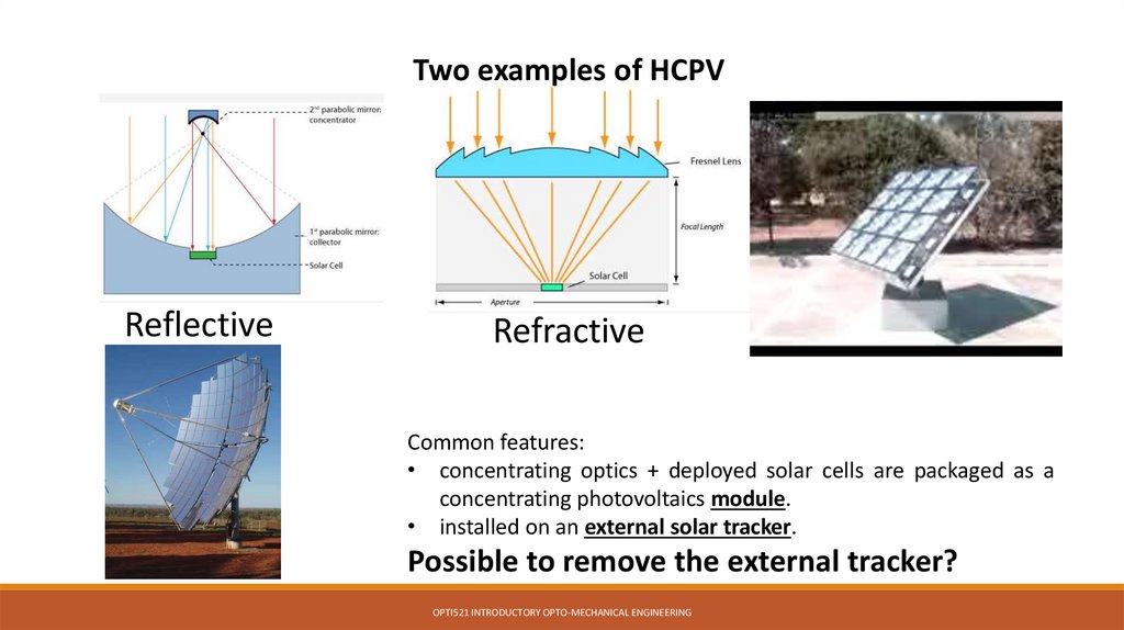
Two examples of HCPVReflective
Refractive
Common features:
• concentrating optics + deployed solar cells are packaged as a
concentrating photovoltaics module.
• installed on an external solar tracker.
Possible to remove the external tracker?
OPTI521 INTRODUCTORY OPTO-MECHANICAL ENGINEERING
6.
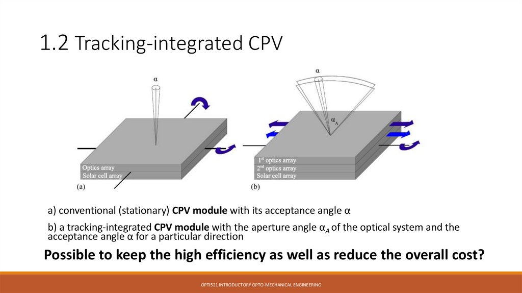
1.2 Tracking-integrated CPVa) conventional (stationary) CPV module with its acceptance angle α
b) a tracking-integrated CPV module with the aperture angle αA of the optical system and the
acceptance angle α for a particular direction
Possible to keep the high efficiency as well as reduce the overall cost?
OPTI521 INTRODUCTORY OPTO-MECHANICAL ENGINEERING
7.
2. Analysis about the Tracking-integrated CPVOne laterally moving optics array and a solar cell array
Two laterally moving optics arrays and a solar cell array
(To reduce the complexity of the integrated tracking as well as the thickness of the overall CPV module
the optics are restricted to lateral movement only)
OPTI521 INTRODUCTORY OPTO-MECHANICAL ENGINEERING
8. 2. Analysis about the Tracking-integrated CPV
2.1 One laterally moving optics array and a solar cellarray
Simultaneous Multiple Surface design method in two
dimensions (SMS2D) is used to design the optics.
SMS surfaces are piecewise curves made of several
portions of Cartesian ovals that map initial ray sets to
final ray sets.
OPTI521 INTRODUCTORY OPTO-MECHANICAL ENGINEERING
9. 2.1 One laterally moving optics array and a solar cell array
Example of a calculatedmeniscus lens for two
parallel ray sets and design
angles θ=±10◦.
(SMS2D)
Within the aperture of the lens, the module obtains a 100× point concentration. But it is not sufficient
to make use of high-efficiency solar cells. How?
OPTI521 INTRODUCTORY OPTO-MECHANICAL ENGINEERING
10.
2.2 Two laterally moving optics arrays and a solarcell array
To properly evaluate the benefit from an additional moving
lens array, the number of two curved optical surfaces should
remain constant.
Extended SMS2D algorithm used to design laterally moving
optics.
OPTI521 INTRODUCTORY OPTO-MECHANICAL ENGINEERING
11. 2.2 Two laterally moving optics arrays and a solar cell array
Offset x2 nd Optical axis
1 st Optical axis
(SMS2D)
2
Working distance W
nd
lens position p
Schematic drawing of a basic optical system
consisting of two laterally moving lenses
and a receiver plane. (Extended SMS2D)
The final results are approximately 20× line concentration and 500×
point concentration over the entire angular range.
Is this the best way?
OPTI521 INTRODUCTORY OPTO-MECHANICAL ENGINEERING
12.
3. Mounting issue and other existing trackingmodule
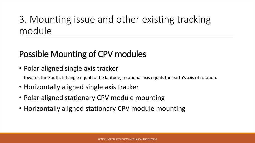
Possible Mounting of CPV modules
• Polar aligned single axis tracker
Towards the South, tilt angle equal to the latitude, rotational axis equals the earth’s axis of rotation.
• Horizontally aligned single axis tracker
• Polar aligned stationary CPV module mounting
• Horizontally aligned stationary CPV module mounting
OPTI521 INTRODUCTORY OPTO-MECHANICAL ENGINEERING
13.
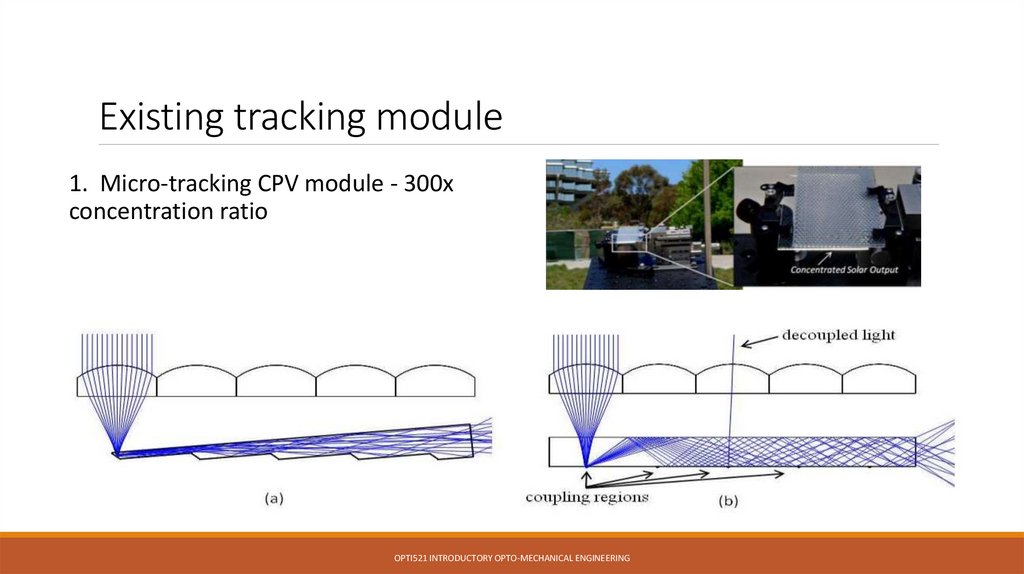
Existing tracking module1. Micro-tracking CPV module - 300x
concentration ratio
OPTI521 INTRODUCTORY OPTO-MECHANICAL ENGINEERING
14. Possible Mounting of CPV modules
Existing tracking module2. Spherical gradient-index lens
1000× concentration ratio
OPTI521 INTRODUCTORY OPTO-MECHANICAL ENGINEERING
15. Existing tracking module
4. Conclusion1. General concept of tracking-integrated CPV and its potential of a lower overall
cost.
2. Detailed benefit-cost analysis will be necessary.
OPTI521 INTRODUCTORY OPTO-MECHANICAL ENGINEERING
16. 2. Spherical gradient-index lens 1000× concentration ratio
THANK YOU!OPTI521 INTRODUCTORY OPTO-MECHANICAL ENGINEERING