


 Интернет
Похожие презентации:


“VRFs” and “Multiprotocol BGP”
1. MPLS VPNs
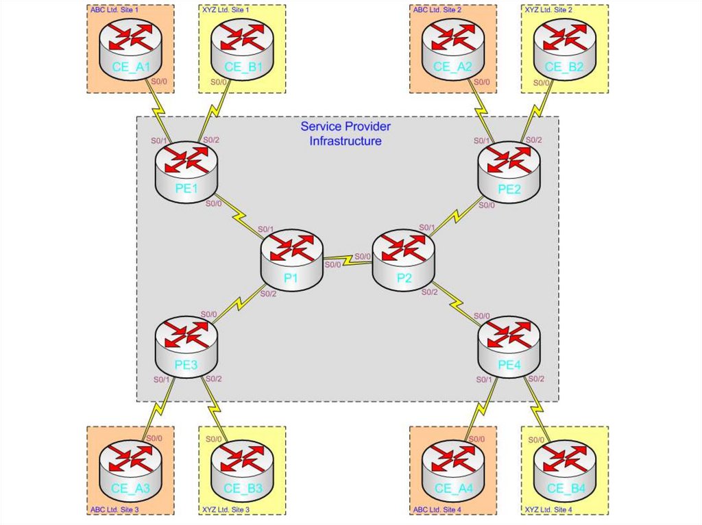
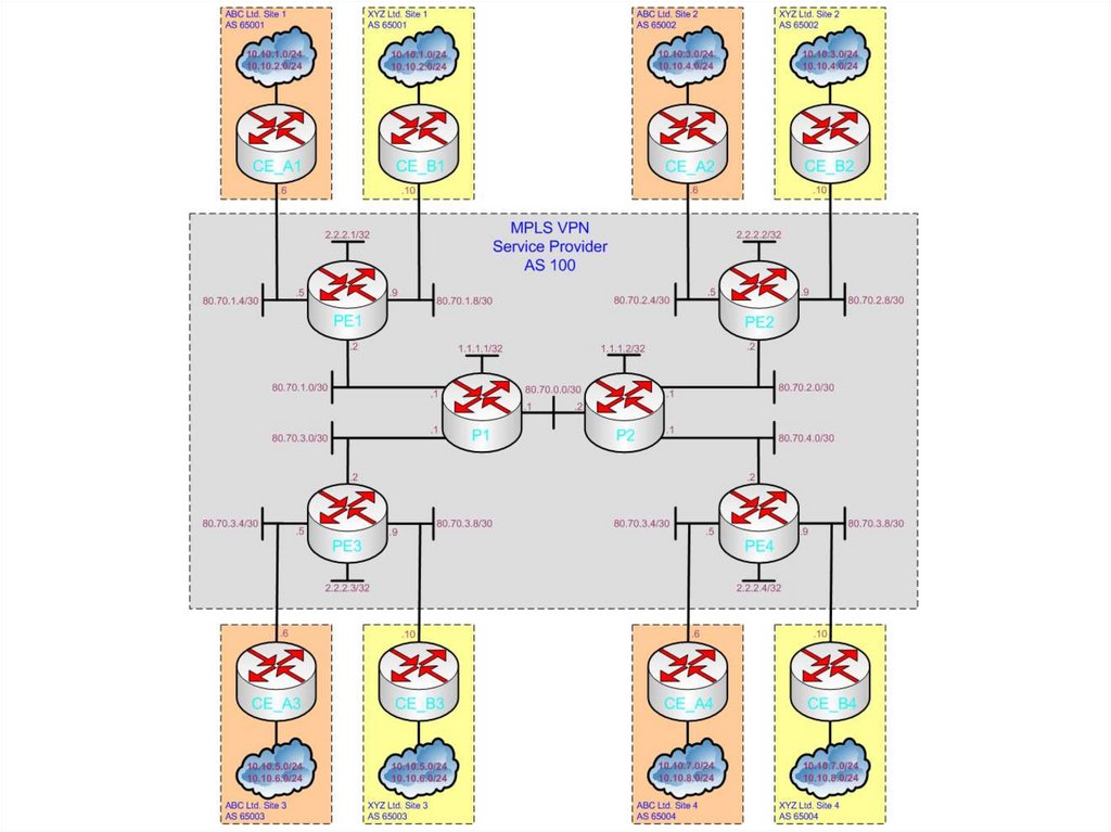
by Richard Bannister2. The Topology
• The next two slides display both thephysical and logical topology of our simple
example network
– Please study the diagrams carefully before
moving on
3.
4.
5. Laying The Foundations
• Terms that are often heard in close proximity to “MPLS VPN” are“VRFs” and “Multiprotocol BGP”. However, before we begin to look
at protocols/features such as these we need to get basic MPLS
Unicast IP Forwarding functioning correctly:
– Step 1 - Enable an IGP on each router within the cloud and verify
routing tables are populated correctly
• BGP (& OSPF) RID reachability is key here
– Step 2 - Enable MPLS on all ‘provider router to provider router’
interfaces
• An available label will then be chosen by each router and advertised on all
interfaces configured for MPLS using TDP (old default) or LDP (new default
& what we’ll use) for each prefix learned via the IGP
– OSPF will be configured as the IGP in this example
– Remember. LDP ‘floods’ in all directions so routers will consult the routing table to
make a decision on which label path to use for a given prefix (important when
loops exist)
6. Inside The Cloud
7. Overlaying MPLS VPNs
• Now that the ‘cloud’ has basic MPLS IP UnicastForwarding enabled we can create Virtual
Routing and Forwarding (VRF) tables and make
use of Multiprotocol BGP (MP-BGP/MBGP) to
advertise prefixes held within the VRFs
– In addition to the standard MPLS label used for
Unicast IP Forwarding (now the “outer label” and used
to reach a BGP next-hop), an “inner label” will now be
added to packets to inform other PE routers of the
correct egress VRF tables to place packets in upon
receiving them (ready for standard forwarding)
• This is how a ‘VPN’ is created – by separating routing
information per-customer at the edge of the cloud and
ignoring IP headers for forwarding within the cloud
8. Customer to Provider
• As MPLS is a layer 3 technology a method ofcommunicating routing information between the
customer (with possible overlapping prefixes
with other customers) and the provider (VRF
tables used to separate customers) is required
– Methods of CE to PE route advertisement include:
Static routing
RIPv2
EIGRP
OSPF
BGP