


 Электроника
Похожие презентации:


")


For classroom G5951 DC fundamentals
1.
PRESENTATION FOR CLASSROOM G5951DC fundamentals
3ADW000547R0201 DC FUNDAMENTALS EN B
2.
ContentDC motor:
Introduction
Design
Physical way a DC motor works and equations
Characteristics of a DC drives
DC drive:
General Layout
Armature converter and commutation chokes
Converter current, calculations and discontinuous current
Operating mode and control structure
August 25, 2020
Slide 2
3.
DC motorIntroduction
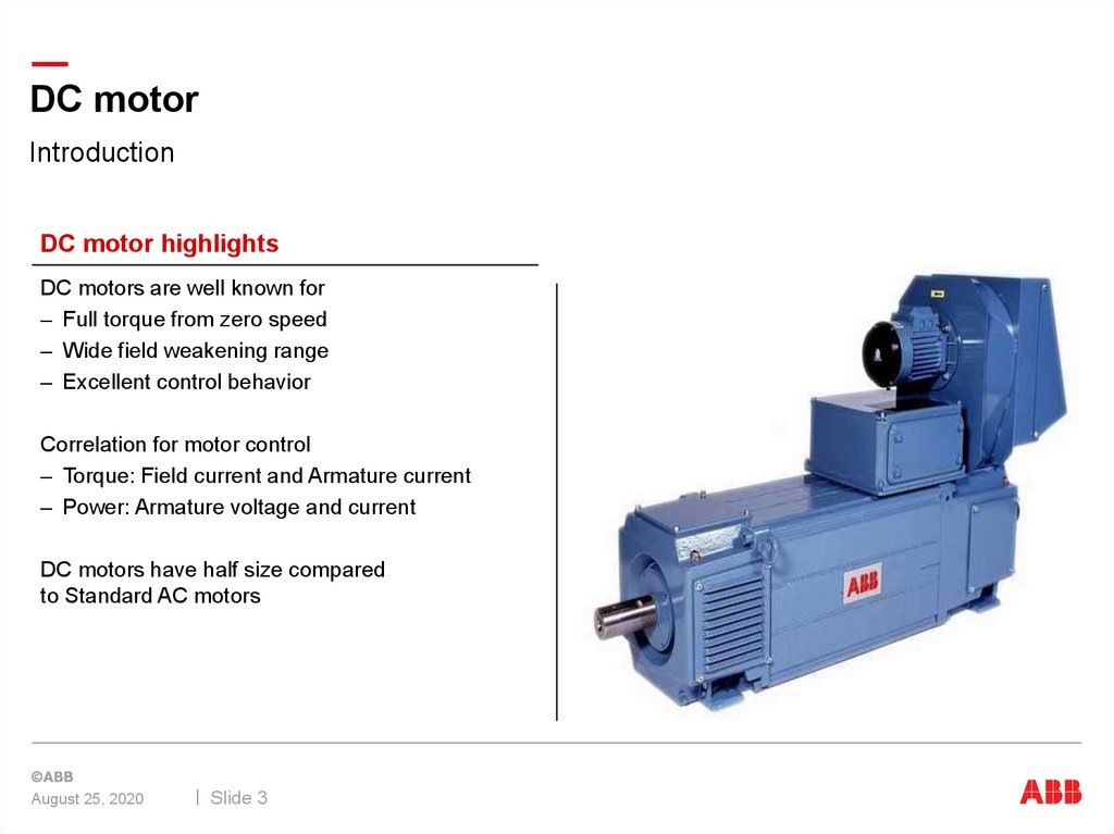
DC motor highlights
DC motors are well known for
– Full torque from zero speed
– Wide field weakening range
– Excellent control behavior
Correlation for motor control
– Torque: Field current and Armature current
– Power: Armature voltage and current
DC motors have half size compared
to Standard AC motors
August 25, 2020
Slide 3
4.
DC motorIntroduction
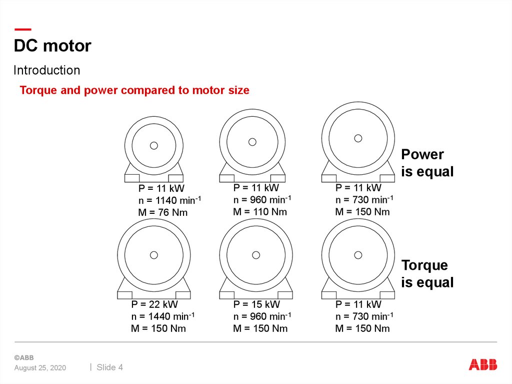
Torque and power compared to motor size
Power
is equal
P = 11 kW
n = 1140 min-1
M = 76 Nm
P = 11 kW
n = 960 min-1
M = 110 Nm
P = 11 kW
n = 730 min-1
M = 150 Nm
Torque
is equal
P = 22 kW
n = 1440 min-1
M = 150 Nm
August 25, 2020
Slide 4
P = 15 kW
n = 960 min-1
M = 150 Nm
P = 11 kW
n = 730 min-1
M = 150 Nm
5.
DC motorDesign - Stator of a DC machine
4 poles stator
Stator is the stationary part
Main poles as field winding
Further windings
Interpole
Compensation
eliminate un-wanted effects
August 25, 2020
Slide 5
6.
DC motorPhysical way a DC motor works
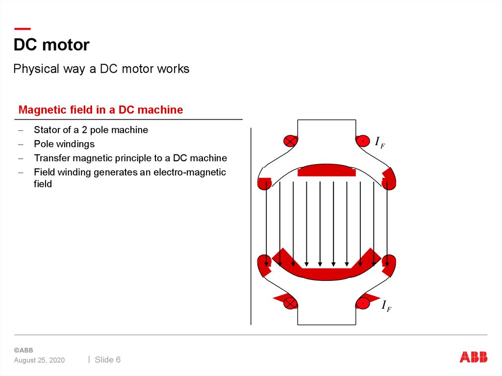
Magnetic field in a DC machine
Stator of a 2 pole machine
Pole windings
Transfer magnetic principle to a DC machine
Field winding generates an electro-magnetic
field
IF
IF
August 25, 2020
Slide 6
7.
DC motorPhysical way a DC motor works
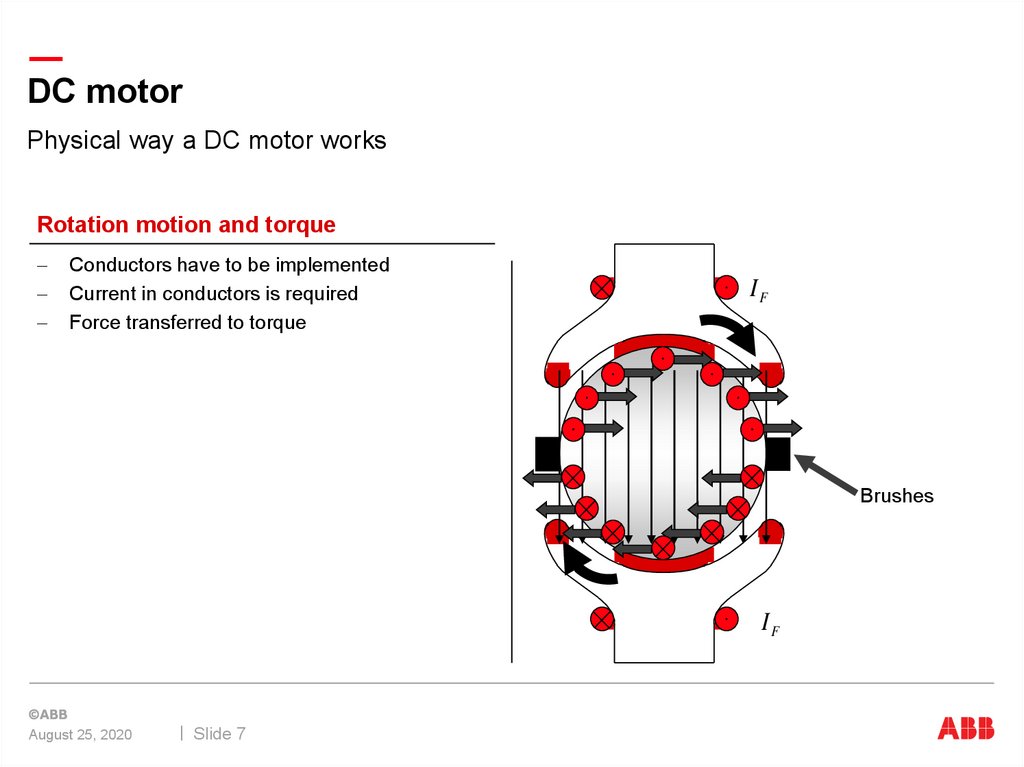
Rotation motion and torque
Conductors have to be implemented
Current in conductors is required
Force transferred to torque
IF
Brushes
IF
August 25, 2020
Slide 7
8.
DC motorPhysical way a DC motor works
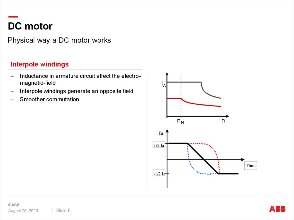
Interpole windings
Inductance in armature circuit affect the electromagnetic-field
Interpole windings generate an opposite field
Smoother commutation
IA
nN
n
Ia
1/2 Ia
Time
-1/2 Ia
August 25, 2020
Slide 8
9.
DC motorPhysical way a DC motor works
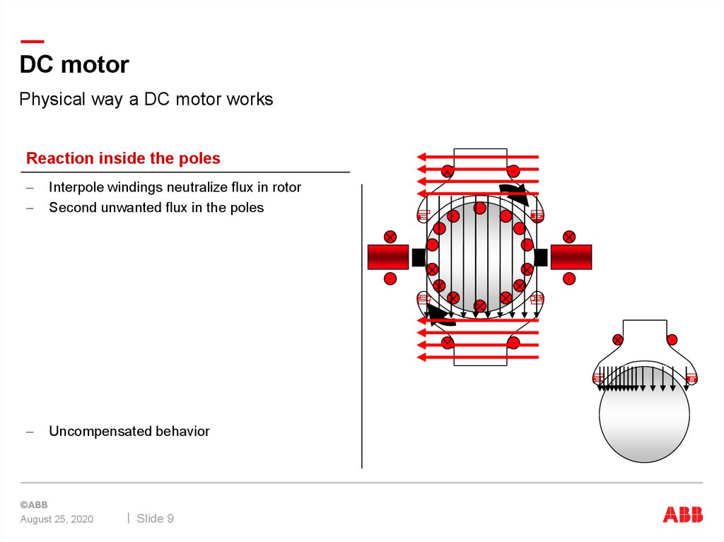
Reaction inside the poles
Interpole windings neutralize flux in rotor
Second unwanted flux in the poles
Uncompensated behavior
August 25, 2020
Slide 9
10.
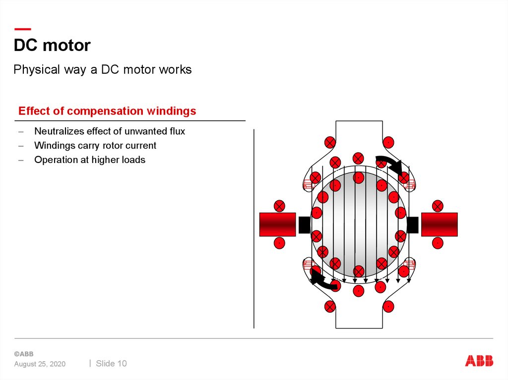
DC motorPhysical way a DC motor works
Effect of compensation windings
Neutralizes effect of unwanted flux
Windings carry rotor current
Operation at higher loads
August 25, 2020
Slide 10
11.
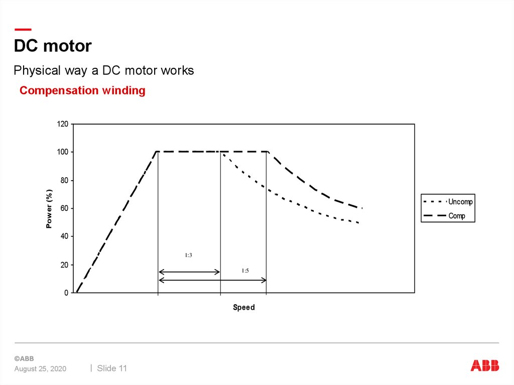
DC motorPhysical way a DC motor works
Compensation winding
120
100
Power (%)
80
Uncomp
60
Comp
40
1:3
20
1:5
0
Speed
August 25, 2020
Slide 11
12.
DC motorPhysical way a DC motor works
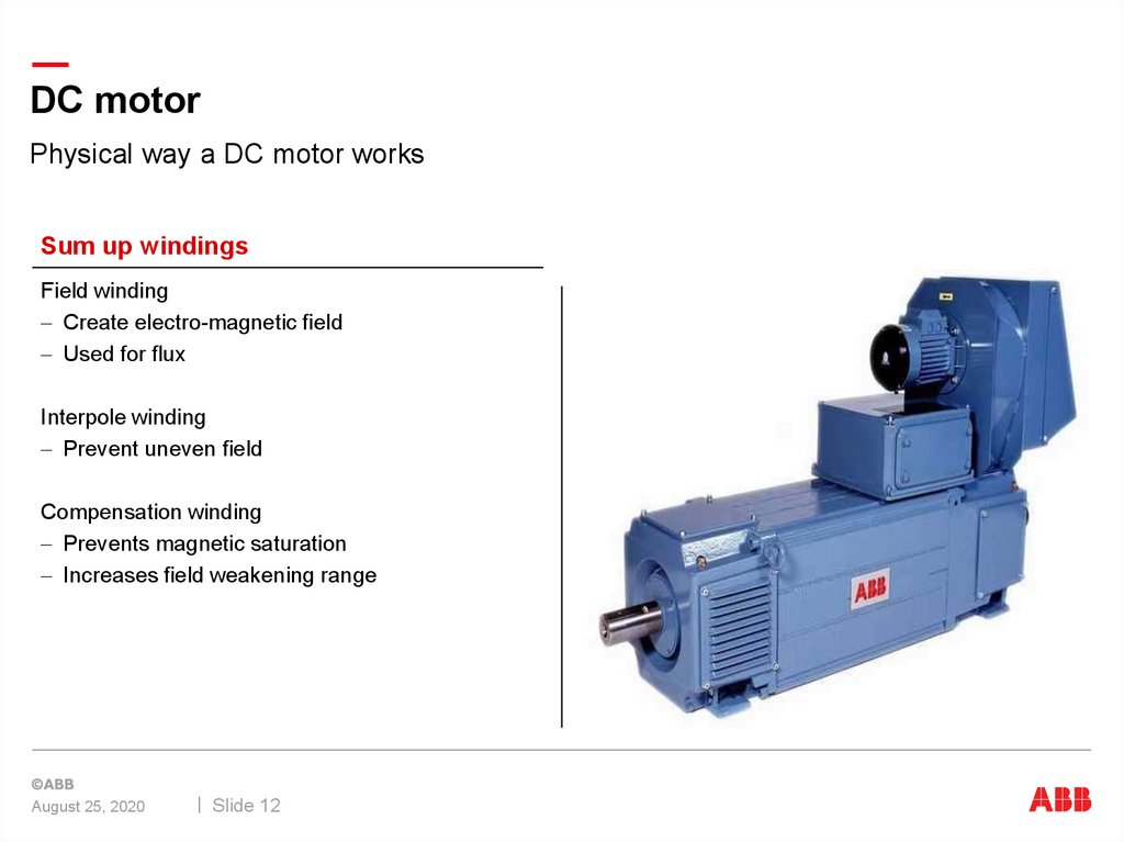
Sum up windings
Field winding
Create electro-magnetic field
Used for flux
Interpole winding
Prevent uneven field
Compensation winding
Prevents magnetic saturation
Increases field weakening range
August 25, 2020
Slide 12
13.
DC motorDesign
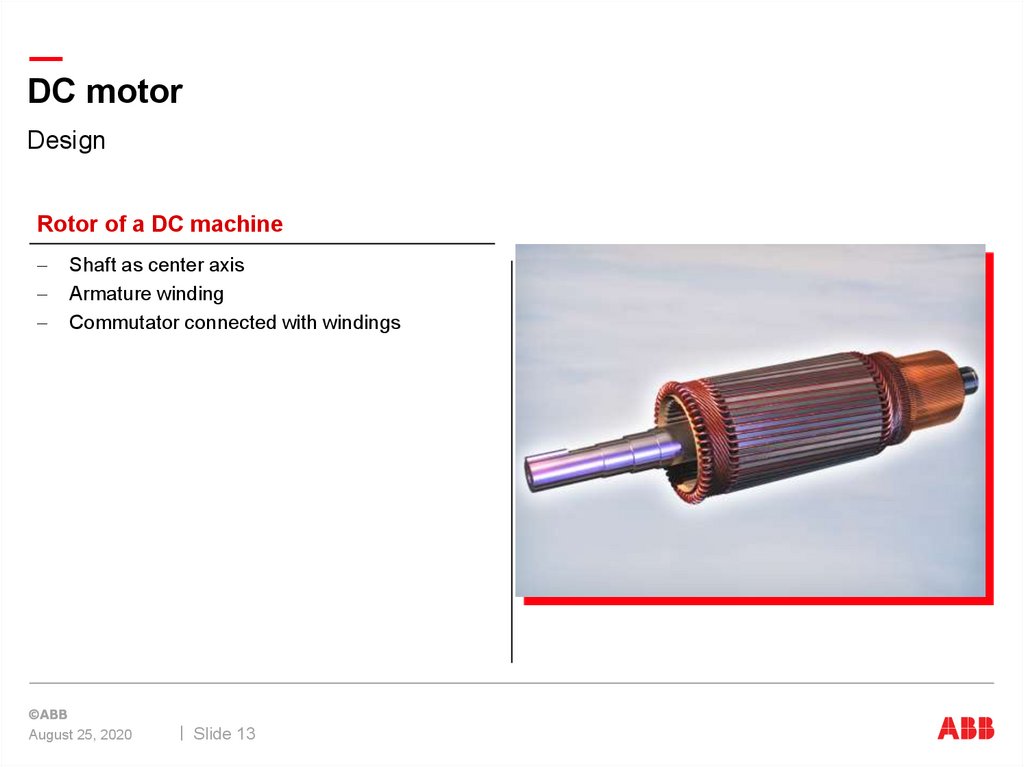
Rotor of a DC machine
Shaft as center axis
Armature winding
Commutator connected with windings
August 25, 2020
Slide 13
14.
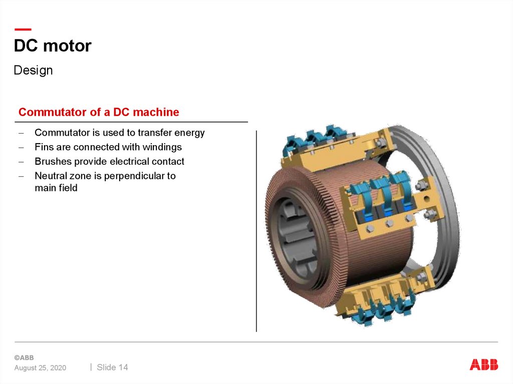
DC motorDesign
Commutator of a DC machine
Commutator is used to transfer energy
Fins are connected with windings
Brushes provide electrical contact
Neutral zone is perpendicular to
main field
August 25, 2020
Slide 14
15.
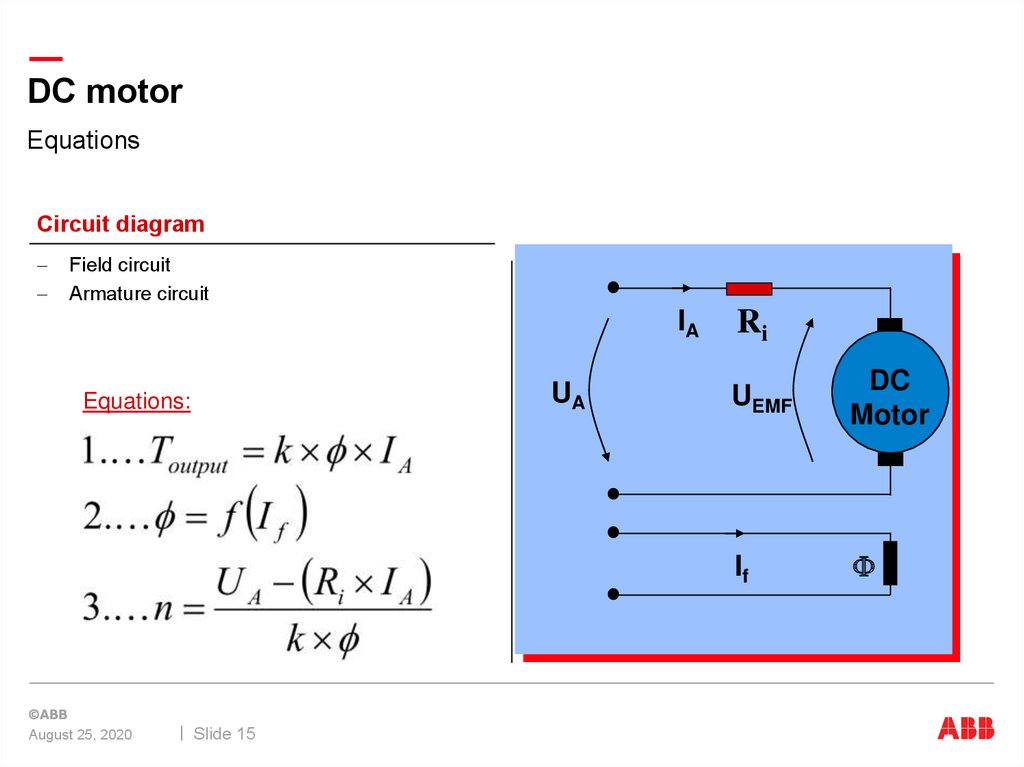
DC motorEquations
Circuit diagram
Field circuit
Armature circuit
IA
UA
Equations:
August 25, 2020
Slide 15
Ri
UEMF
DC
Motor
If
F
16.
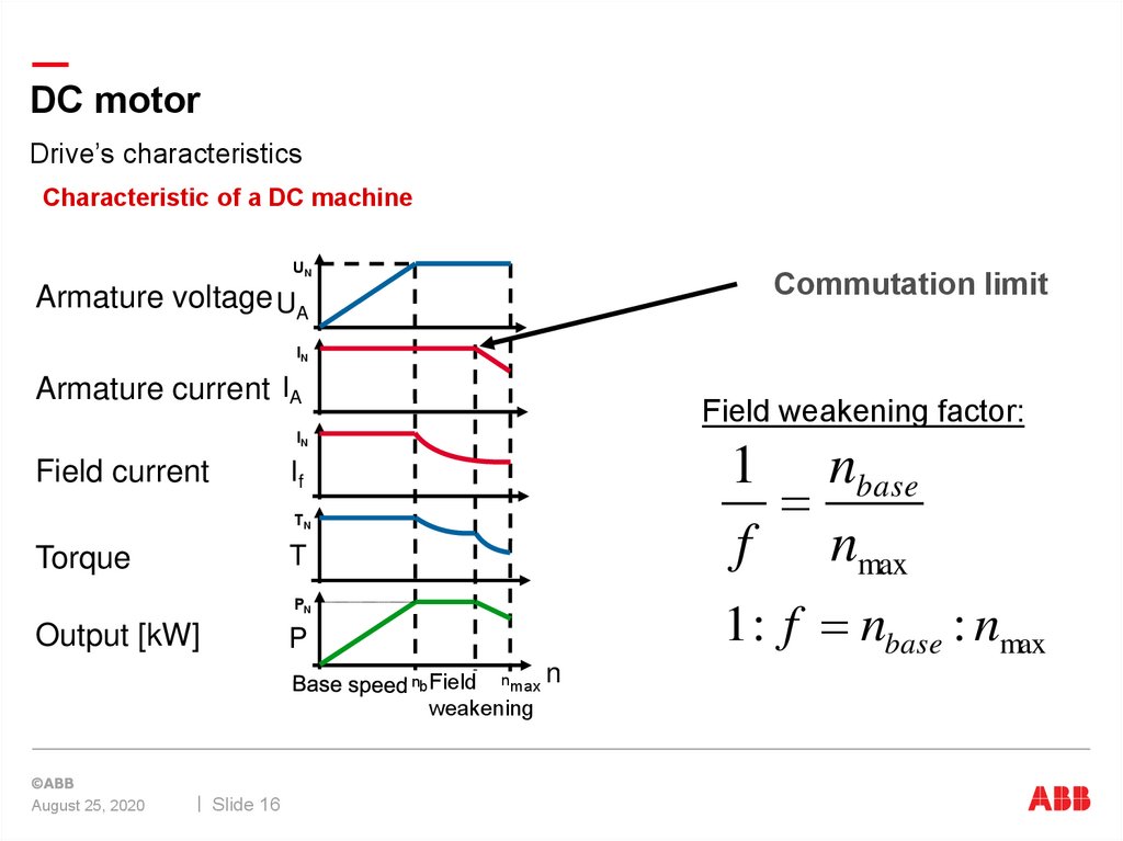
DC motorDrive’s characteristics
Characteristic of a DC machine
UN
Commutation limit
Armature voltage UA
IN
Armature current IA
Field weakening factor:
IN
Field current
1 nbase
f nmax
If
TN
T
Torque
1 : f nbase : nmax
PN
Output [kW]
P
nb Field
n max
weakening
August 25, 2020
Slide 16
n
17.
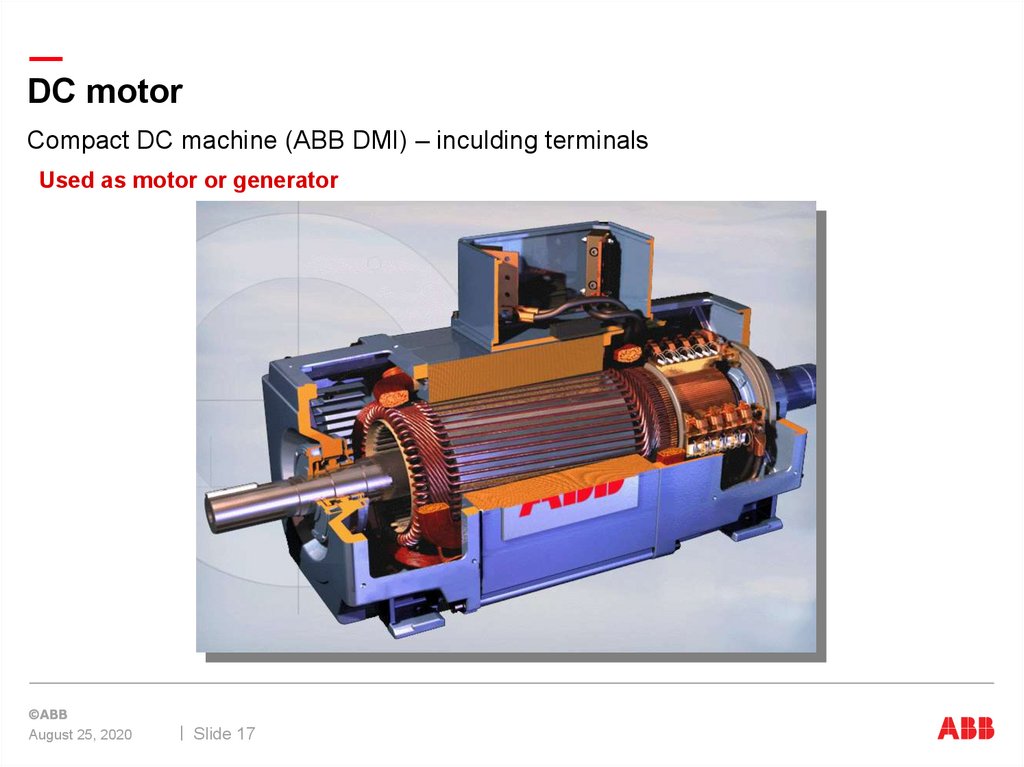
DC motorCompact DC machine (ABB DMI) – inculding terminals
Used as motor or generator
August 25, 2020
Slide 17
18.
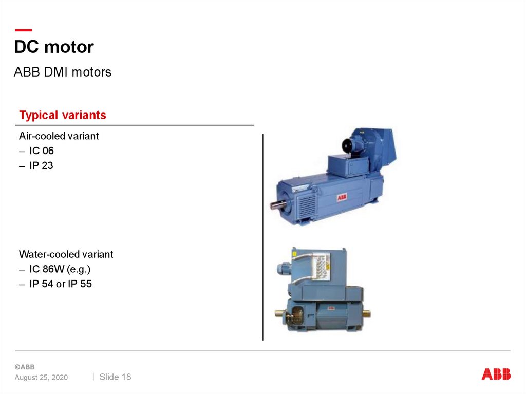
DC motorABB DMI motors
Typical variants
Air-cooled variant
– IC 06
– IP 23
Water-cooled variant
– IC 86W (e.g.)
– IP 54 or IP 55
August 25, 2020
Slide 18
19.
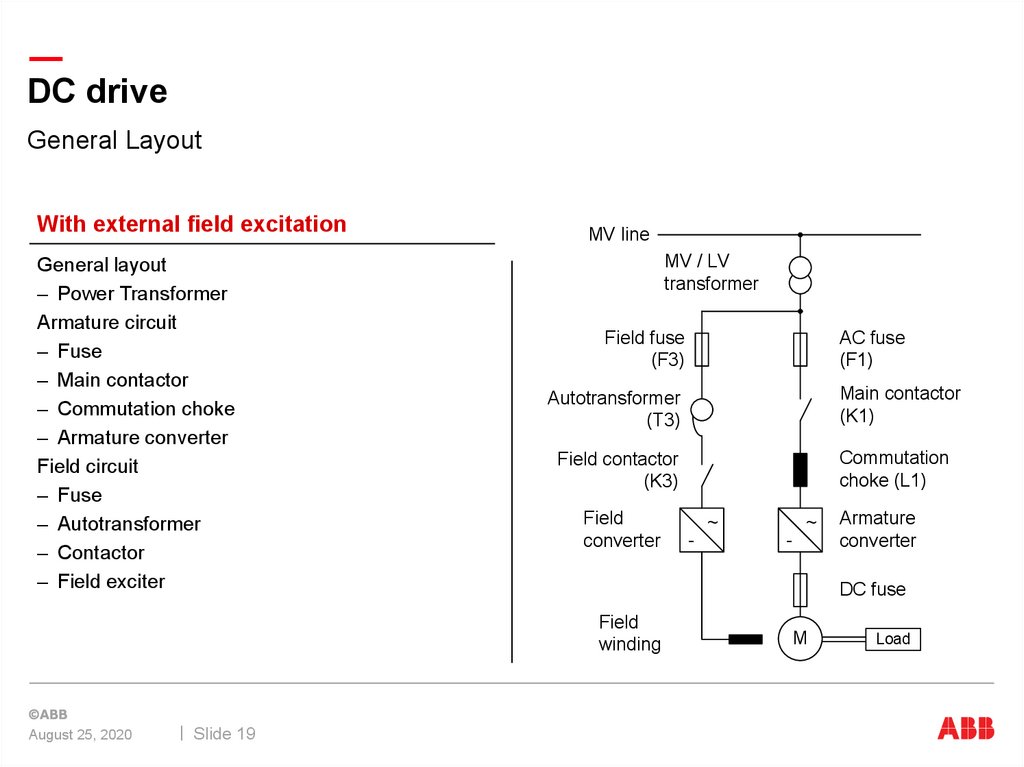
DC driveGeneral Layout
With external field excitation
General layout
– Power Transformer
Armature circuit
– Fuse
– Main contactor
– Commutation choke
– Armature converter
Field circuit
– Fuse
– Autotransformer
– Contactor
– Field exciter
MV line
MV / LV
transformer
Field fuse
(F3)
Slide 19
Main contactor
(K1)
Autotransformer
(T3)
Commutation
choke (L1)
Field contactor
(K3)
Field
converter
~
~
-
-
Armature
converter
DC fuse
Field
winding
August 25, 2020
AC fuse
(F1)
M
Load
20.
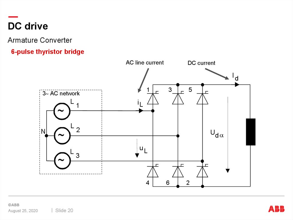
DC driveArmature Converter
6-pulse thyristor bridge
AC line current
DC current
Id
1
3 AC network
L
~
N
L
~
L
~
1
Slide 20
5
iL
2
3
Ud a
uL
4
August 25, 2020
3
6
2
21.
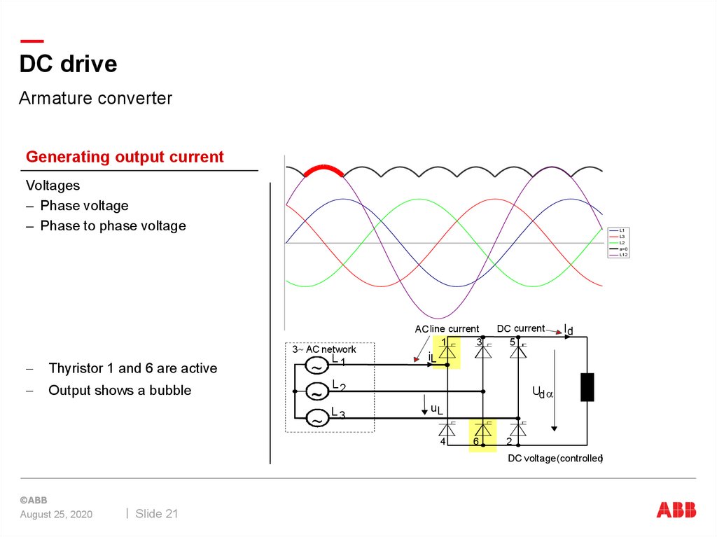
DC driveArmature converter
Generating output current
Voltages
– Phase voltage
– Phase to phase voltage
L1
L3
L1
L2
L3
a=0
L2
a=0
L12
3 AC network
Thyristor 1 and 6 are active
Output shows a bubble
~
~
~
L1
ACline current
1
3
DC current
5
iL
L2
L3
Id
Ud a
uL
4
6
2
DC voltage(controlled)
August 25, 2020
Slide 21
22.
DC driveArmature converter
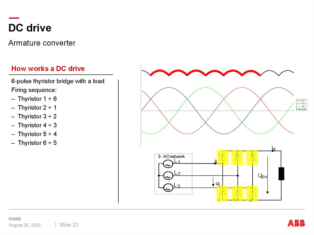
How works a DC drive
6-pulse thyristor bridge with a load
Firing sequence:
– Thyristor 1 + 6
– Thyristor 2 + 1
– Thyristor 3 + 2
– Thyristor 4 + 3
– Thyristor 5 + 4
– Thyristor 6 + 5
L1
L3
L2
a=0
Id
3 ACnetwork
~
~
~
L1
1
iL
Slide 22
5
L2
L3
Ud a
uL
4
August 25, 2020
3
6
2
23.
DC driveArmature converter in “driving mode”
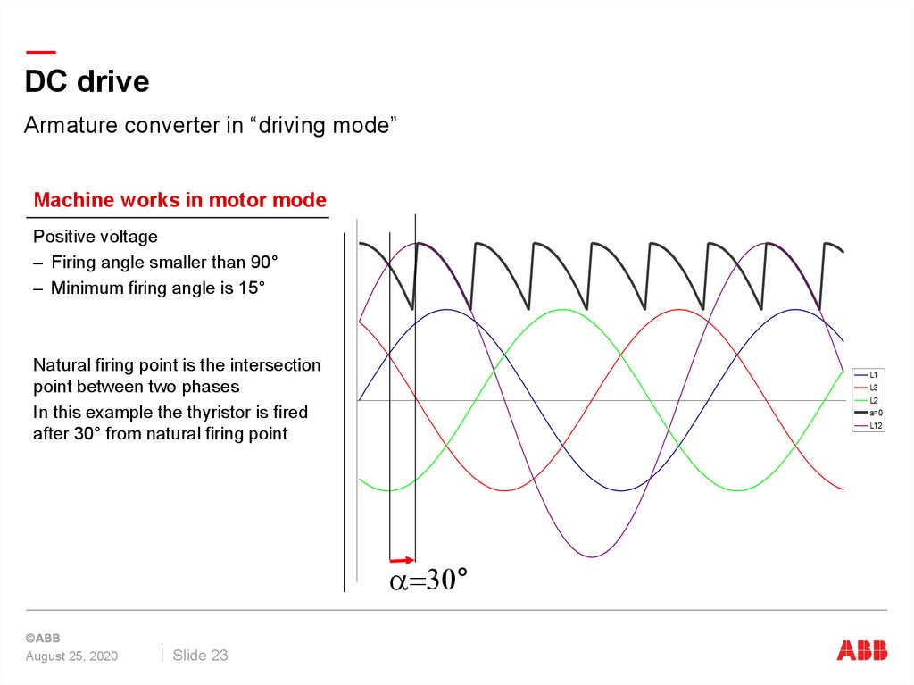
Machine works in motor mode
Positive voltage
– Firing angle smaller than 90°
– Minimum firing angle is 15°
Natural firing point is the intersection
point between two phases
In this example the thyristor is fired
after 30° from natural firing point
L1
L3
L2
a=0
L12
a 30°
August 25, 2020
Slide 23
24.
DC driveArmature converter in “braking mode”
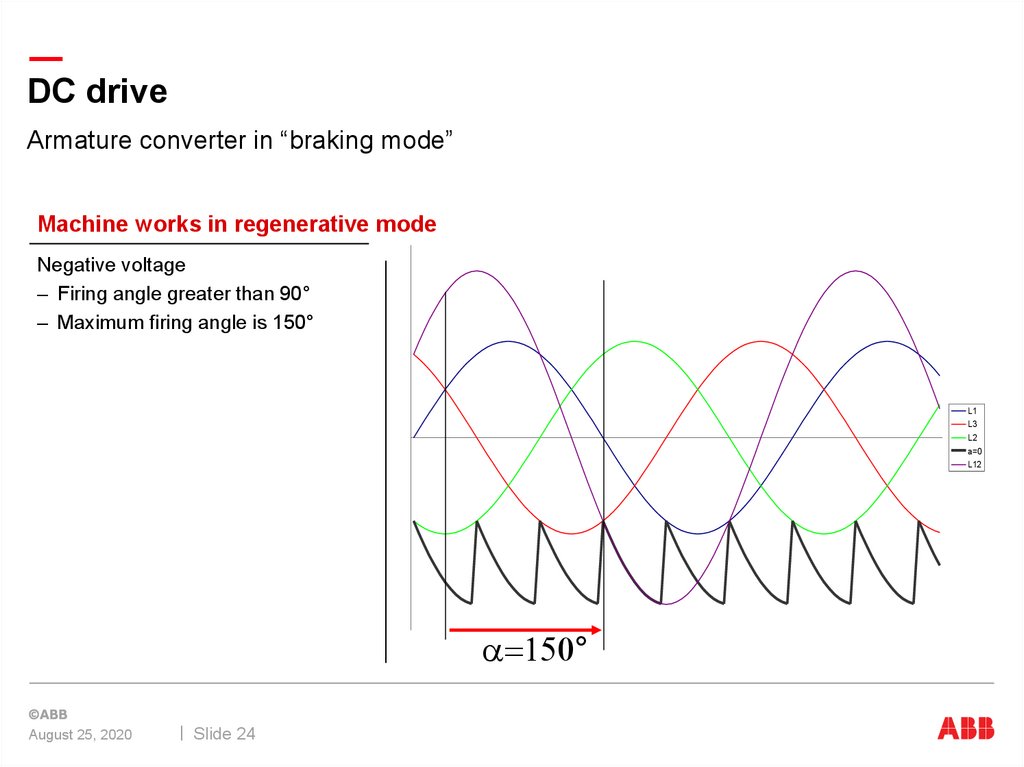
Machine works in regenerative mode
Negative voltage
– Firing angle greater than 90°
– Maximum firing angle is 150°
L1
L3
L2
a=0
L12
a 150°
August 25, 2020
Slide 24
25.
DC driveArmature converter in Shoot-through
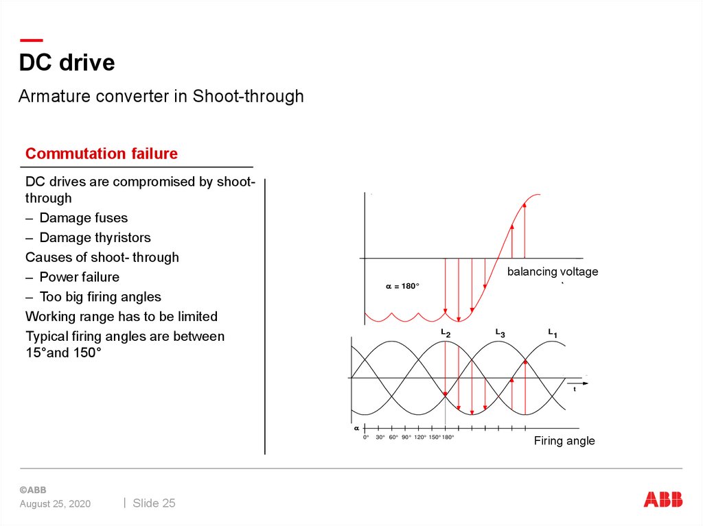
Commutation failure
DC drives are compromised by shootthrough
– Damage fuses
– Damage thyristors
Causes of shoot- through
– Power failure
– Too big firing angles
Working range has to be limited
Typical firing angles are between
15°and 150°
GDCZ142
WECHSELRICHTERKIPPEN
Ausgangsgleichspannung
balancing voltage
t
a = 180°
L2
L3
L1
Netzspannung
t
a
0°
Zündwinkel
30° 60° 90° 120° 150° 180°
Firing angle
1
2
3
4
5
6
Zündimpulsreihenfolge an den Thyristoren
August 25, 2020
Slide 25
3
1
5
4
6
Stromführungsdauer der Thyristoren
26.
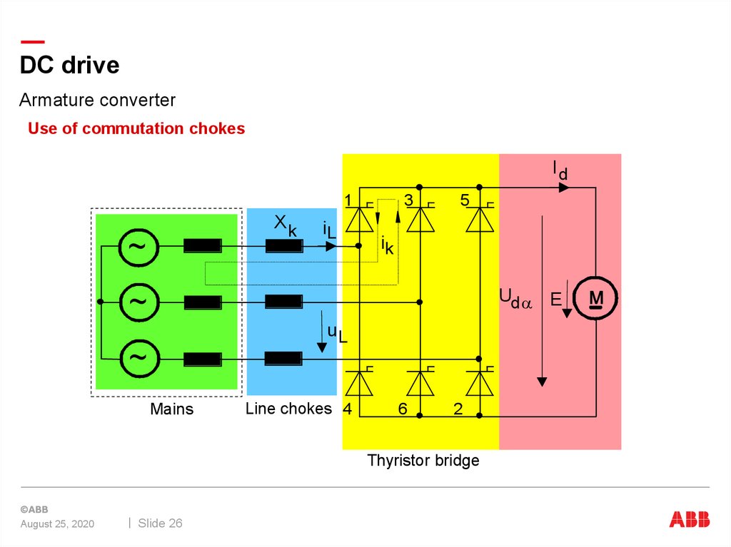
DC driveArmature converter
Use of commutation chokes
Id
1
Xk
~
iL
3
5
ik
Ud a E
~
uL
~
Mains
Line chokes 4
6
2
Thyristor bridge
August 25, 2020
Slide 26
27.
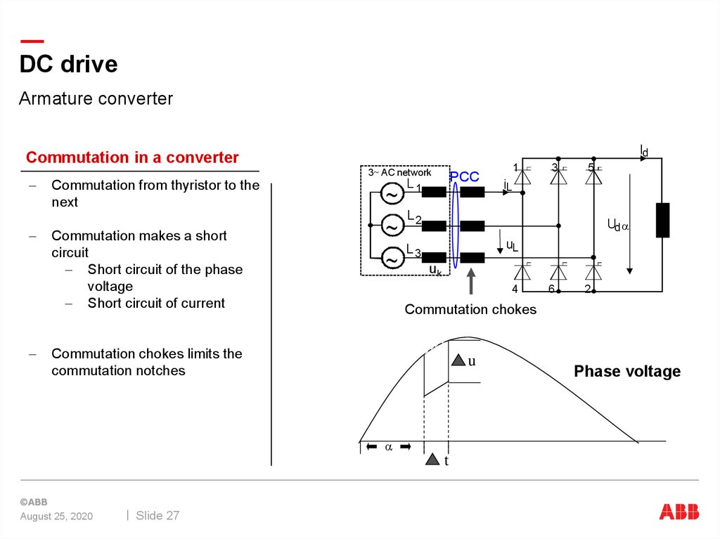
DC driveArmature converter
Commutation in a converter
Commutation from thyristor to the
next
Commutation makes a short
circuit
Short circuit of the phase
voltage
Short circuit of current
Id
3 AC network
~
~
~
PCC
L1
5
iL
Ud a
uL
L3
uk
4
6
2
Commutation chokes
u
a
t
Slide 27
3
L2
Commutation chokes limits the
commutation notches
August 25, 2020
1
Phase voltage
28.
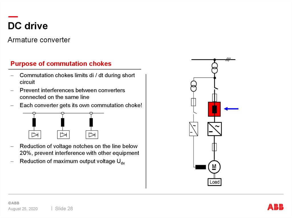
DC driveArmature converter
Purpose of commutation chokes
Commutation chokes limits di / dt during short
circuit
Prevent interferences between converters
connected on the same line
Each converter gets its own commutation choke!
~
~
Reduction of voltage notches on the line below
20%, prevent interference with other equipment
Reduction of maximum output voltage Udx
Load
August 25, 2020
Slide 28
29.
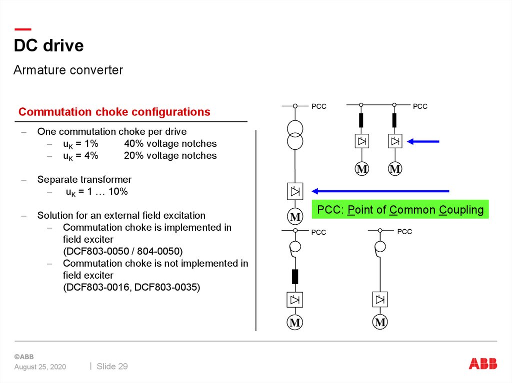
DC driveArmature converter
PCC
Commutation choke configurations
PCC
One commutation choke per drive
uK = 1%
40% voltage notches
uK = 4%
20% voltage notches
M
Separate transformer
uK = 1 … 10%
Solution for an external field excitation
Commutation choke is implemented in
field exciter
(DCF803-0050 / 804-0050)
Commutation choke is not implemented in
field exciter
(DCF803-0016, DCF803-0035)
M
Slide 29
PCC: Point of Common Coupling
PCC
PCC
M
August 25, 2020
M
M
30.
DC driveArmature converter
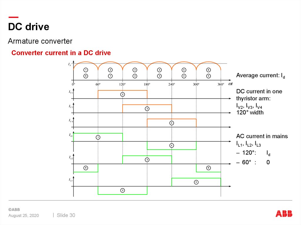
Converter current in a DC drive
Id
1
2
3
4
5
6
6
1
2
3
4
5
60
0
IV 2
120
180
240
360
300
3
IV 4
4
I L1
AC current in mains
IL1, IL2, IL3
1
4
I L2
3
6
6
I L3
5
2
August 25, 2020
Slide 30
t
DC current in one
thyristor arm:
IV2, IV3, IV4
120° width
2
IV 3
Average current: Id
– 120°:
Id
– 60° :
0
31.
DC driveCalculations
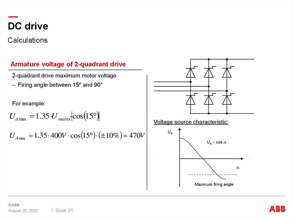
Armature voltage of 2-quadrant drive
2-quadrant drive maximum motor voltage
– Firing angle between 15° and 90°
For example:
U d max 1.35 U mains cos 15
U A max 1.35 400V cos 15 10% 470V
Voltage source characteristic:
Ud
Ud cos a
a
Maximum firing angle
August 25, 2020
Slide 31
32.
DC driveCalculations
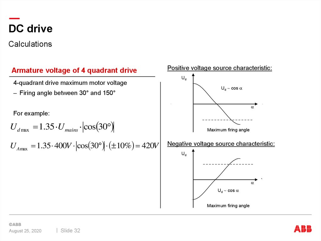
Armature voltage of 4 quadrant drive
4-quadrant drive maximum motor voltage
Positive voltage source characteristic:
Ud
Ud cos a
– Firing angle between 30° and 150°
a
For example:
U d max 1.35 U mains cos 30
U Amax 1.35 400V cos 30 10% 420V
Maximum firing angle
Negative voltage source characteristic:
Ud
a
Ud cos a
Maximum firing angle
August 25, 2020
Slide 32
33.
DC driveCalculations
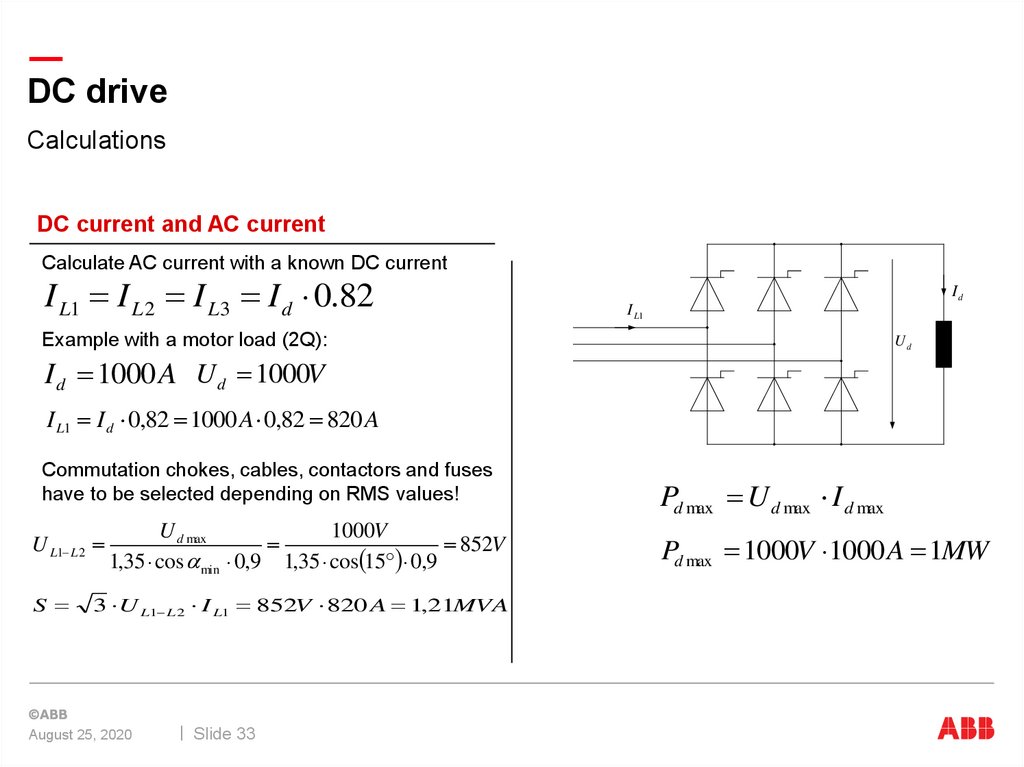
DC current and AC current
Calculate AC current with a known DC current
I L1 I L 2 I L3 I d 0.82
Id
I L1
Example with a motor load (2Q):
Ud
I d 1000 A U d 1000V
I L1 I d 0,82 1000 A 0,82 820 A
Commutation chokes, cables, contactors and fuses
have to be selected depending on RMS values!
U L1 L 2
S
U d max
1000V
852V
1,35 cos a min 0,9 1,35 cos 15 0,9
3 U L1 L 2 I L1 852V 820 A 1,21MVA
August 25, 2020
Slide 33
Pd max U d max I d max
Pd max 1000V 1000 A 1MW
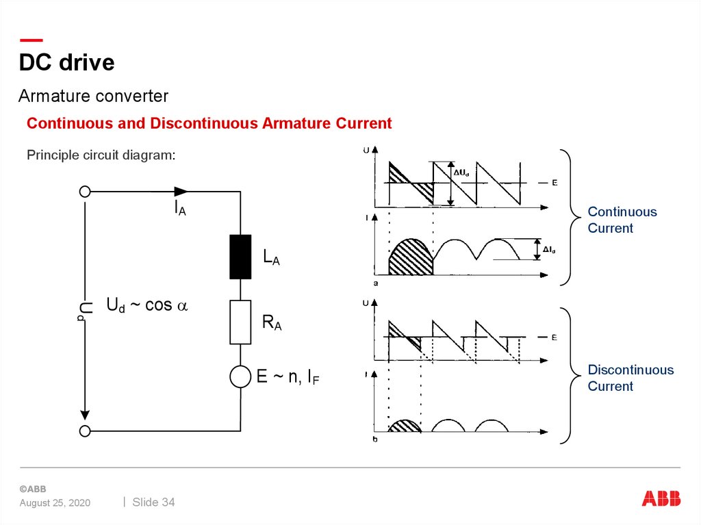
34.
DC driveArmature converter
Continuous and Discontinuous Armature Current
Principle circuit diagram:
IA
Continuous
Current
LA
Ud
Ud ~ cos a
RA
E ~ n, IF
August 25, 2020
Slide 34
Discontinuous
Current
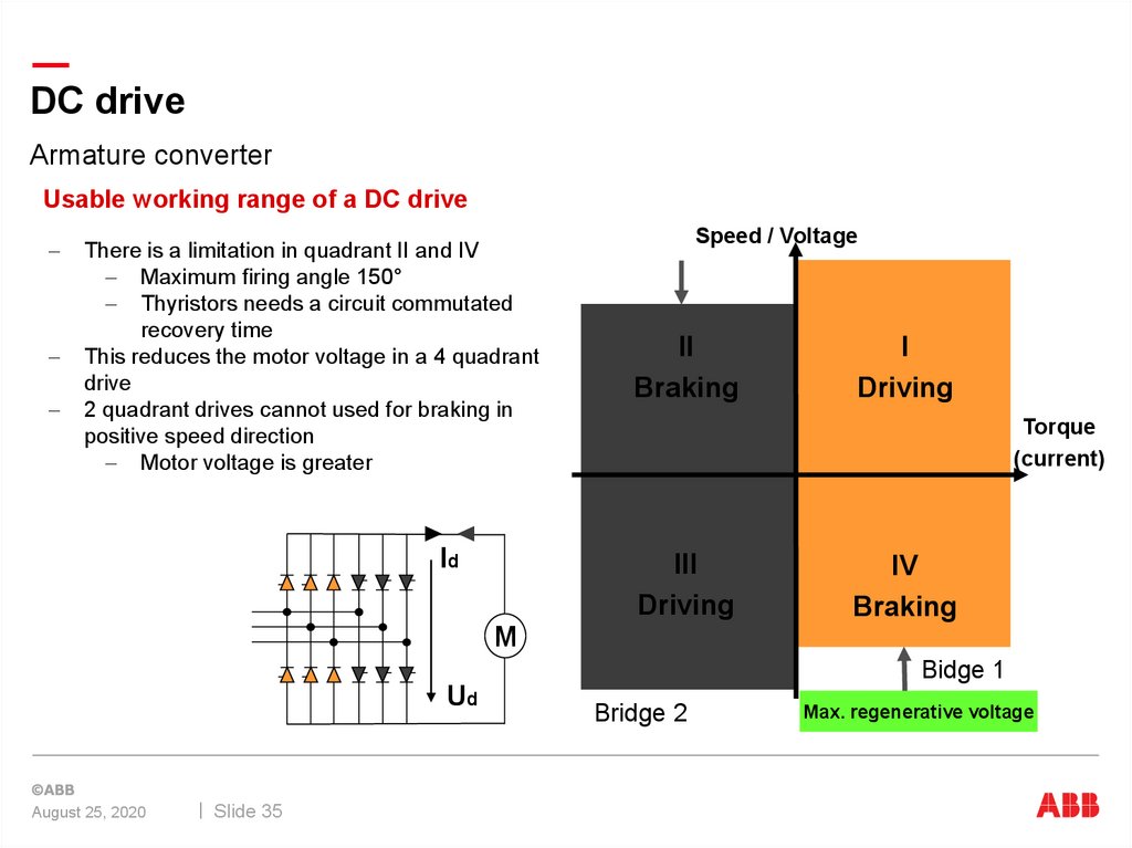
35.
DC driveArmature converter
Usable working range of a DC drive
There is a limitation in quadrant II and IV
Maximum firing angle 150°
Thyristors needs a circuit commutated
recovery time
This reduces the motor voltage in a 4 quadrant
drive
2 quadrant drives cannot used for braking in
positive speed direction
Motor voltage is greater
Id
Speed / Voltage
II
Braking
I
Driving
Torque
(current)
III
Driving
IV
Braking
M
Bidge 1
Ud
August 25, 2020
Slide 35
Bridge 2
Max. regenerative voltage
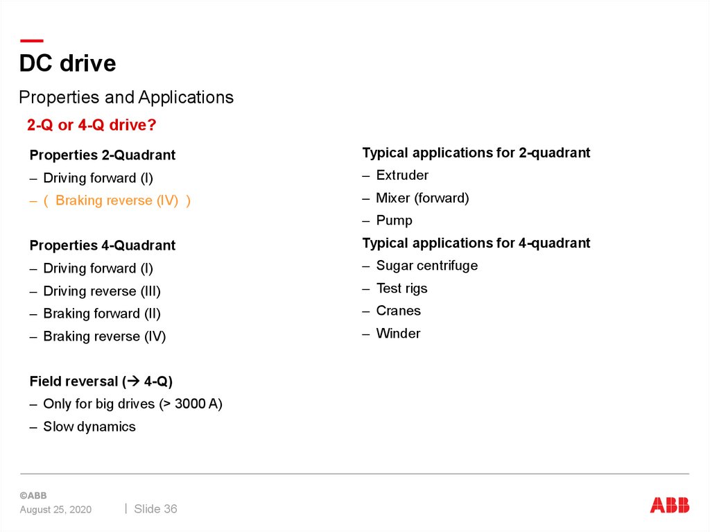
36.
DC driveProperties and Applications
2-Q or 4-Q drive?
Properties 2-Quadrant
Typical applications for 2-quadrant
– Driving forward (I)
– Extruder
– ( Braking reverse (IV) )
– Mixer (forward)
– Pump
Properties 4-Quadrant
Typical applications for 4-quadrant
– Driving forward (I)
– Sugar centrifuge
– Driving reverse (III)
– Test rigs
– Braking forward (II)
– Cranes
– Braking reverse (IV)
– Winder
Field reversal ( 4-Q)
– Only for big drives (> 3000 A)
– Slow dynamics
August 25, 2020
Slide 36
37.
DC driveControl structure
Diagram
August 25, 2020
Slide 37