 Программное обеспечение
Похожие презентации:


")


2D Pipe Junction. Introduction to ANSYS ICEM CFD
1.
Workshop 8.12D Pipe Junction
14. 0 Release
Introduction to ANSYS
ICEM CFD
1
© 2011 ANSYS, Inc.
March 3, 2021
Release 14.0
2.
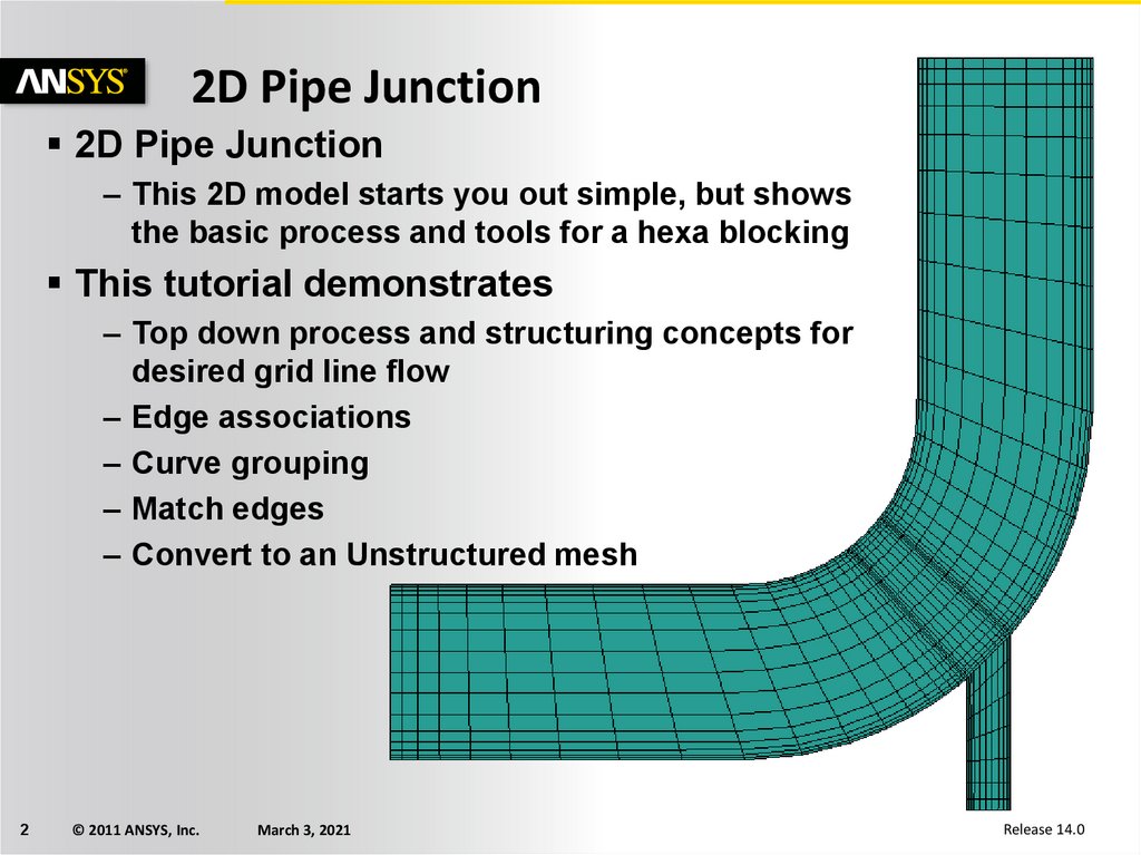
2D Pipe Junction2D Pipe Junction
– This 2D model starts you out simple, but shows
the basic process and tools for a hexa blocking
This tutorial demonstrates
– Top down process and structuring concepts for
desired grid line flow
– Edge associations
– Curve grouping
– Match edges
– Convert to an Unstructured mesh
2
© 2011 ANSYS, Inc.
March 3, 2021
Release 14.0
3.
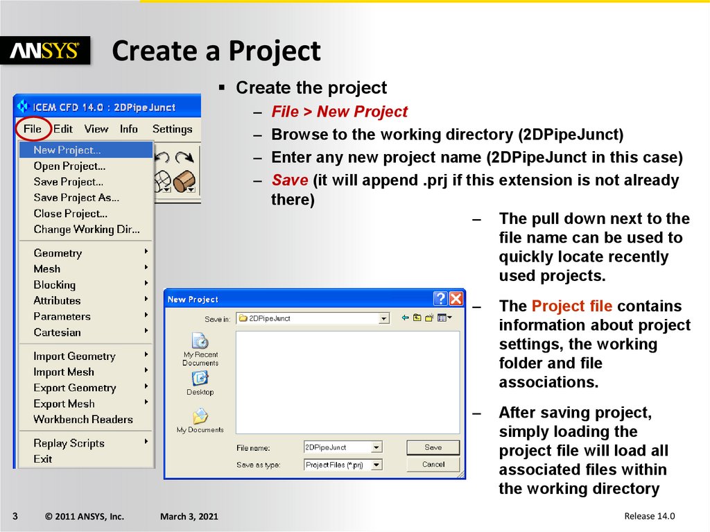
Create a ProjectCreate the project
–
–
–
–
3
© 2011 ANSYS, Inc.
March 3, 2021
File > New Project
Browse to the working directory (2DPipeJunct)
Enter any new project name (2DPipeJunct in this case)
Save (it will append .prj if this extension is not already
there)
– The pull down next to the
file name can be used to
quickly locate recently
used projects.
–
The Project file contains
information about project
settings, the working
folder and file
associations.
–
After saving project,
simply loading the
project file will load all
associated files within
the working directory
Release 14.0
4.
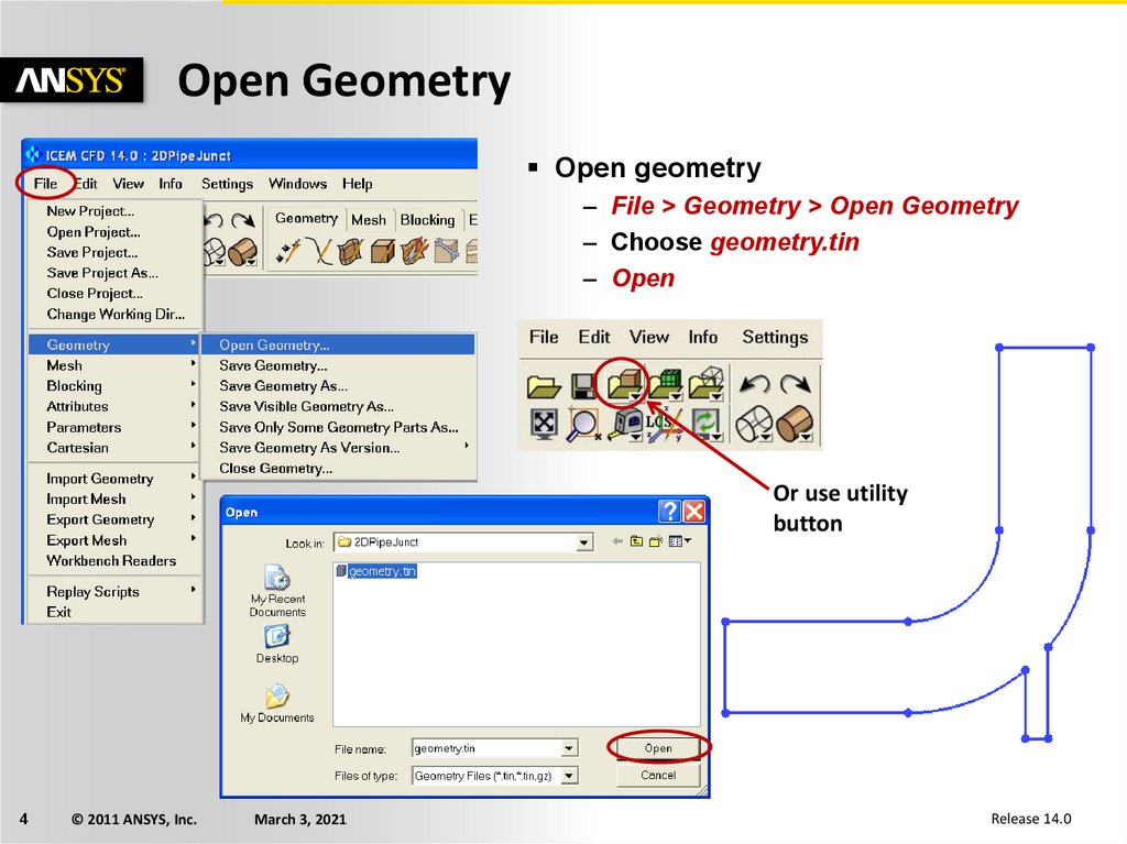
Open GeometryOpen geometry
– File > Geometry > Open Geometry
– Choose geometry.tin
– Open
Or use utility
button
4
© 2011 ANSYS, Inc.
March 3, 2021
Release 14.0
5.
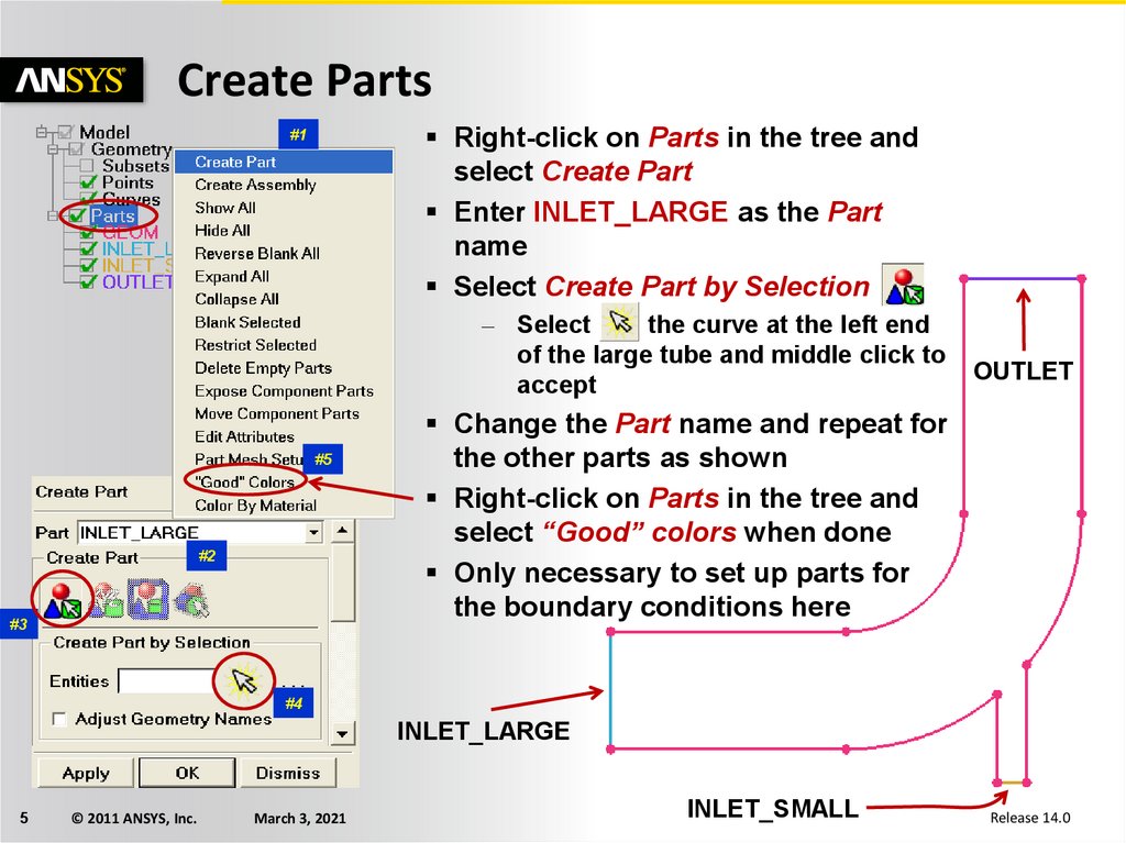
Create PartsRight-click on Parts in the tree and
select Create Part
Enter INLET_LARGE as the Part
name
Select Create Part by Selection
#1
– Select
the curve at the left end
of the large tube and middle click to
accept
#5
#2
#3
OUTLET
Change the Part name and repeat for
the other parts as shown
Right-click on Parts in the tree and
select “Good” colors when done
Only necessary to set up parts for
the boundary conditions here
#4
INLET_LARGE
5
© 2011 ANSYS, Inc.
March 3, 2021
INLET_SMALL
Release 14.0
6.
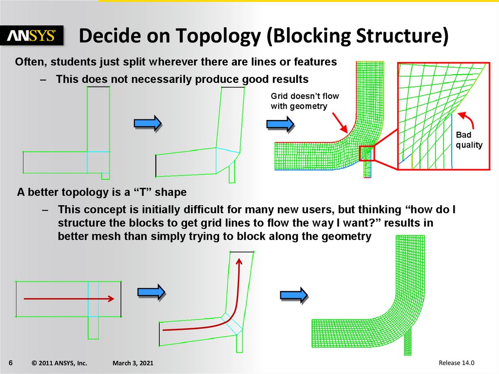
Decide on Topology (Blocking Structure)Often, students just split wherever there are lines or features
– This does not necessarily produce good results
Grid doesn’t flow
with geometry
Bad
quality
A better topology is a “T” shape
– This concept is initially difficult for many new users, but thinking “how do I
structure the blocks to get grid lines to flow the way I want?” results in
better mesh than simply trying to block along the geometry
6
© 2011 ANSYS, Inc.
March 3, 2021
Release 14.0
7.
Initialize Blocking#1
#3
#2
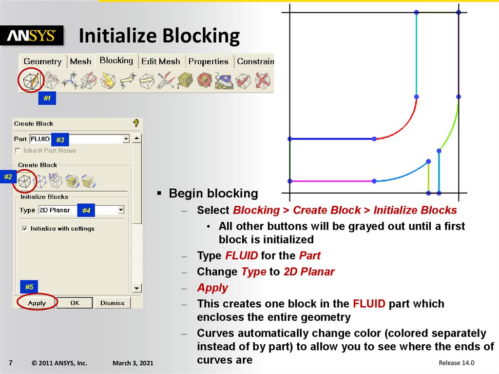
Begin blocking
#4
#5
7
© 2011 ANSYS, Inc.
March 3, 2021
– Select Blocking > Create Block > Initialize Blocks
• All other buttons will be grayed out until a first
block is initialized
– Type FLUID for the Part
– Change Type to 2D Planar
– Apply
– This creates one block in the FLUID part which
encloses the entire geometry
– Curves automatically change color (colored separately
instead of by part) to allow you to see where the ends of
curves are
Release 14.0
8.
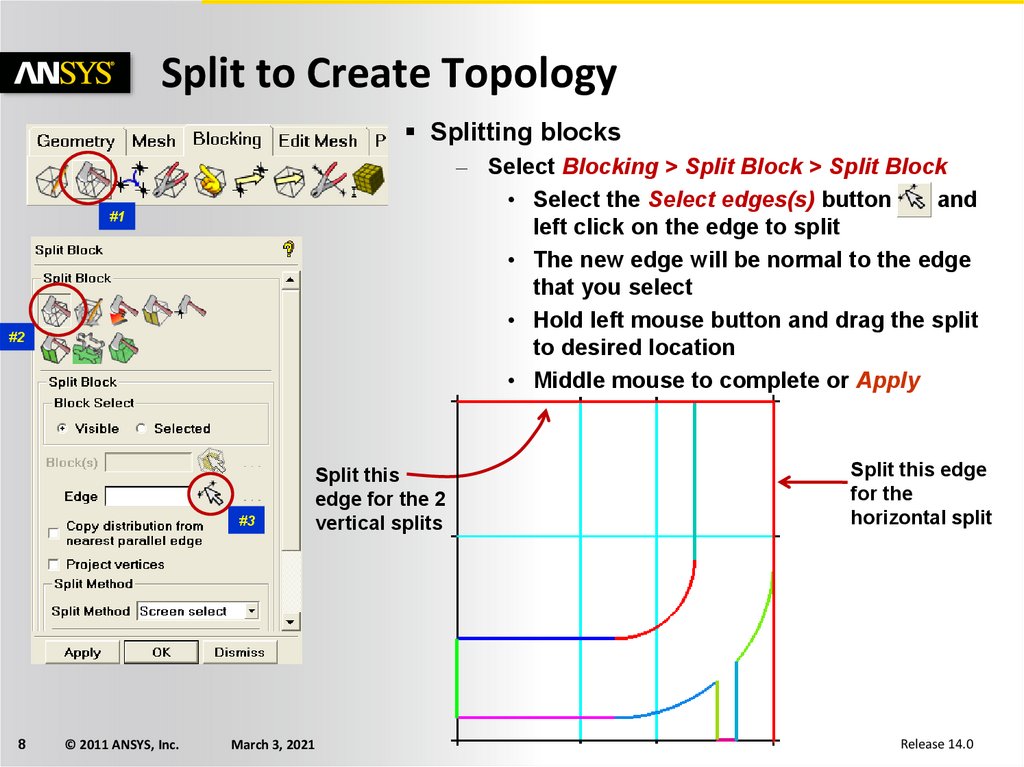
Split to Create TopologySplitting blocks
– Select Blocking > Split Block > Split Block
• Select the Select edges(s) button
and
left click on the edge to split
• The new edge will be normal to the edge
that you select
• Hold left mouse button and drag the split
to desired location
• Middle mouse to complete or Apply
#1
#2
#3
8
© 2011 ANSYS, Inc.
March 3, 2021
Split this
edge for the 2
vertical splits
Split this edge
for the
horizontal split
Release 14.0
9.
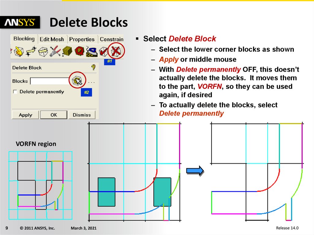
Delete BlocksSelect Delete Block
#1
#2
– Select the lower corner blocks as shown
– Apply or middle mouse
– With Delete permanently OFF, this doesn’t
actually delete the blocks. It moves them
to the part, VORFN, so they can be used
again, if desired
– To actually delete the blocks, select
Delete permanently
VORFN region
9
© 2011 ANSYS, Inc.
March 3, 2021
Release 14.0
10.
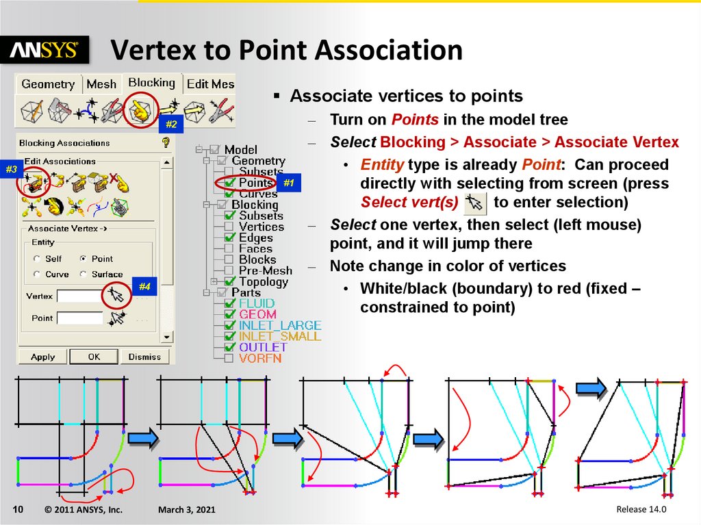
Vertex to Point AssociationAssociate vertices to points
#2
#3
#1
#4
10
© 2011 ANSYS, Inc.
March 3, 2021
– Turn on Points in the model tree
– Select Blocking > Associate > Associate Vertex
• Entity type is already Point: Can proceed
directly with selecting from screen (press
Select vert(s)
to enter selection)
– Select one vertex, then select (left mouse)
point, and it will jump there
– Note change in color of vertices
• White/black (boundary) to red (fixed –
constrained to point)
Release 14.0
11.
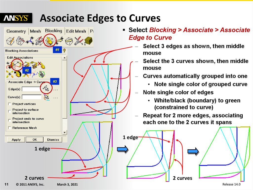
Associate Edges to CurvesSelect Blocking > Associate > Associate
Edge to Curve
#1
#2
#3
– Select 3 edges as shown, then middle
mouse
– Select the 3 curves shown, then middle
mouse
– Curves automatically grouped into one
• Note single color of grouped curve
– Note single color of edges
• White/black (boundary) to green
(constrained to curve)
– Repeat for 2 more edges, associating
each one to the 2 curves it spans
1 edge
1 edge
2 curves
11
© 2011 ANSYS, Inc.
2 curves
March 3, 2021
Release 14.0
12.
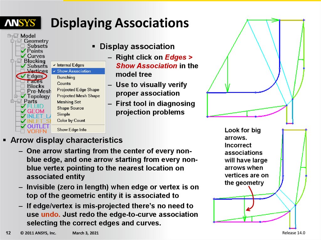
Displaying AssociationsDisplay association
– Right click on Edges >
Show Association in the
model tree
– Use to visually verify
proper association
– First tool in diagnosing
projection problems
Arrow display characteristics
– One arrow starting from the center of every nonblue edge, and one arrow starting from every nonblue vertex pointing to the nearest location on
associated entity
– Invisible (zero in length) when edge or vertex is on
top of the geometric entity it is associated to
– If edge/vertex is mis-projected there’s no need to
use undo. Just redo the edge-to-curve association
selecting the correct edges and curves.
12
© 2011 ANSYS, Inc.
March 3, 2021
Look for big
arrows.
Incorrect
associations
will have large
arrows when
vertices are on
the geometry
Release 14.0
13.
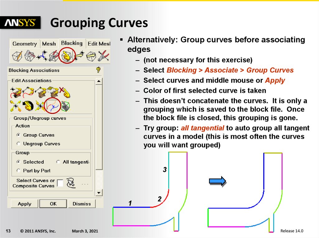
Grouping CurvesAlternatively: Group curves before associating
edges
–
–
–
–
–
(not necessary for this exercise)
Select Blocking > Associate > Group Curves
Select curves and middle mouse or Apply
Color of first selected curve is taken
This doesn’t concatenate the curves. It is only a
grouping which is saved to the block file. Once
the block file is closed, this grouping is gone.
– Try group: all tangential to auto group all tangent
curves in a model (this is most often the curves
you will want grouped)
3
1
13
© 2011 ANSYS, Inc.
March 3, 2021
2
Release 14.0
14.
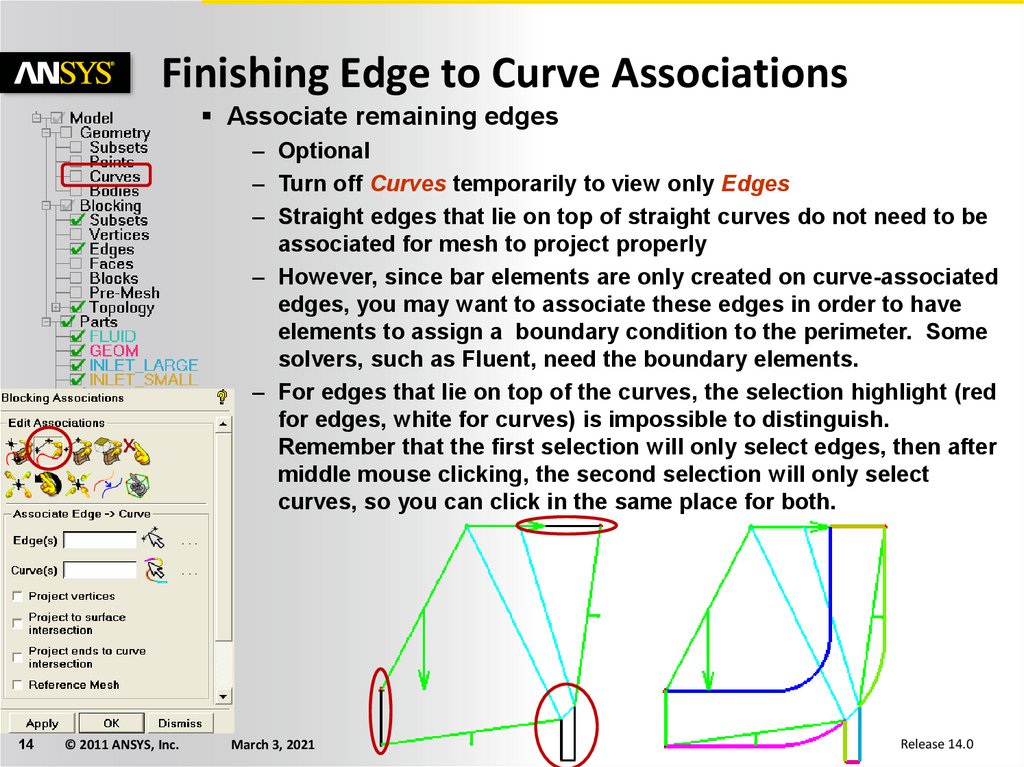
Finishing Edge to Curve AssociationsAssociate remaining edges
– Optional
– Turn off Curves temporarily to view only Edges
– Straight edges that lie on top of straight curves do not need to be
associated for mesh to project properly
– However, since bar elements are only created on curve-associated
edges, you may want to associate these edges in order to have
elements to assign a boundary condition to the perimeter. Some
solvers, such as Fluent, need the boundary elements.
– For edges that lie on top of the curves, the selection highlight (red
for edges, white for curves) is impossible to distinguish.
Remember that the first selection will only select edges, then after
middle mouse clicking, the second selection will only select
curves, so you can click in the same place for both.
14
© 2011 ANSYS, Inc.
March 3, 2021
Release 14.0
15.
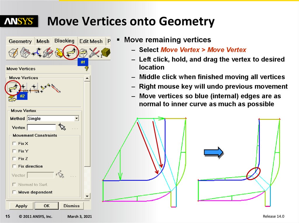
Move Vertices onto GeometryMove remaining vertices
#1
#2
15
© 2011 ANSYS, Inc.
March 3, 2021
– Select Move Vertex > Move Vertex
– Left click, hold, and drag the vertex to desired
location
– Middle click when finished moving all vertices
– Right mouse key will undo previous movement
– Move vertices so blue (internal) edges are as
normal to inner curve as much as possible
Release 14.0
16.
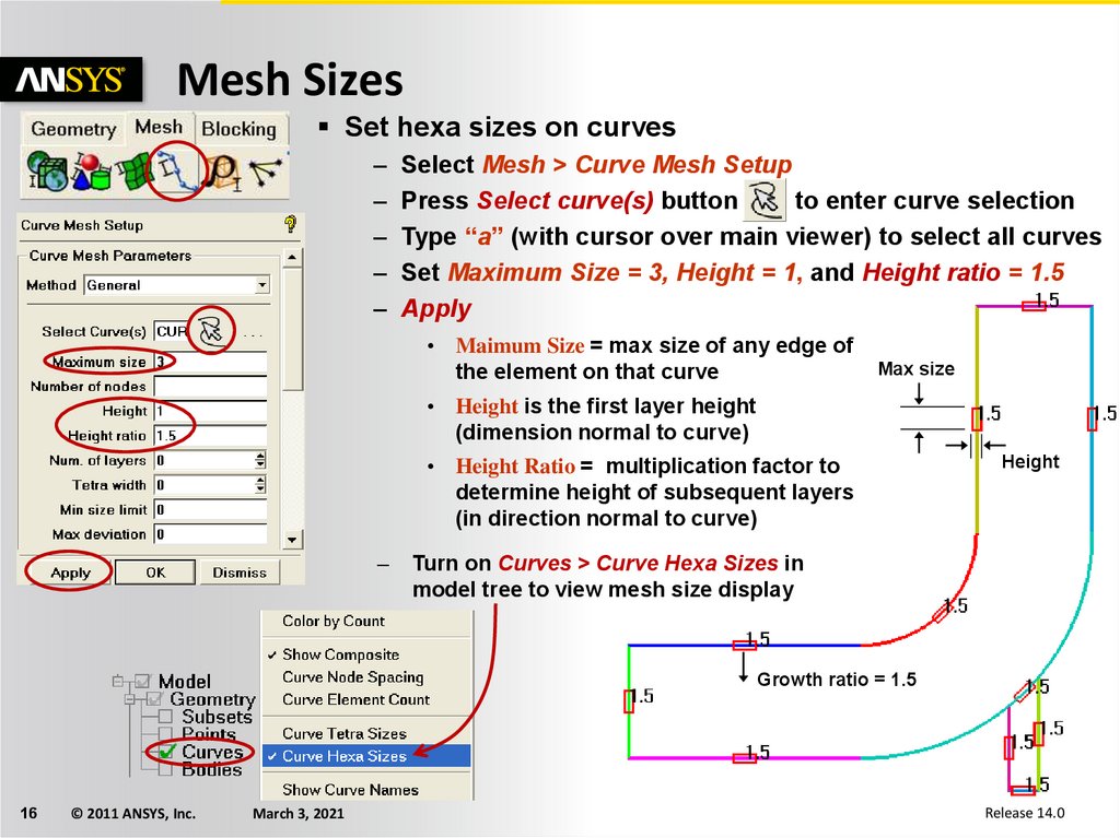
Mesh SizesSet hexa sizes on curves
–
–
–
–
–
Select Mesh > Curve Mesh Setup
Press Select curve(s) button
to enter curve selection
Type “a” (with cursor over main viewer) to select all curves
Set Maximum Size = 3, Height = 1, and Height ratio = 1.5
Apply
• Maimum Size = max size of any edge of
the element on that curve
Max size
• Height is the first layer height
(dimension normal to curve)
• Height Ratio = multiplication factor to
determine height of subsequent layers
(in direction normal to curve)
–
Height
Turn on Curves > Curve Hexa Sizes in
model tree to view mesh size display
Growth ratio = 1.5
16
© 2011 ANSYS, Inc.
March 3, 2021
Release 14.0
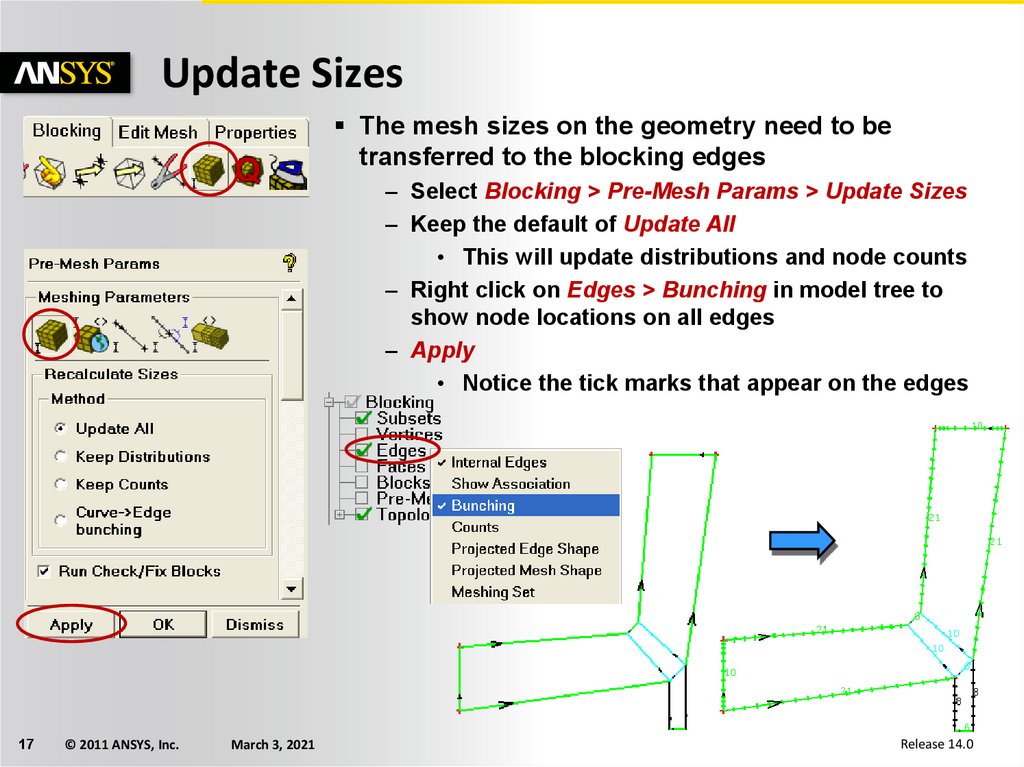
17.
Update SizesThe mesh sizes on the geometry need to be
transferred to the blocking edges
– Select Blocking > Pre-Mesh Params > Update Sizes
– Keep the default of Update All
• This will update distributions and node counts
– Right click on Edges > Bunching in model tree to
show node locations on all edges
– Apply
• Notice the tick marks that appear on the edges
17
© 2011 ANSYS, Inc.
March 3, 2021
Release 14.0
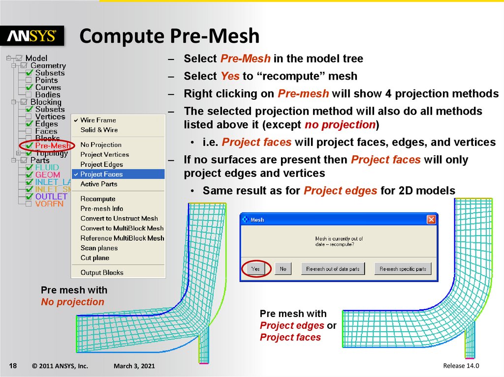
18.
Compute Pre-Mesh– Select Pre-Mesh in the model tree
– Select Yes to “recompute” mesh
– Right clicking on Pre-mesh will show 4 projection methods
– The selected projection method will also do all methods
listed above it (except no projection)
• i.e. Project faces will project faces, edges, and vertices
– If no surfaces are present then Project faces will only
project edges and vertices
• Same result as for Project edges for 2D models
Pre mesh with
No projection
Pre mesh with
Project edges or
Project faces
18
© 2011 ANSYS, Inc.
March 3, 2021
Release 14.0
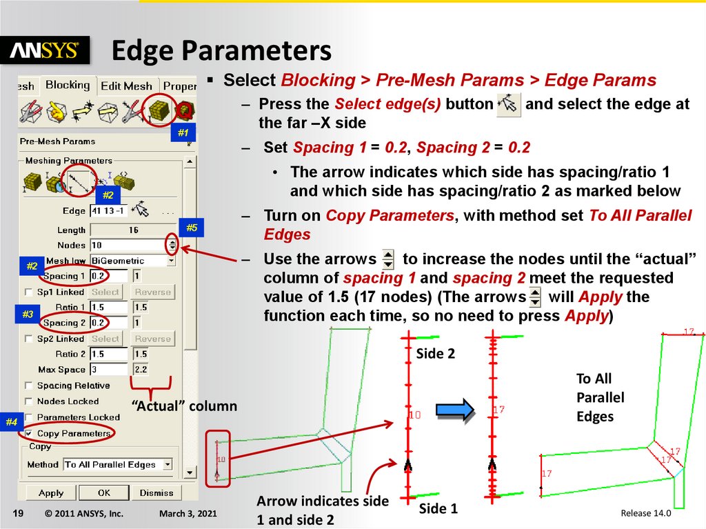
19.
Edge ParametersSelect Blocking > Pre-Mesh Params > Edge Params
#1
– Press the Select edge(s) button
the far –X side
and select the edge at
– Set Spacing 1 = 0.2, Spacing 2 = 0.2
• The arrow indicates which side has spacing/ratio 1
and which side has spacing/ratio 2 as marked below
#2
#5
– Turn on Copy Parameters, with method set To All Parallel
Edges
– Use the arrows
to increase the nodes until the “actual”
column of spacing 1 and spacing 2 meet the requested
value of 1.5 (17 nodes) (The arrows will Apply the
function each time, so no need to press Apply)
#2
#3
Side 2
To All
Parallel
Edges
“Actual” column
#4
19
© 2011 ANSYS, Inc.
March 3, 2021
Arrow indicates side
1 and side 2
Side 1
Release 14.0
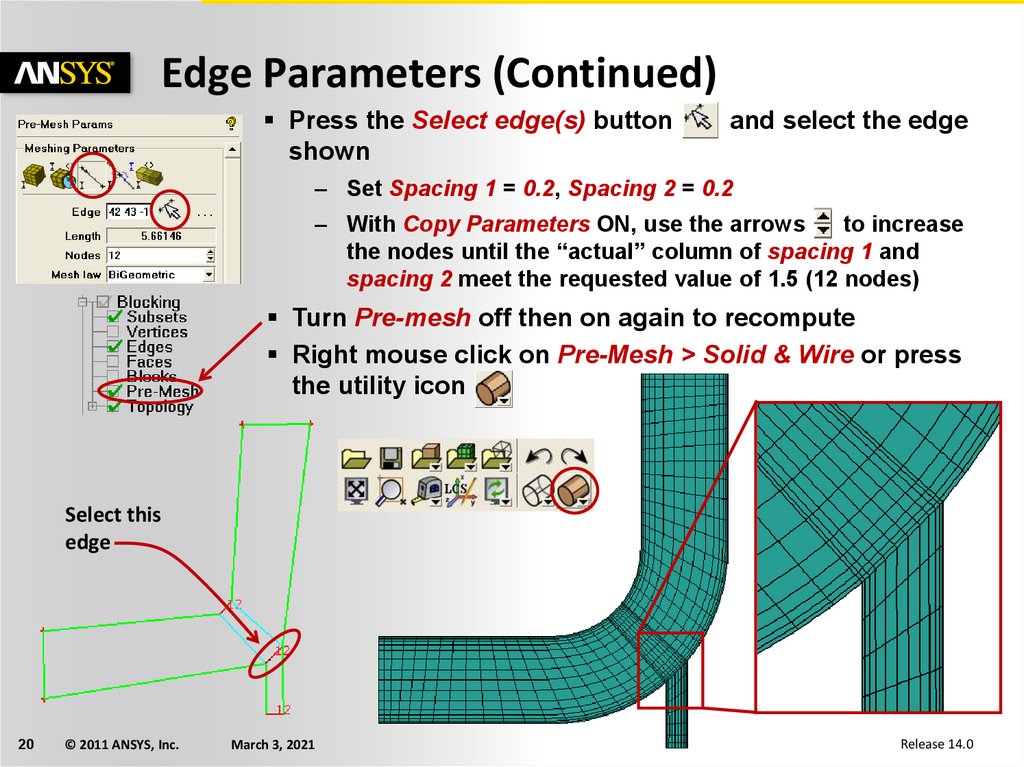
20.
Edge Parameters (Continued)Press the Select edge(s) button
shown
and select the edge
– Set Spacing 1 = 0.2, Spacing 2 = 0.2
– With Copy Parameters ON, use the arrows
to increase
the nodes until the “actual” column of spacing 1 and
spacing 2 meet the requested value of 1.5 (12 nodes)
Turn Pre-mesh off then on again to recompute
Right mouse click on Pre-Mesh > Solid & Wire or press
the utility icon
Select this
edge
20
© 2011 ANSYS, Inc.
March 3, 2021
Release 14.0
21.
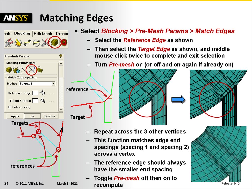
Matching EdgesSelect Blocking > Pre-Mesh Params > Match Edges
– Select the Reference Edge as shown
– Then select the Target Edge as shown, and middle
mouse click twice to complete and exit selection
– Turn Pre-mesh on (or off and on again if already on)
reference
Target
Targets
– Repeat across the 3 other vertices
– This function matches edge end
spacings (spacing 1 and spacing 2)
across a vertex
– The reference edge should always
have the smaller end spacing
references
21
© 2011 ANSYS, Inc.
March 3, 2021
– Toggle Pre-mesh off then on to
recompute
Release 14.0
22.
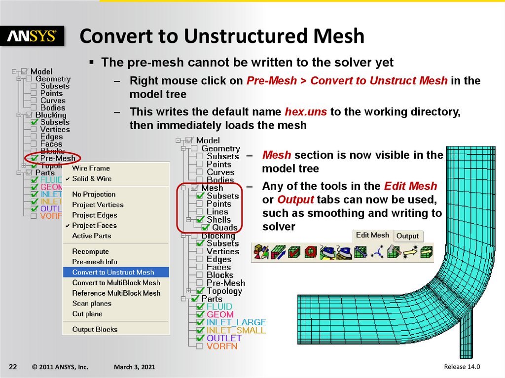
Convert to Unstructured MeshThe pre-mesh cannot be written to the solver yet
– Right mouse click on Pre-Mesh > Convert to Unstruct Mesh in the
model tree
– This writes the default name hex.uns to the working directory,
then immediately loads the mesh
– Mesh section is now visible in the
model tree
– Any of the tools in the Edit Mesh
or Output tabs can now be used,
such as smoothing and writing to
solver
22
© 2011 ANSYS, Inc.
March 3, 2021
Release 14.0
23.
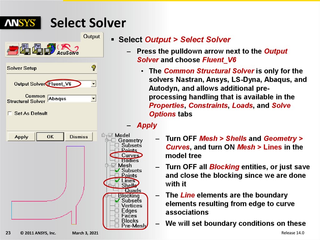
Select SolverSelect Output > Select Solver
– Press the pulldown arrow next to the Output
Solver and choose Fluent_V6
• The Common Structural Solver is only for the
solvers Nastran, Ansys, LS-Dyna, Abaqus, and
Autodyn, and allows additional preprocessing handling that is available in the
Properties, Constraints, Loads, and Solve
Options tabs
– Apply
– Turn OFF Mesh > Shells and Geometry >
Curves, and turn ON Mesh > Lines in the
model tree
– Turn OFF all Blocking entities, or just save
and close the blocking since we are done
with it
– The Line elements are the boundary
elements resulting from edge to curve
associations
– We will set boundary conditions on these
23
© 2011 ANSYS, Inc.
March 3, 2021
Release 14.0
24.
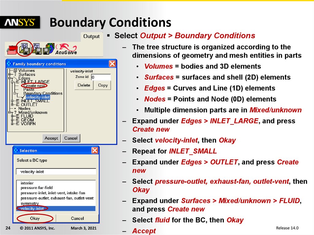
Boundary ConditionsSelect Output > Boundary Conditions
– The tree structure is organized according to the
dimensions of geometry and mesh entities in parts
• Volumes = bodies and 3D elements
• Surfaces = surfaces and shell (2D) elements
• Edges = Curves and Line (1D) elements
• Nodes = Points and Node (0D) elements
• Multiple dimension parts are in Mixed/unknown
– Expand under Edges > INLET_LARGE, and press
Create new
– Select velocity-inlet, then Okay
– Repeat for INLET_SMALL
– Expand under Edges > OUTLET, and press Create
new
– Select pressure-outlet, exhaust-fan, outlet-vent, then
Okay
– Expand under Surfaces > Mixed/unknown > FLUID,
and press Create new
– Select fluid for the BC, then Okay
24
© 2011 ANSYS, Inc.
March 3, 2021
– Accept
Release 14.0
25.
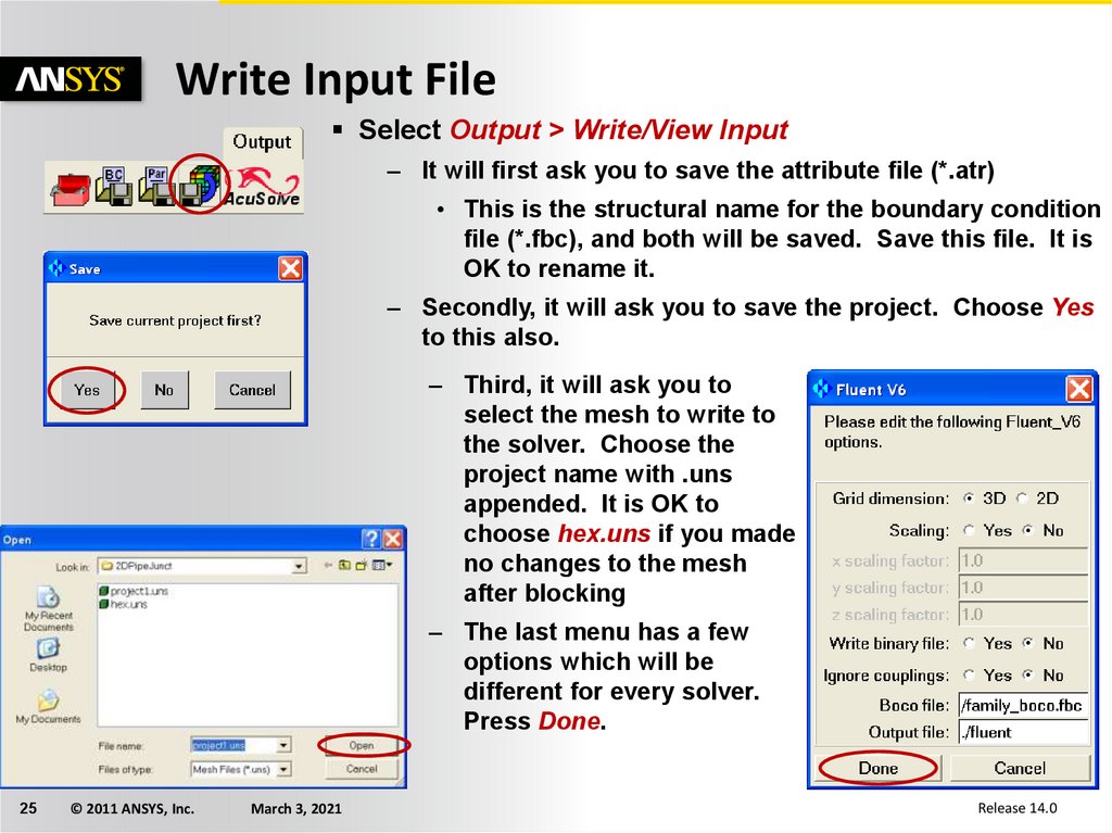
Write Input FileSelect Output > Write/View Input
– It will first ask you to save the attribute file (*.atr)
• This is the structural name for the boundary condition
file (*.fbc), and both will be saved. Save this file. It is
OK to rename it.
– Secondly, it will ask you to save the project. Choose Yes
to this also.
– Third, it will ask you to
select the mesh to write to
the solver. Choose the
project name with .uns
appended. It is OK to
choose hex.uns if you made
no changes to the mesh
after blocking
– The last menu has a few
options which will be
different for every solver.
Press Done.
25
© 2011 ANSYS, Inc.
March 3, 2021
Release 14.0