 Программное обеспечение
Похожие презентации:


Workshop 8.3 3D Pipe Junction O-grid
1.
Workshop 8.33D Pipe Junction O-grid
14. 0 Release
Introduction to ANSYS
ICEM CFD
1
© 2011 ANSYS, Inc.
March 19, 2021
Release 14.0
2.
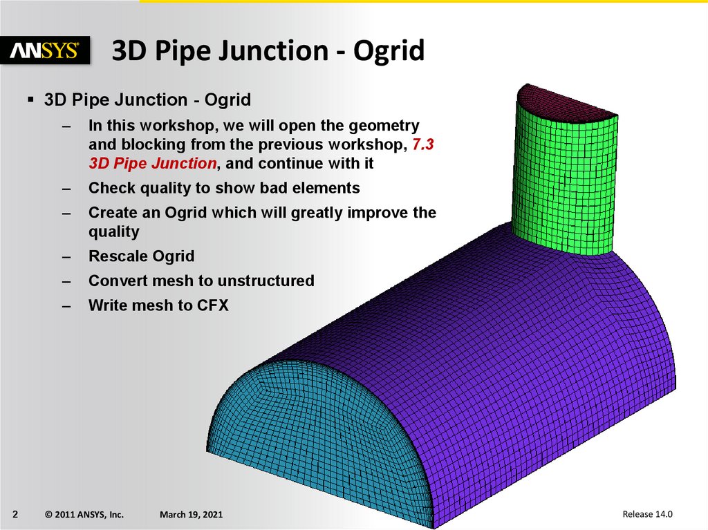
3D Pipe Junction - Ogrid3D Pipe Junction - Ogrid
2
–
In this workshop, we will open the geometry
and blocking from the previous workshop, 7.3
3D Pipe Junction, and continue with it
–
Check quality to show bad elements
–
Create an Ogrid which will greatly improve the
quality
–
Rescale Ogrid
–
Convert mesh to unstructured
–
Write mesh to CFX
© 2011 ANSYS, Inc.
March 19, 2021
Release 14.0
3.
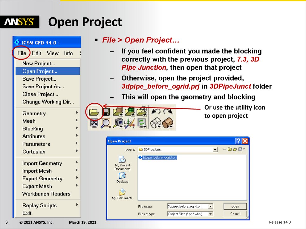
Open ProjectFile > Open Project…
3
© 2011 ANSYS, Inc.
March 19, 2021
–
If you feel confident you made the blocking
correctly with the previous project, 7.3, 3D
Pipe Junction, then open that project
–
Otherwise, open the project provided,
3dpipe_before_ogrid.prj in 3DPipeJunct folder
–
This will open the geometry and blocking
Or use the utility icon
to open project
Release 14.0
4.
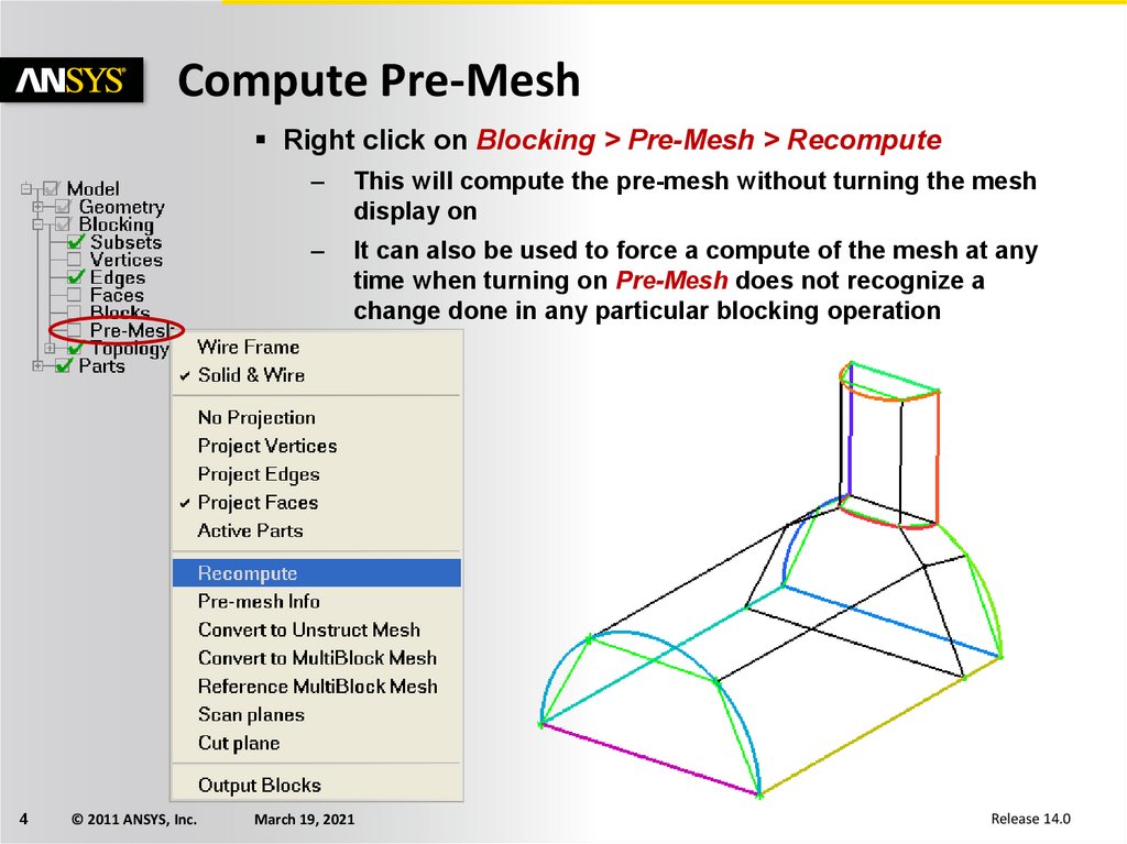
Compute Pre-MeshRight click on Blocking > Pre-Mesh > Recompute
4
© 2011 ANSYS, Inc.
–
This will compute the pre-mesh without turning the mesh
display on
–
It can also be used to force a compute of the mesh at any
time when turning on Pre-Mesh does not recognize a
change done in any particular blocking operation
March 19, 2021
Release 14.0
5.
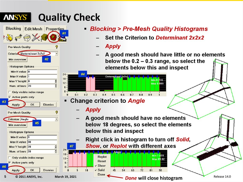
Quality CheckBlocking > Pre-Mesh Quality Histograms
#1
–
Set the Criterion to Determinant 2x2x2
–
Apply
–
A good mesh should have little or no elements
below the 0.2 – 0.3 range, so select the
elements below this and inspect
#2
#4
Change criterion to Angle
#3
–
Apply
–
A good mesh should have no elements
below 18 degrees, so select the elements
below this and inspect
–
Right click in histogram to turn off Solid,
Show, or Replot with different axes
#5
#7
#6
5
© 2011 ANSYS, Inc.
March 19, 2021
Done will close histogram
Release 14.0
6.
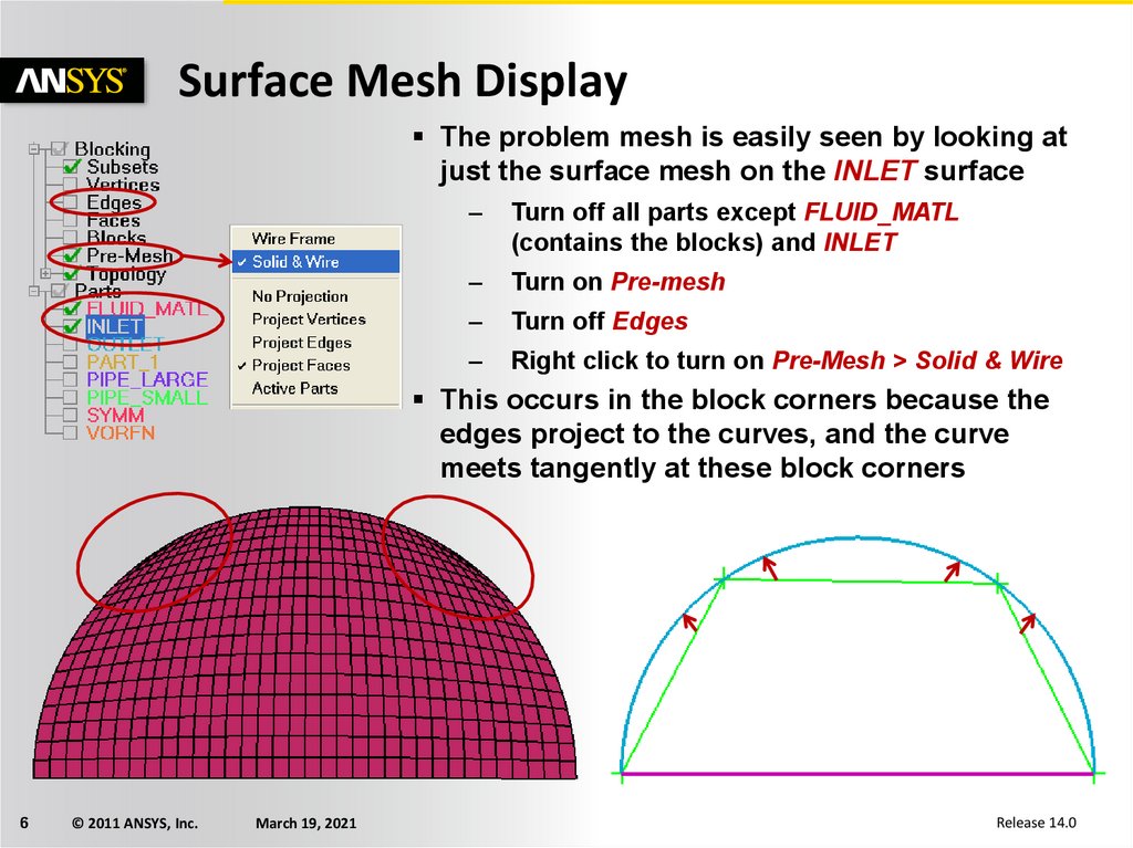
Surface Mesh DisplayThe problem mesh is easily seen by looking at
just the surface mesh on the INLET surface
–
Turn off all parts except FLUID_MATL
(contains the blocks) and INLET
–
Turn on Pre-mesh
–
Turn off Edges
–
Right click to turn on Pre-Mesh > Solid & Wire
This occurs in the block corners because the
edges project to the curves, and the curve
meets tangently at these block corners
6
© 2011 ANSYS, Inc.
March 19, 2021
Release 14.0
7.
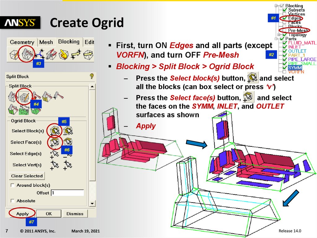
Create Ogrid#1
First, turn ON Edges and all parts (except
#2
VORFN), and turn OFF Pre-Mesh
Blocking > Split Block > Ogrid Block
#3
–
Press the Select block(s) button,
and select
all the blocks (can box select or press ‘v’)
–
Press the Select face(s) button,
and select
the faces on the SYMM, INLET, and OUTLET
surfaces as shown
–
Apply
#4
#5
#6
#7
7
© 2011 ANSYS, Inc.
March 19, 2021
Release 14.0
8.
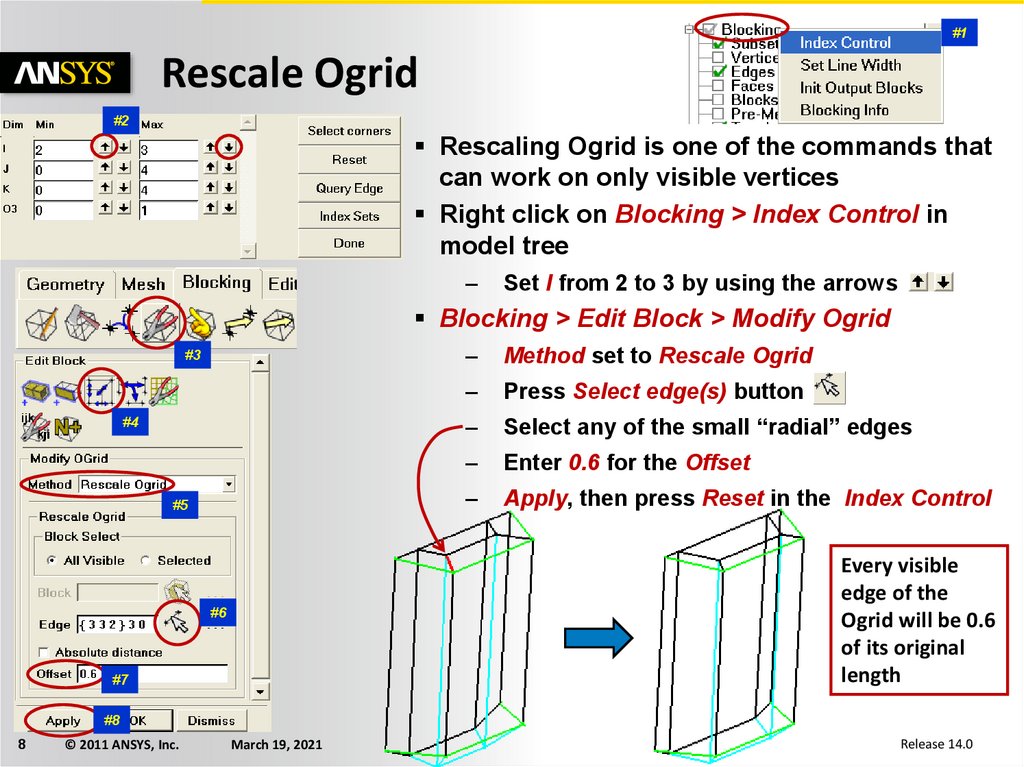
#1Rescale Ogrid
#2
Rescaling Ogrid is one of the commands that
can work on only visible vertices
Right click on Blocking > Index Control in
model tree
–
Set I from 2 to 3 by using the arrows
Blocking > Edit Block > Modify Ogrid
#3
#4
#5
–
Method set to Rescale Ogrid
–
Press Select edge(s) button
–
Select any of the small “radial” edges
–
Enter 0.6 for the Offset
–
Apply, then press Reset in the Index Control
Every visible
edge of the
Ogrid will be 0.6
of its original
length
#6
#7
#8
8
© 2011 ANSYS, Inc.
March 19, 2021
Release 14.0
9.
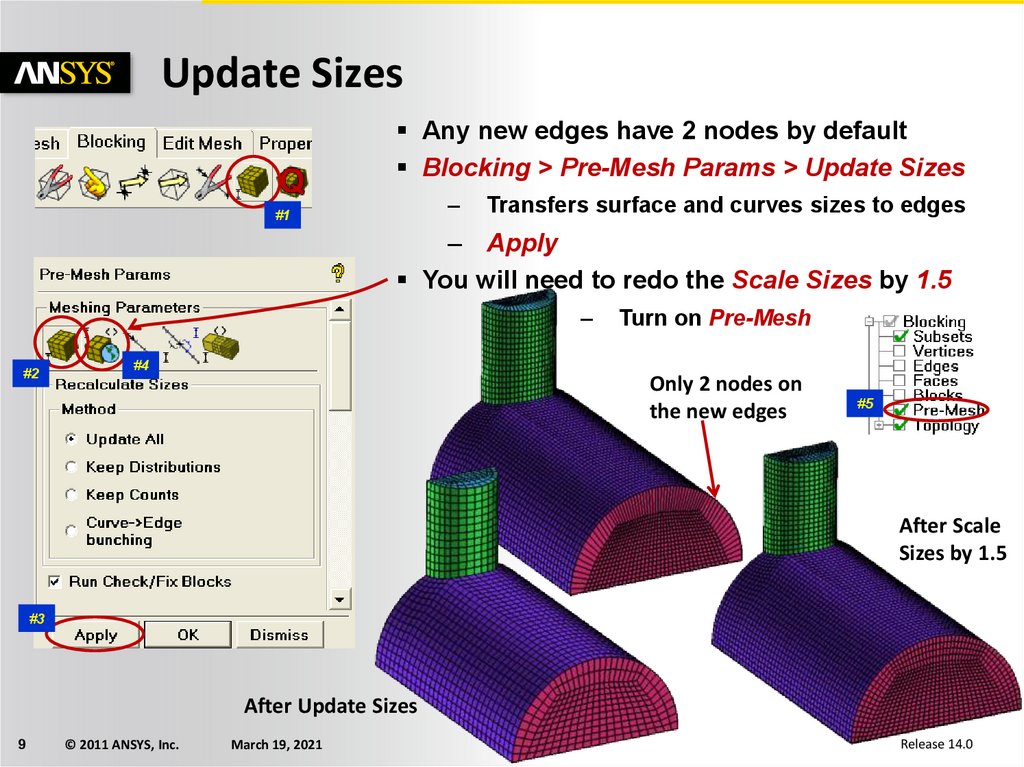
Update SizesAny new edges have 2 nodes by default
Blocking > Pre-Mesh Params > Update Sizes
–
#1
Transfers surface and curves sizes to edges
– Apply
You will need to redo the Scale Sizes by 1.5
–
#2
Turn on Pre-Mesh
#4
Only 2 nodes on
the new edges
#5
After Scale
Sizes by 1.5
#3
After Update Sizes
9
© 2011 ANSYS, Inc.
March 19, 2021
Release 14.0
10.
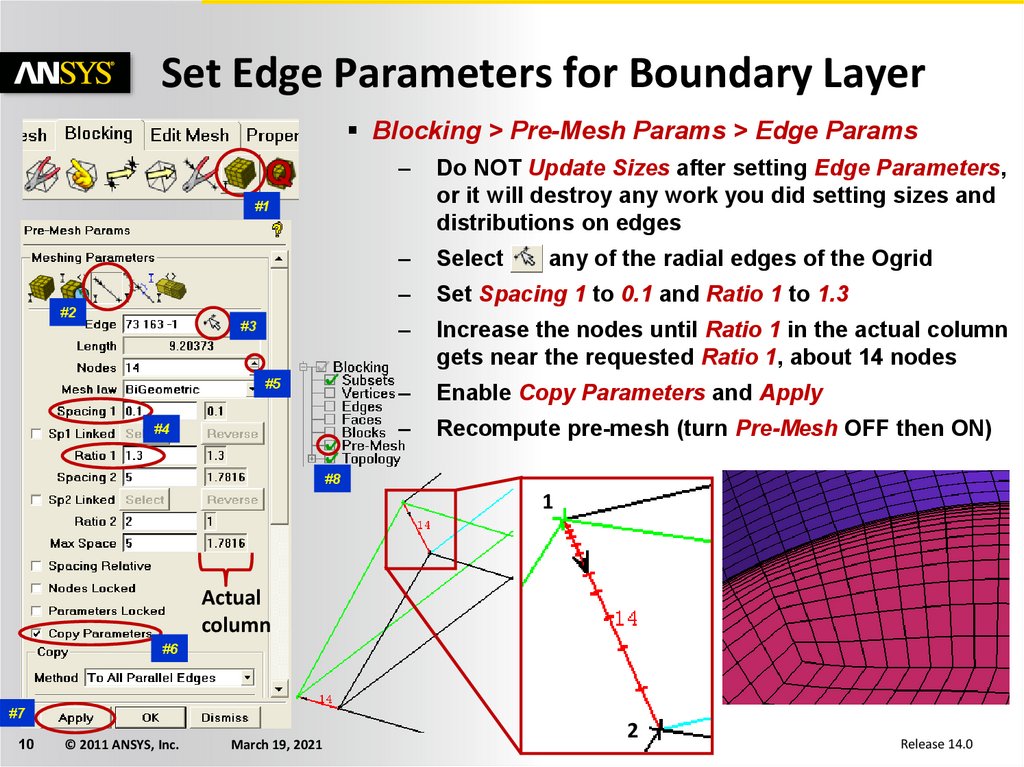
Set Edge Parameters for Boundary LayerBlocking > Pre-Mesh Params > Edge Params
–
Do NOT Update Sizes after setting Edge Parameters,
or it will destroy any work you did setting sizes and
distributions on edges
–
Select
–
Set Spacing 1 to 0.1 and Ratio 1 to 1.3
–
Increase the nodes until Ratio 1 in the actual column
gets near the requested Ratio 1, about 14 nodes
–
Enable Copy Parameters and Apply
–
Recompute pre-mesh (turn Pre-Mesh OFF then ON)
#1
#2
#3
#5
#4
any of the radial edges of the Ogrid
#8
1
Actual
column
#6
#7
10
© 2011 ANSYS, Inc.
March 19, 2021
2
Release 14.0
11.
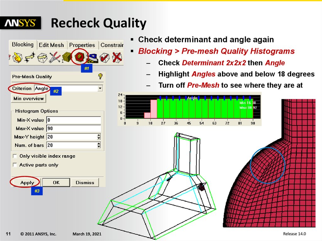
Recheck QualityCheck determinant and angle again
Blocking > Pre-mesh Quality Histograms
#1
–
Check Determinant 2x2x2 then Angle
–
Highlight Angles above and below 18 degrees
–
Turn off Pre-Mesh to see where they are at
#2
#3
11
© 2011 ANSYS, Inc.
March 19, 2021
Release 14.0
12.
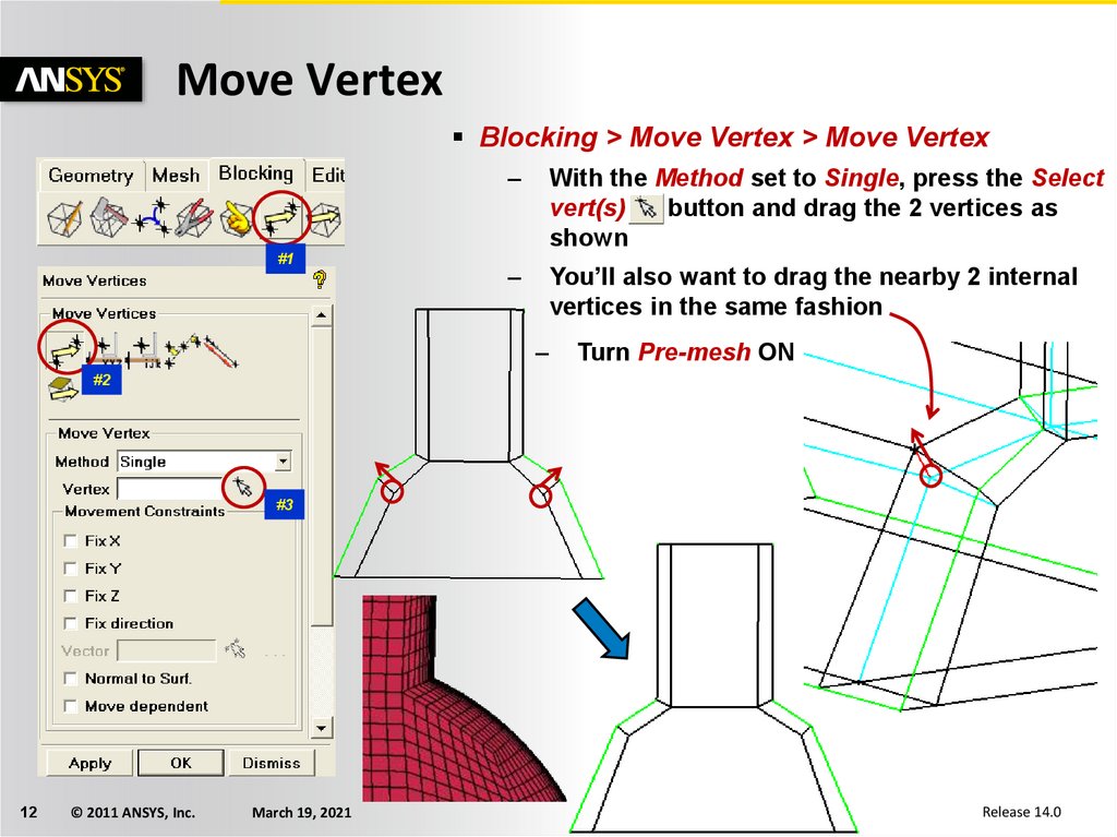
Move VertexBlocking > Move Vertex > Move Vertex
#1
–
With the Method set to Single, press the Select
vert(s)
button and drag the 2 vertices as
shown
–
You’ll also want to drag the nearby 2 internal
vertices in the same fashion
–
Turn Pre-mesh ON
#2
#3
12
© 2011 ANSYS, Inc.
March 19, 2021
Release 14.0
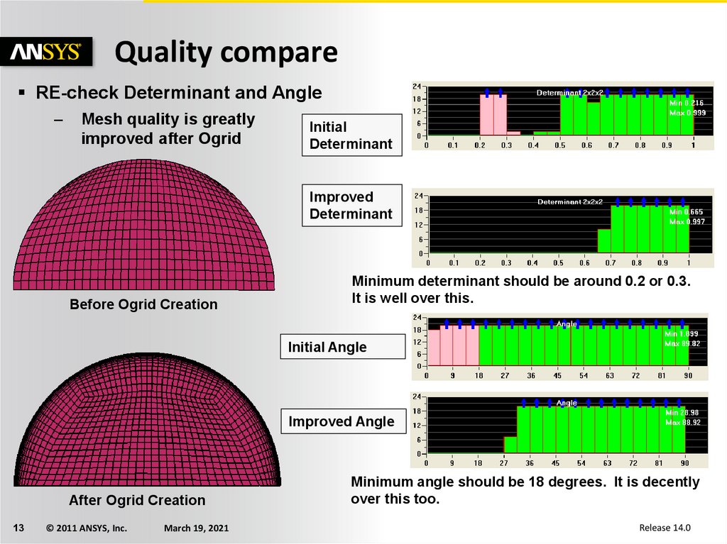
13.
Quality compareRE-check Determinant and Angle
–
Mesh quality is greatly
improved after Ogrid
Initial
Determinant
Improved
Determinant
Before Ogrid Creation
Minimum determinant should be around 0.2 or 0.3.
It is well over this.
Initial Angle
Improved Angle
After Ogrid Creation
13
© 2011 ANSYS, Inc.
March 19, 2021
Minimum angle should be 18 degrees. It is decently
over this too.
Release 14.0
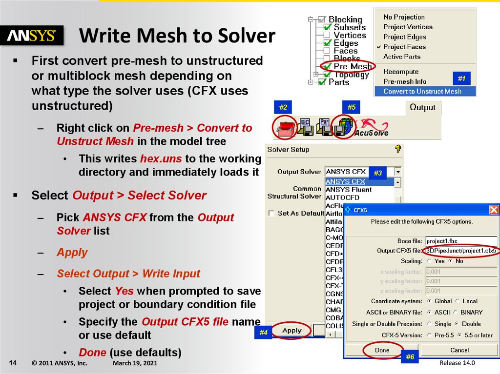
14.
Write Mesh to SolverFirst convert pre-mesh to unstructured
or multiblock mesh depending on
what type the solver uses (CFX uses
unstructured)
–
14
#2
#5
Right click on Pre-mesh > Convert to
Unstruct Mesh in the model tree
#1
This writes hex.uns to the working
directory and immediately loads it
#3
Select Output > Select Solver
–
Pick ANSYS CFX from the Output
Solver list
–
Apply
–
Select Output > Write Input
Select Yes when prompted to save
project or boundary condition file
Specify the Output CFX5 file name
#4
or use default
Done (use defaults)
© 2011 ANSYS, Inc.
March 19, 2021
#6
Release 14.0