


 Электроника
 Промышленность
Похожие презентации:


Protection – passive coherent location radar, radio monitoring and anti-uav system
1.
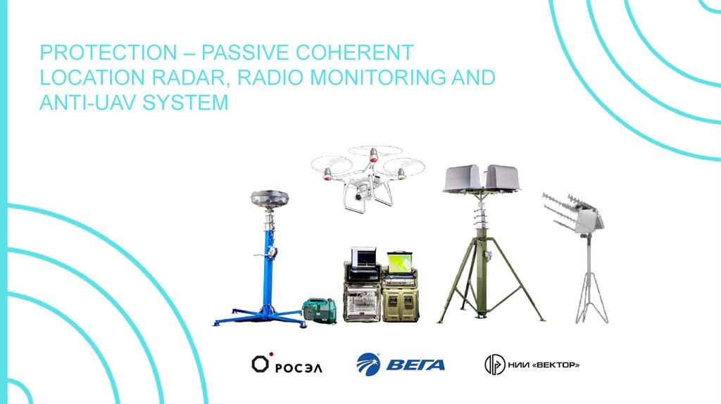
PROTECTION – PASSIVE COHERENTLOCATION RADAR, RADIO MONITORING AND
ANTI-UAV SYSTEM
2.
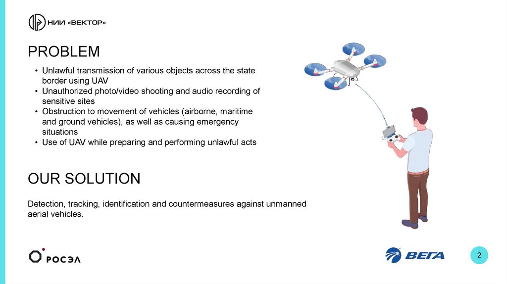
PROBLEM• Unlawful transmission of various objects across the state
border using UAV
• Unauthorized photo/video shooting and audio recording of
sensitive sites
• Obstruction to movement of vehicles (airborne, maritime
and ground vehicles), as well as causing emergency
situations
• Use of UAV while preparing and performing unlawful acts
OUR SOLUTION
Detection, tracking, identification and countermeasures against unmanned
aerial vehicles.
2
3.
TASKS PERFORMEDA
B
C
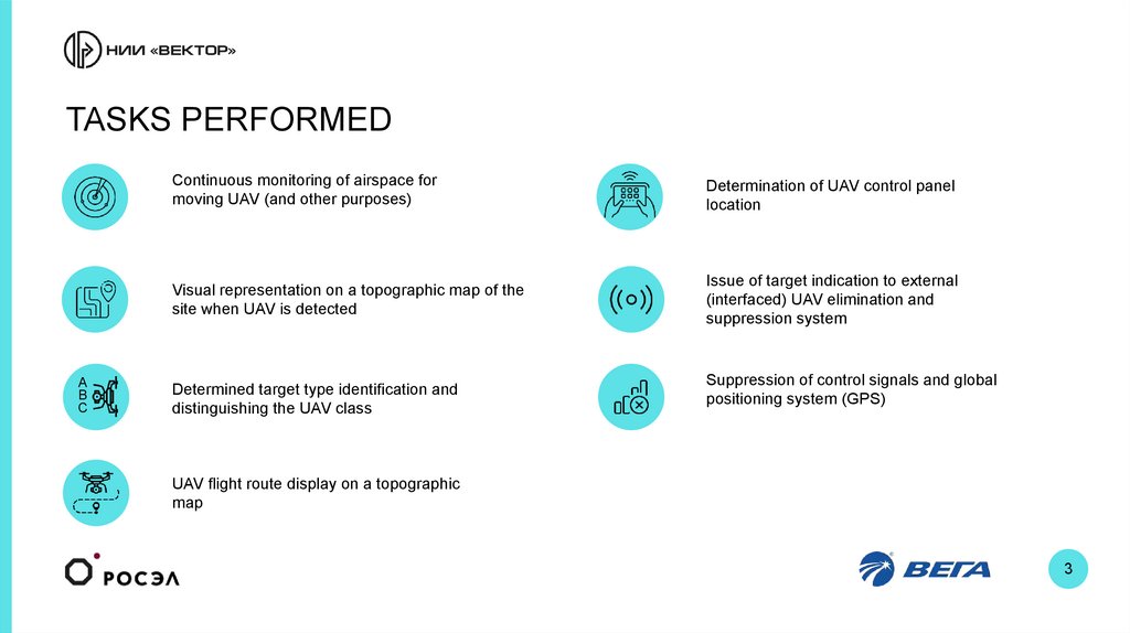
Continuous monitoring of airspace for
moving UAV (and other purposes)
Determination of UAV control panel
location
Visual representation on a topographic map of the
site when UAV is detected
Issue of target indication to external
(interfaced) UAV elimination and
suppression system
Determined target type identification and
distinguishing the UAV class
Suppression of control signals and global
positioning system (GPS)
UAV flight route display on a topographic
map
3
4.
KEY SITES THAT NEED PROTECTION FROM UAVStadiums
Airports
Pоrts
Chemical plants
Hydropower plants
Nuclear power plants
Oil and gas
infrastructure
Oil and
gas lines
Corrective labour
institutions
Social
infrastructure
4
5.
ADVANTAGES OF THE SYSTEMMobility – the system is implemented on the
basis of portable case containers and can
be placed at any location
System deployment time not more
than 30 minutes
Detects location of UAV and remote control
panel
Displays UAV route on a topographic map
Operates in passive mode, no active
radiation
Year-round operation in any weather
conditions
Can be interfaced with UAV
suppression and elimination equipment
No EMI effect on infrastructure of the
monitored site
Selective action against
intruder drone
Coverage area –
360 degrees
5
6.
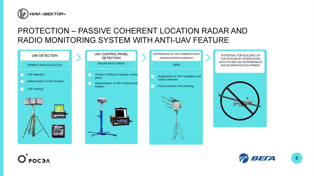
PROTECTION – PASSIVE COHERENT LOCATION RADAR ANDRADIO MONITORING SYSTEM WITH ANTI-UAV FEATURE
UAV DETECTION
PASSIVE RADIOLACATION
UAV detection
Determination of UAV location
UAV tracking
UAV CONTROL PANEL
DETECTION
RADAR MONITORING
Direction finding of operator control
panel
Determination of UAV control panel
location
SUPPRESSION OF UAV COMMUNICATION
AND NAVIGATION CHANNELS
SERP
POTENTIAL FOR BUILDING UP
THE SYSTEM BY INTERFACING
WITH OTHER UAV SUPPRESSION
AND ELIMINATION EQUIPMENT
Suppression of UAV navigation and
control channels
Corner (sector) UAV jamming
6
7.
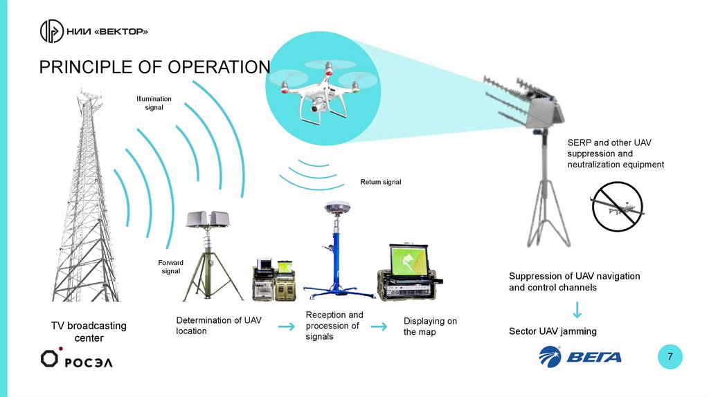
PRINCIPLE OF OPERATIONIllumination
signal
SERP and other UAV
suppression and
neutralization equipment
Return signal
Forward
signal
TV broadcasting
center
Determination of UAV
location
Suppression of UAV navigation
and control channels
Reception and
procession of
signals
Displaying on
the map
Sector UAV jamming
7
8.
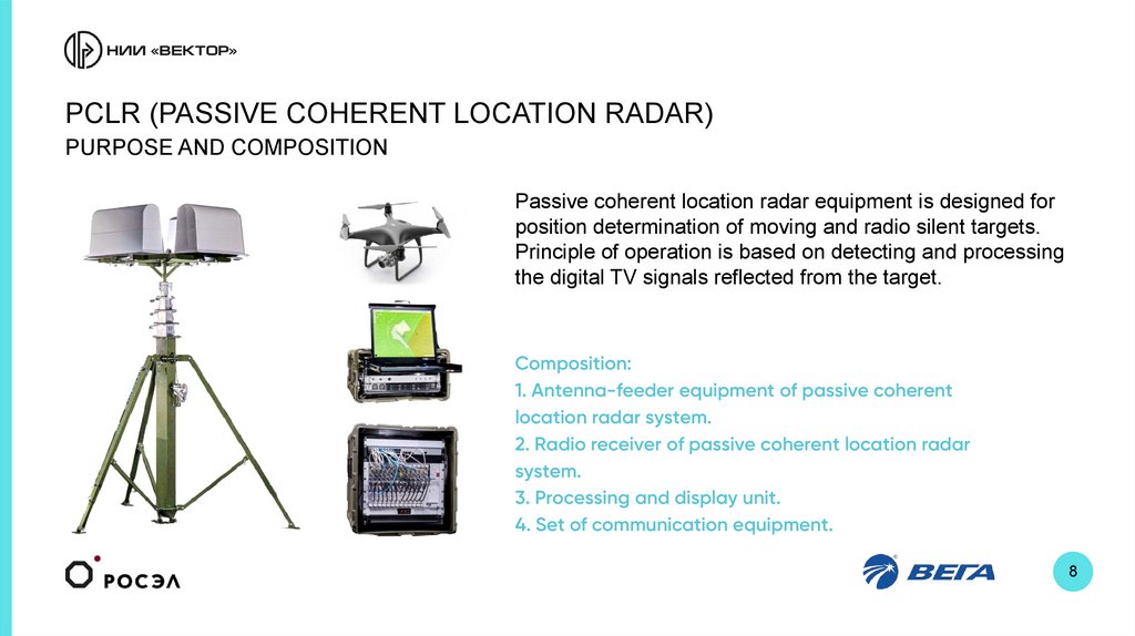
PCLR (PASSIVE COHERENT LOCATION RADAR)PURPOSE AND COMPOSITION
Passive coherent location radar equipment is designed for
position determination of moving and radio silent targets.
Principle of operation is based on detecting and processing
the digital TV signals reflected from the target.
Composition:
1. Antenna-feeder equipment of passive coherent
location radar system.
2. Radio receiver of passive coherent location radar
system.
3. Processing and display unit.
4. Set of communication equipment.
8
9.
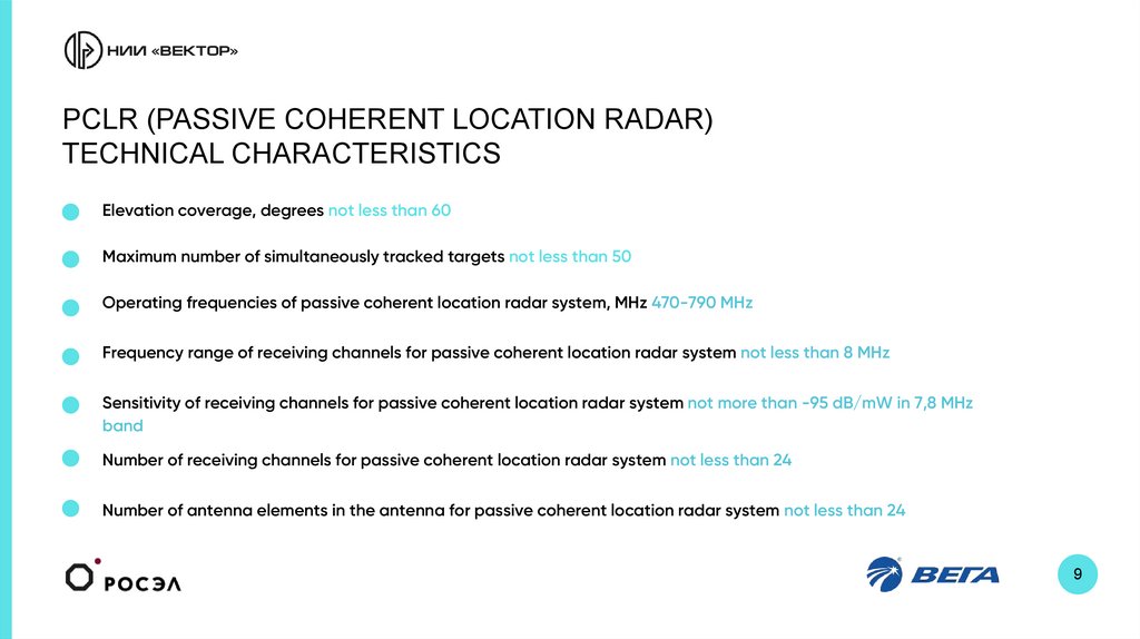
PCLR (PASSIVE COHERENT LOCATION RADAR)TECHNICAL CHARACTERISTICS
Elevation coverage, degrees not less than 60
Maximum number of simultaneously tracked targets not less than 50
Operating frequencies of passive coherent location radar system, MHz 470-790 MHz
Frequency range of receiving channels for passive coherent location radar system not less than 8 MHz
Sensitivity of receiving channels for passive coherent location radar system not more than -95 dB/mW in 7,8 MHz
band
Number of receiving channels for passive coherent location radar system not less than 24
Number of antenna elements in the antenna for passive coherent location radar system not less than 24
9
10.
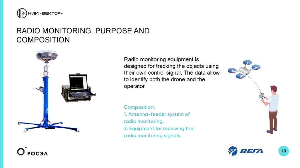
RADIO MONITORING. PURPOSE ANDCOMPOSITION
Radio monitoring equipment is
designed for tracking the objects using
their own control signal. The data allow
to identify both the drone and the
operator.
Composition:
1. Antenna-feeder system of
radio monitoring.
2. Equipment for receiving the
radio monitoring signals.
10
11.
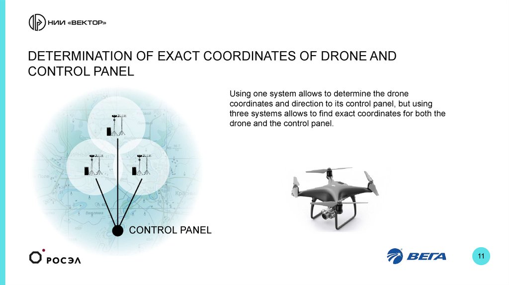
DETERMINATION OF EXACT COORDINATES OF DRONE ANDCONTROL PANEL
Using one system allows to determine the drone
coordinates and direction to its control panel, but using
three systems allows to find exact coordinates for both the
drone and the control panel.
CONTROL PANEL
11
12.
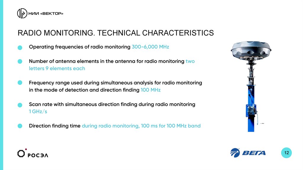
RADIO MONITORING. TECHNICAL CHARACTERISTICSOperating frequencies of radio monitoring 300-6,000 MHz
Number of antenna elements in the antenna for radio monitoring two
letters 9 elements each
Frequency range used during simultaneous analysis for radio monitoring
in the mode of detection and direction finding 100 MHz
Scan rate with simultaneous direction finding during radio monitoring
1 GHz/s
Direction finding time during radio monitoring, 100 ms for 100 MHz band
12
13.
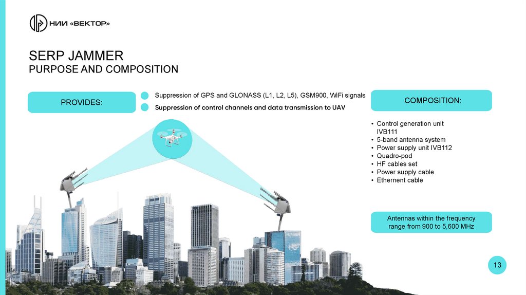
SERP JAMMERPURPOSE AND COMPOSITION
Suppression of GPS and GLONASS (L1, L2, L5), GSM900, WiFi signals
PROVIDES:
Suppression of control channels and data transmission to UAV
COMPOSITION:
• Control generation unit
IVB111
• 5-band antenna system
• Power supply unit IVB112
• Quadro-pod
• HF cables set
• Power supply cable
• Ethernent cable
Antennas within the frequency
range from 900 to 5,600 MHz
13
14.
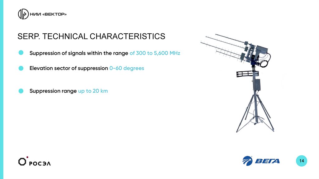
SERP. TECHNICAL CHARACTERISTICSSuppression of signals within the range of 300 to 5,600 MHz
Elevation sector of suppression 0-60 degrees
Suppression range up to 20 km
14
15.
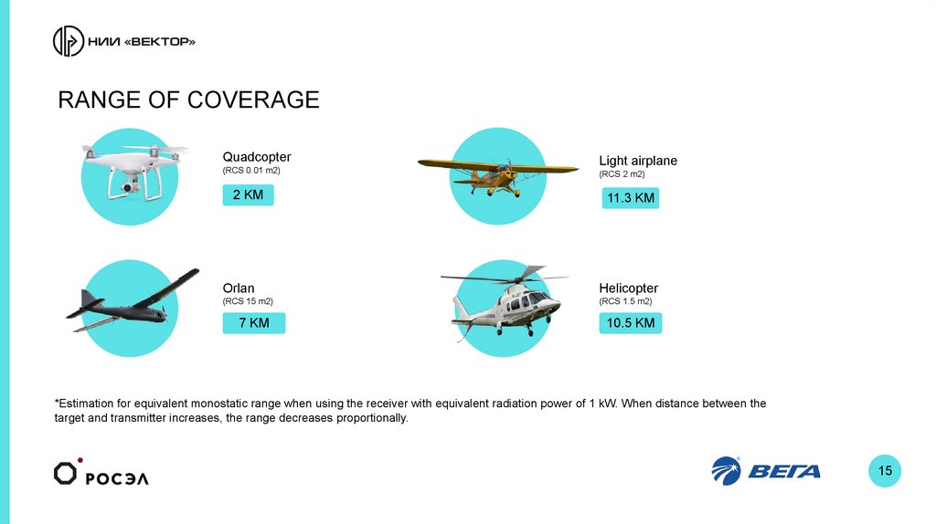
RANGE OF COVERAGEQuadcopter
(RCS 0.01 m2)
2 KM
Light airplane
(RCS 2 m2)
11.3 KM
Orlan
Helicopter
(RCS 15 m2)
(RCS 1.5 m2)
7 KM
10.5 KM
*Estimation for equivalent monostatic range when using the receiver with equivalent radiation power of 1 kW. When distance between the
target and transmitter increases, the range decreases proportionally.
15
16.
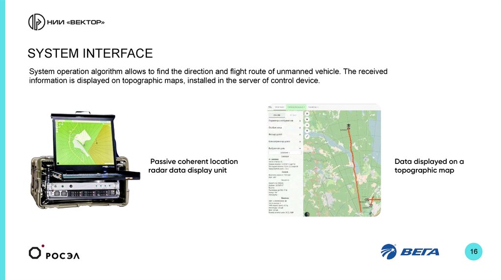
SYSTEM INTERFACESystem operation algorithm allows to find the direction and flight route of unmanned vehicle. The received
information is displayed on topographic maps, installed in the server of control device.
Passive coherent location
radar data display unit
Data displayed on a
topographic map
16
17.
BUILDING UP THE MULTIPOSITION COMPLEX OF PASSIVECOHERENT LOCATION RADAR AND RADIO MONITORING EQUIPMENT
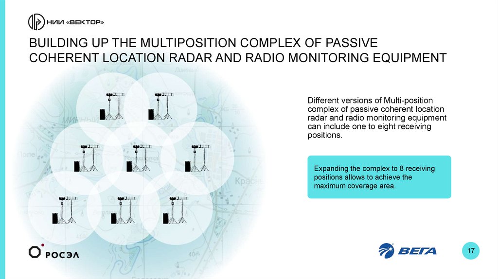
Different versions of Multi-position
complex of passive coherent location
radar and radio monitoring equipment
can include one to eight receiving
positions.
Expanding the complex to 8 receiving
positions allows to achieve the
maximum coverage area.
17
18.
18Scientific Research Institute “Vektor” JSC
14а ul. Akademika Pavlova, Saint
Petersburg, 197376
tel.: +7 (812) 295-10-97
+7 (812) 295-87-62
Fax: +7 (812) 591-72-74
E-mail: nii@nii-vektor.ru
Scientific Research
Institute “Vektor”