


 Электроника
Похожие презентации:


")

Microwave Group (MWG) & Compressor Dehydrator
1.
TRAINING COURSEMicrowave Group (MWG)
& Compressor Dehydrator
Primary Surveillance Radar Systems
Nº doc.: 0066605020000MA08
Edition: A Revision: 1
Date: 09/03/2020
2.
Warning of ConfidentialityThe data and information, in its totality or partial expression, contained in this document are property of
Indra Sistemas, S.A. This data and information cannot be disclosed totally or partially to third parties.
The copy, reproduction, public communication, dissemination, total or partial distribution, modification or
assignment will require the prior written authorization of Indra Sistemas, S.A. Its content cannot be used
for different purposes to those for which it is provided, its use being limited to the execution of the
Program it is supplied for.
0066605020000MA08
09/03/2020
2 de 632
3.
Signature SheetINDRA
Name
Signature
Date
Responsibility
Prepared
Jaime Herrero Gutiérrez
Systems Engineer
Revised
Carolina Rincón Gila
Systems Engineer
Approved
Crisanto Molina Blesa
Systems Engineer
Authorized
Crisanto Molina Blesa
Systems Engineer
0066605020000MA08
09/03/2020
3 de 633
4.
Changes RecordDOCUMENT CHANGES RECORD
EDITION
REVISION
DATE
CHAPTER
REASON OF THE
CHANGES
A
0
18/04/2017
All
Content Review
A
1
09/03/2020
All
Updates
0066605020000MA08
09/03/2020
4 de 634
5.
AcronymsAPG
Att
BITE
cm
CMS
CRCH
DC
dB
dBc
dBm
FLU
FWD
GHz
GRPG
h
HB
Hz
Kg
kPa
kW
LB
Antenna and Pedestal Group
Attenuation
Built-in test Equipment
centimeter
Control and Monitor System
Coaxial Receiver Channel
Directional Coupler
Decibel
Decibel (relative to carrier)
Decibel (relative to milliwatt)
Filter and LNA Unit
Forward
GigaHertz
Generator, Receiver and Processor Group
Hour
Hi Beam
Hertz
Kilogram
KiloPascal
Kilowatt
Low Beam
0066605020000MA08
09/03/2020
5 de 635
6.
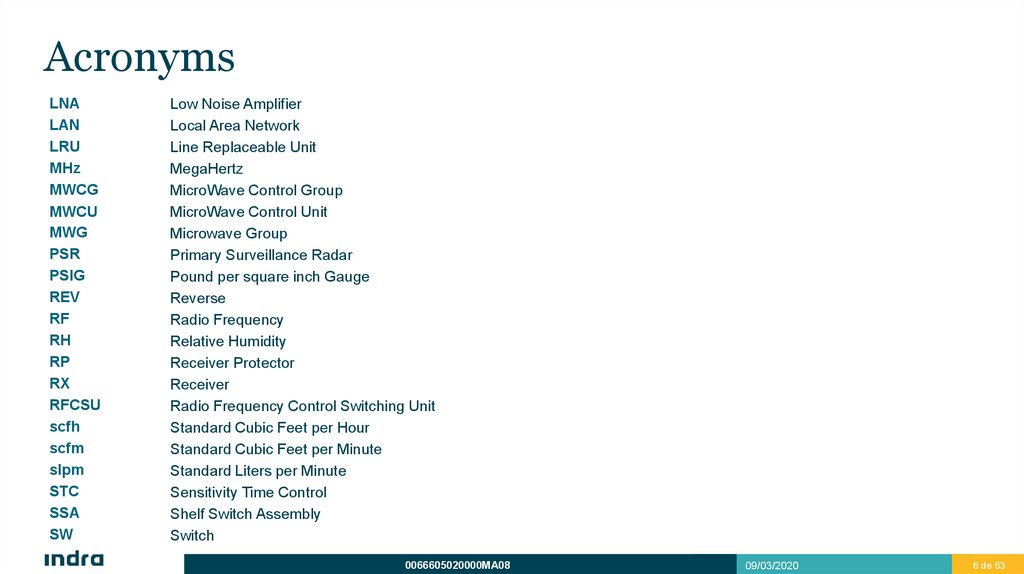
AcronymsLNA
LAN
LRU
MHz
MWCG
MWCU
MWG
PSR
PSIG
REV
RF
RH
RP
RX
RFCSU
scfh
scfm
slpm
STC
SSA
SW
Low Noise Amplifier
Local Area Network
Line Replaceable Unit
MegaHertz
MicroWave Control Group
MicroWave Control Unit
Microwave Group
Primary Surveillance Radar
Pound per square inch Gauge
Reverse
Radio Frequency
Relative Humidity
Receiver Protector
Receiver
Radio Frequency Control Switching Unit
Standard Cubic Feet per Hour
Standard Cubic Feet per Minute
Standard Liters per Minute
Sensitivity Time Control
Shelf Switch Assembly
Switch
0066605020000MA08
09/03/2020
6 de 636
7.
AcronymsTGT
Target
TX
Transmission
TXG
Transmitter Group
VSWR
Video Standing Wave Ratio
w
watt
WCD
Waveguide Compressor Dehydrator
WGD
Waveguide Duplexer
WGS
Waveguide Switch
WPD
Waveguide Power Load
WRP
Waveguide Receiver Protector
WX
Weather
µs
microsecond
0066605020000MA08
09/03/2020
7 de 637
8.
IndexMicrowave Group Overview
1
Physical Description
2
Channel Distribution
Transmission Channel
Reception Channel
Test Signals Distribution
Summary
MWG Functional Description
Signal Transmission and Reception
STC
Test Signal Distribution (SSA, Switches and
Couplers)
Redundancy
3
9.
IndexLRU List and Interfaces
4
Compressor Dehydrator
5
Main Features
Physical Description
Functional Description
Operation
Interface
10.
Microwave GroupOverview
1
11.
Microwave Group OverviewMicrowave Group Overview
The Microwave Group (MWG) directs transmitted signal from the Transmitter Group (TXG) to the Antenna Pedestal Group.
MWG routes the received signals from the APG to the Generator, Receiver and Processor Group (GRPG).
0066605020000MA08
09/03/2020
11 de 63
11
12.
Microwave Group OverviewMicrowave Group Overview
SHELF SWITCH ASSEMBLY
(SSA)
HARMONIC
FILTER
BIDIRECTIONAL
COUPLER
WAVEGUIDE POWER
LOAD (WPD)
WAVEGUIDE
DUPLEXER (WGD)
BIDIRECTIONAL
COUPLER
CRCH
CRCH
COAXIAL SWITCH
COAXIAL RECEIVER CHANNEL (CRCH)
WAVEGUIDE SWITCH (WGS)
WAVEGUIDE RECEIVER PROTECTOR (WRP)
FILTER AND LNA UNIT (FLU)
0066605020000MA08
09/03/2020
12 de 63
12
13.
Physical Description• Channel Distribution
• Transmission Channel
• Reception Channel
• Test Signals Distribution
• Summary
2
14.
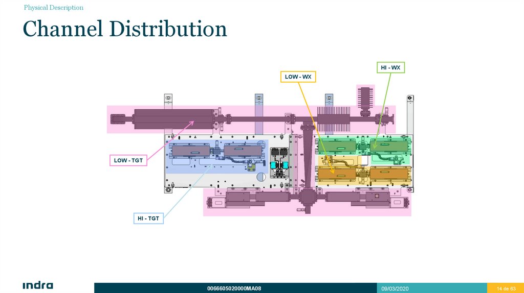
Physical DescriptionChannel Distribution
HI - WX
LOW - WX
LOW - TGT
HI - TGT
0066605020000MA08
09/03/2020
14 de 63
14
15.
Physical DescriptionTransmission Channel
Harmonic Filter
Couplers
Power load
Duplexer
0066605020000MA08
09/03/2020
15 de 63
15
16.
Physical DescriptionTransmission Channel
Harmonic Filter
Peak Power: up to 25kW from 2.7GHz to 2.9GHz with a maximum duty cycle of 11%.
Insertion Loss: 0.15dB max.
VSWR: 1.10:1 for working band / 1.50:1 for harmonics.
Harmonics:
Att. 40dB at 5.4 - 5.8GHz
Att. 30dB at 8.1 - 8.7GHz
Att. 10dB at 10.8 - 11.6GHz
0066605020000MA08
09/03/2020
16 de 63
16
17.
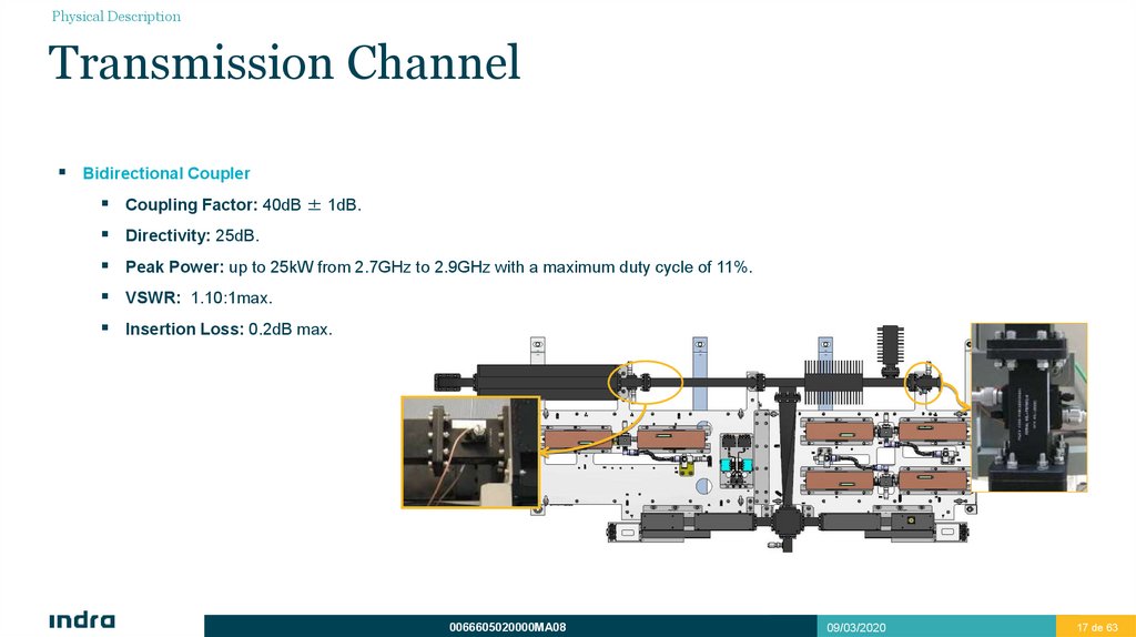
Physical DescriptionTransmission Channel
Bidirectional Coupler
Coupling Factor: 40dB ± 1dB.
Directivity: 25dB.
Peak Power: up to 25kW from 2.7GHz to 2.9GHz with a maximum duty cycle of 11%.
VSWR: 1.10:1max.
Insertion Loss: 0.2dB max.
0066605020000MA08
09/03/2020
17 de 63
17
18.
Physical DescriptionTransmission Channel
Duplexer
Transmitter
Port 1:Input from TX
Port 1
Port 2: Output to APG. Input Channel LOW-TGT.
Port 4
Port 3: Output to Receiver
Power Load
Port 2
Antenna
Port 3
Receiver
Port 4: Power Load
The transmitted signal fom TXG comes through port 1, and we can see in the diagram, that the direction of rotation of duplexer is clockwise so the signal goes
to the antenna through port 2. In Reception, the input is the port2 and the signal goes to port 3 to the receptor. The port4 is the Power Load and is to aviod an
incoming high signal.
Peak Power: up to 25kW from 2.7GHz to 2.9GHz with a maximum duty cycle of 11%.
Insertion Loss: 0.5dB max.
Isolation: 25dB min
0066605020000MA08
09/03/2020
18 de 63
18
19.
Physical DescriptionReception Channel
Reception Channel LOW-TGT
Reception Channel Input HI-TGT
Reception Channel Input
LOW/HI-WX
RF INPUT
FROM TXG
RF OUTPUTS
TO GRPG
0066605020000MA08
09/03/2020
19 de 63
19
20.
Physical DescriptionReception Channel
Reception Channel HI-TGT
Reception Channels HI-Wx and LO-Wx
Only for reception
Only for reception
Allows test signal injection to check status
Allow test signal injection to check status
RF Output to
Receiver
Receiver 1
RF Signal
Input
RF Output to
Receiver
Receiver 2
RF Output to
Receiver
Receiver 1
RF Output to
Receiver
Receiver 2
RF Signal
Input
0066605020000MA08
09/03/2020
20 de 63
20
21.
Physical DescriptionReception Channel
Summary
Target Low Beam
Coupler (x2)
Lightning Protector
Duplexer
Coupler
Waveguide Switch
Coaxial Switch
Waveguide RP+STC (x2)
Weather Low Beam / Weather High Beam
Filter (x2)
LNA (x2)
Coaxial Receiver Channel (x2)
Target High Beam
Lightning Protector
Coupler
Coaxial Switch
Coaxial Receiver Channel (x2)
0066605020000MA08
09/03/2020
21 de 63
21
22.
Physical DescriptionReception Channel
Target Low Beam
Waveguide Switch
Insertion Loss: 0.10dB max.
VSWR: 1.15:1
Isolation: 65dB min.
0066605020000MA08
09/03/2020
22 de 63
22
23.
Physical DescriptionReception Channel
Target Low Beam
RP+STP Waveguide
Peak Power: up to 25kW from 2.7GHz to 2.9GHz with a maximum
duty cycle of 11%.
Insertion Loss: 0.7dB max.
VSWR: 1.4:1
0066605020000MA08
09/03/2020
23 de 63
23
24.
Physical DescriptionReception Channel
Target Low Beam
RECEIVER PROTECTOR
When the system is transmitting the unit receives power in the input
RF connector due to unwanted couplings and reflected power from
the antenna. The unit’s receiver protector has to protect the
elements after itself against high power leakages, so during system
transmission pulses the unit’s receiver protector has to present a
high isolation 25kW from 2.9GHz
0066605020000MA08
09/03/2020
24 de 63
24
25.
Physical DescriptionReception Channel
Target Low Beam
Typical Input Signal
RP+STP Waveguide
90 us
Max Power outside RP
4 us
1.2 us
2000 W
Attenuator parameters programmable
Att. Range: 0 - 40dB
0W
Step: ~0.16dB (8bits)
Frequency Step: 2.6MHz
Time from Max Att to Insertion Loss: 10µs max
Maximum Output Signal
Time from Insertion Loss to Max Att: 5µs max
Spike Pulse
max peak power
Spike Pulse
2 nanoJoules max
Flat leakage
max peak power
20 dBm
Spike Leakage Power: maximum power at the output when protection state is starting.
16 dBm
Flat Leakage Power: maximum power at the output when protection state is stationary
activated.
0 Watt
Spike pulse energy: maximum amount of energy transmitted to the receiver protector output
exceeding the flat leakage power
0066605020000MA08
09/03/2020
25 de 63
25
26.
Physical DescriptionReception Channel
Target Low Beam
Filter
Insertion Loss in band pass: 0.3dB max
VSWR: 1.5:1 max in band pass
Rejection capabilities:
DC - 2.5GHz: 40dBc min
2.6GHz:
10dBc min
3 GHz:
10dBc min
3.1 - 6GHz: 40dBc min
0.3 dB
Insertion loss
10 dB
40 dB
2500
2600
2700
2900 3000
Frequency (MHz)
3100
6000
0066605020000MA08
09/03/2020
26 de 63
26
27.
Physical DescriptionReception Channel
Target Low Beam
LTE 4G Filter
Gain: 40dB min (T=23 ºC).
Gain flatness: ±0.5dB max.
VSWR: 1.5:1 max.
Noise Figure: 0.4dB typical (T=23 ºC).
1dB Compression Point: 13dBm min.
LTE 4G Filter provides protection for our system.
Keep clean the S-Band frequencies from
interferences coming from LTE Base Stations.
The design assures at least 20dB of rejection at
the input of the LNA for LTE Band-41 Frequencies
0066605020000MA08
09/03/2020
27 de 63
27
28.
Physical DescriptionReception Channel
Target High Beam
Lightning Protector - Quarter Wave Type.
Added to the system to protect it from electromagnetic weather dischargers. There is one Lightning Protector on each coaxial channel input.
Quarter-wave lightning protectors are basically maintenance-free. However, we recommend customers to check the condition of the grounding/bonding
system connections and of the connector interfaces in the context of routine system maintenance. But connector interfaces which are heavily damaged
by lightning current overload (in excess of specification) will lead to increased reflections and will be detected by the return loss tracing circuit of the
transmitter anyway. Field experience shows that lightning protectors are not the only components which can be affected in such cases of direct hits
0066605020000MA08
09/03/2020
28 de 63
28
29.
Physical DescriptionReception Channel
Target High Beam
Coaxial Coupler
VSWR: 1.15:1 max
Insertion Loss: 0.2dB max
Coupling Factor: 30dB
Directivity: 27dB
0066605020000MA08
09/03/2020
29 de 63
29
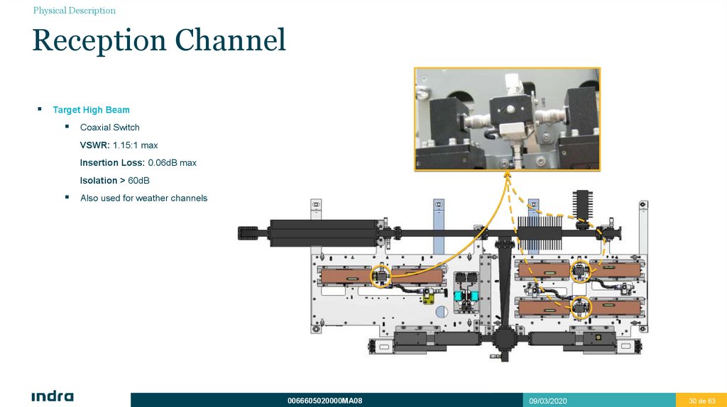
30.
Physical DescriptionReception Channel
Target High Beam
Coaxial Switch
VSWR: 1.15:1 max
Insertion Loss: 0.06dB max
Isolation > 60dB
Also used for weather channels
0066605020000MA08
09/03/2020
30 de 63
30
31.
Physical DescriptionReception Channel
Target High Beam
Coaxial Receiver Channel
VSWR: 1.5:1 max
Noise figure: 2.0 dB typ.
Gain: 26dB min
Attenuation Range: 0 to 31.5 dB
CRCHs also used for weather channels
Unit Gain
26 dB min
over passband
6 dB
Receiver
Protector
-24 dB
DC 2500
2600
2700
2900
3000 3100
6000
Frequency (MHz)
Band pass
filter
Low Noise
Amplifier 1st
Digital
attenuator
Input
Low Noise
Amplifier 2nd
Output
Output
Power and Control
0066605020000MA08
09/03/2020
31 de 63
31
32.
Physical DescriptionReception Channel
Weather Low Beam and High Beam
Lightning Protector (Described before).
Coaxial Coupler (Described before).
Coaxial Switch (Described before).
HI - WX
LOW - WX
Coaxial Receiver Channel (Described before).
0066605020000MA08
09/03/2020
32 de 63
32
33.
Physical DescriptionTest Signals Distribution
SSA
Switches (x2)
Splitter 1:4 (x2)
Splitter 1:2 (x2)
Attenuators.
0066605020000MA08
09/03/2020
33 de 63
33
34.
Physical DescriptionTest Signals Distribution
SSA
Switches
Route test signals from EPG A and EPG B to dividers.
TEST SIGNAL
INJECTION TO
ACTIVE CHANNEL
TEST SIGNAL FGG 1
HI -TGT
LOW -TGT
HI-WX
LOW-WX
ATT
TEST SIGNAL FGG 2
0066605020000MA08
HI -TGT
LOW -TGT
HI-WX
LOW-WX
TEST SIGNAL
INJECTION TO
STANBY
CHANNEL
09/03/2020
34 de 63
34
35.
Physical DescriptionTest Signals Distribution
SSA
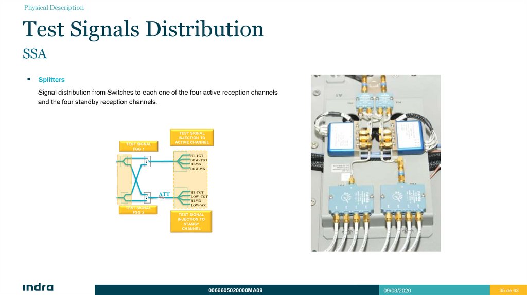
Splitters
Signal distribution from Switches to each one of the four active reception channels
and the four standby reception channels.
TEST SIGNAL
INJECTION TO
ACTIVE CHANNEL
TEST SIGNAL
FGG 1
HI -TGT
LOW -TGT
HI-WX
LOW-WX
ATT
TEST SIGNAL
FGG 2
HI -TGT
LOW -TGT
HI-WX
LOW-WX
TEST SIGNAL
INJECTION TO
STANBY
CHANNEL
0066605020000MA08
09/03/2020
35 de 63
35
36.
Physical DescriptionTest Signals Distribution
SSA
Attenuator
30dB Att. to adapt signal in the way of the four standby channels.
TEST SIGNAL
INJECTION TO
ACTIVE CHANNEL
TEST SIGNAL
FGG 1
HI -TGT
LOW -TGT
HI-WX
LOW-WX
ATT
TEST SIGNAL
FGG 2
HI -TGT
LOW -TGT
HI-WX
LOW-WX
TEST SIGNAL
INJECTION TO
STANBY
CHANNEL
0066605020000MA08
09/03/2020
36 de 63
36
37.
Physical DescriptionSummary
Directional
Coupler
(Antenna Rev
Power)
Directional Coupler
(Tx Rev Power)
(Tx Fw Power)
From
TXG
Shelf switch Assembly
(Test signals distribution)
HI WX and
LO WX
CHANNELS
Power Load
Harmonic Filter
Duplexer
From/To
APG
Coax. Switch
(x3)
HI TGT
CHANNEL
Lightning Protector (x3)
Coupler (x3)
LO TGT CHANNEL
WG Receiver Protector + STC
(x2)
S Band filter
(x2)
Waveguide Switch
LNA (x2)
Coaxial
Receiver
Channel (x6)
0066605020000MA08
09/03/2020
37 de 63
37
38.
MWG FunctionalDescription
• Signal Transmission and Reception
• STC
• Test Signal Distribution (SSA, Switches and Couplers)
• Redundancy
3
39.
MWG Functional DescriptionSignal Transmission and Reception
0066605020000MA08
09/03/2020
39 de 63
39
40.
MWG Functional DescriptionSignal Transmission and Reception
Signal Transmission and Reception
MWG routes signal previously amplified by TXG to the Antenna, going through Harmonic Filter and Duplexer. At some points, samples of forward and
reverse signals from/to Antenna are extracted by using bidirectional couplers.
Duplexer allows transmission and reception along low beam channel, isolating not less than 25dB in each way.
In every reception path, a switch, controlled by MWCG (in GRPG), routes the signal to the active channel.
Signal travels through a RP and a programmable attenuator (STC). Then it passes through a band-pass filter and a LNA.
STCs are controlled from MWCG (in GRPG).
Signal received from each of the four channels is routed to GRPG: LOW-TGT, HI-TGT, LOW-WX and HI-WX.
0066605020000MA08
09/03/2020
40 de 63
40
41.
MWG Functional DescriptionSignal Transmission and Reception
Tx REV power
ANT REV power
LOW-TGT
COAX
Harmonic Filter
Directional Coupler
TO ANTENNA
LOW BEAM TGT
COAX
Directional Coupler
Duplexer
TRANSMITTER
TEST SIGNAL INJECTION
Tx FWD power
Switch
LNA
Band Pass Filter
Receiver Protector
+ STC
COAX
COAX
Receiver Protector
+ STC
Band Pass Filter
TO RECEIVER 1
LNA
TO RECEIVER 2
COAX
TEST SIGNAL INJECTION
HI-TGT
COAX
COAX
TO ANTENNA
HIGH BEAM TGT
Directional Coupler
TEST SIGNAL INJECTION
CRCH
CRCH
Switch
COAX
LNA
Band Pass Filter
STC
Receiver
Protector
COAX
Receiver
Protector
STC
Band Pass Filter
LNA
TO RECEIVER 2
TO RECEIVER 1
TEST SIGNAL INJECTION
0066605020000MA08
09/03/2020
41 de 63
41
42.
MWG Functional DescriptionSignal Transmission and Reception
LOW-WX
FROM ANTENNA
COAX
COAX
LOW BEAM WX
Directional Coupler
TEST SIGNAL INJECTION
Switch
LNA
Band Pass Filter
STC
COAX
Receiver Protector
Receiver Protector
CRCH
STC
Band Pass Filter
LNA
CRCH
TO RECEIVER 2
TO RECEIVER 1
COAX
TEST SIGNAL INJECTION
HI-WX
FROM ANTENNA
COAX
COAX
HI BEAM WX
Directional Coupler
TEST SIGNAL INJECTION
Switch
LNA
Band Pass Filter
STC
COAX
Receiver Protector
CRCH
Receiver Protector
STC
CRCH
TO RECEIVER 1
Band Pass Filter
LNA
TO RECEIVER 2
TEST SIGNAL INJECTION
0066605020000MA08
09/03/2020
42 de 63
42
43.
MWG Functional DescriptionSTC
STC (Sensitivity Time Control)
Programmable Attenuators are used to control STC.
STCs are controlled by MWCU units in MWCG (GRPG).
Each STC allows the following attenuation:
STC (CRCH): up to 32dB by 0.5 dB steps (6 bits).
RP+STC (LOW-TGT): up to 40 dB by 0.16 dB steps (8 bits).
0066605020000MA08
09/03/2020
43 de 63
43
44.
MWG Functional DescriptionTest Signal Distribution (SSA, Switches and
Couplers)
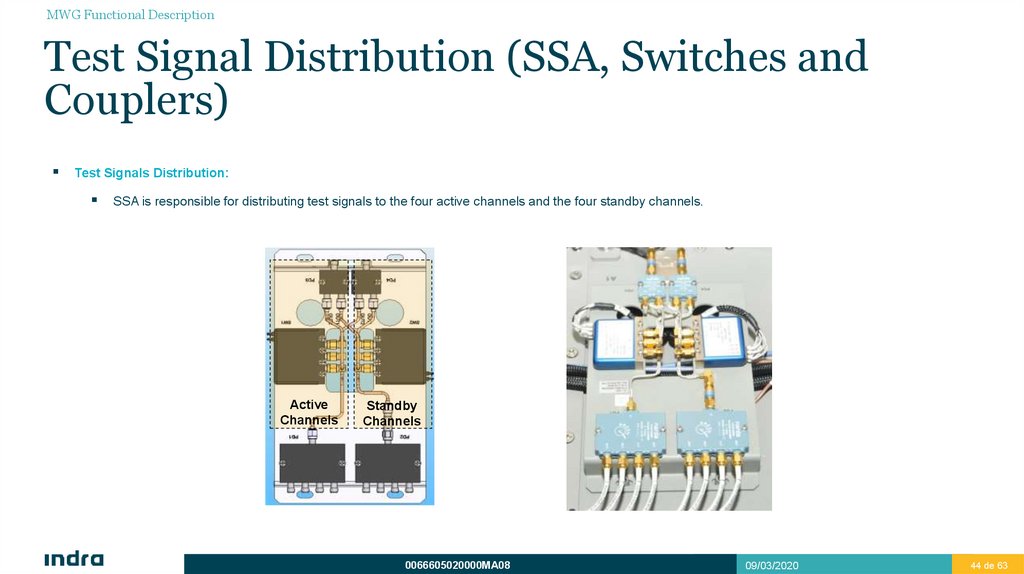
Test Signals Distribution:
SSA is responsible for distributing test signals to the four active channels and the four standby channels.
Active
Channels
Standby
Channels
0066605020000MA08
09/03/2020
44 de 63
44
45.
MWG Functional DescriptionTest Signal Distribution (SSA, Switches and
Couplers)
Test Signals Distribution:
Switch: Routes the signal that comes from the Antenna to the Active Channel and test signal to Standby Channel.
Coupler: The coupled port is used to inject the Test Signal to the Active Channel.
0066605020000MA08
09/03/2020
45 de 63
45
46.
MWG Functional DescriptionRedundancy
Redundancy
Non redundant elements
Harmonic Filter
Duplexer
Power Load
Waveguide Switch
Coaxial Switch (x3)
SSA
From Switches, all the elements are redundant
Receiver Protector + STC (TGT LB)
Band-pass Filter (TGT LB)
LNA (TGT LB)
Coaxial Receiver Channel (WX LB and HB, TGT HB)
0066605020000MA08
09/03/2020
46 de 63
46
47.
LRU List andInterfaces
4
48.
LRU List and InterfacesLRU List and Interfaces
LRUs List
Harmonic Filter.
Bidirectional Coupler (x2).
Directional Coupler (x3).
Duplexer
Power Load
Waveguide Switch
Coaxial Switch
Waveguide Receiver Protector (RP + STC) (x2).
FLU (Filter and LNA Unit) (x2).
SSA
Coaxial Receiver Channel (x6)
0066605020000MA08
09/03/2020
48 de 63
48
49.
J4J8
J7
TXG
0066605020000MA08
J42
J43
J44
J45
J46
J47
J48
J49
J35
TST MWG EPG2
W3023
TST MWG EPG1
W3022
LNA OUT HI-WX CH2
W3021
LNA OUT HI-WX CH1
W3020
LNA OUT LO-WX CH2
W3019
LNA OUT LO-WX CH1
W3018
LNA OUT HI-TGT CH2
W3017
LNA OUT HI-TGT CH1
W3016
LNA OUT LO-TGT CH2
J3
W3015
J4
LNA OUT LO-TGT CH1
J2
W3014
WG
W3026 ANT REV PWR
ROTARY
JOINT
W3025 TX REV PWR
W3024 TX FWD PWR
LRU List and Interfaces
LRU List and Interfaces
External Interfaces: Coaxial
W3001 LO TGT
W3002 HI TGT
W3003 LOW WX
W3004 HI WX
MWG
J36
GRPG
09/03/2020
49 de 63
49
50.
W2043 HI-TGT SW C/SW2044 LO-WX SW C/S
W2045 HI-WX SW C/S
W2046 MWG LO-TGT CH1 C/S
W2047 MWG LO-TGT CH2 C/S
J37
J38
J39
J40
J41
J27
J28
0066605020000MA08
J29
W2052 MWG HI-WX CH1 C/S
J31
J32
J33
W2053 MWG HI-WX CH2 C/S
W2051 MWG LO-WX CH2 C/S
J30
W2050 MWG LO-WX CH1 C/S
W2049 MWG HI-TGT CH2 C/S
W2048 MWG HI-TGT CH1 C/S
W2042 LO-TGT SW C/S
W2041 SSA C/S
LRU List and Interfaces
LRU List and Interfaces
External Interfaces: Digital
MWG
J34
GRPG
09/03/2020
50 de 63
50
51.
LRU List and InterfacesLRU List and Interfaces
Internal MWG interfaces
0066605020000MA08
09/03/2020
51 de 63
51
52.
CompressorDehydrator
• Main Features
• Physical Description
• Functional Description
• Operation
• Interface
5
53.
Compressor DehydratorCompressor Dehydrator
0066605020000MA08
09/03/2020
53 de 63
53
54.
Compressor DehydratorMain Features
COMPRESSOR FEATURES
Controlled Output Pressure
2 to 6 PSIG
Output Capacity
7.2 SCFH (204 l/h) or 0.12 SCFM (3.4 l/min)
Output Dew Point
-50ºF (-45ºC)
Electrical Input
115/230 ±10% VAC, 50/60 Hz
Low Pressure Alarm
<1 PSIG
High Humidity Alarm
> 7.5% RH, factory set.
Excess Run Alarm Set Point
10 min, factory set.
Power Fail Alarm
Loss of input power
Net weight
16.1 kg
Monitoring and BITE alarms
Monitoring in CMS
External pressure regulator
0 to 2 PSIG
Output connector
3/8” polytube, compression
0066605020000MA08
09/03/2020
54 de 63
54
55.
Compressor DehydratorPhysical Description
The dehydrator provides dry air for pressurizing waveguide line at 1.5 PSIG to prevent degradation.
It shall be connected directly to waveguide with a transition.
The dehydrator consists of: Harmonic Filter.
An electrically driven air compressor.
A membrane dryer assembly.
A automatic pressure sensing system.
Alarm outputs housed in a rigid metal chassis.
An external pressure regulator.
The front panel features a control interface with display for alarms and pressure.
1PSIG 1lb / in 2 14,22kg / cm2 6894.75Pa
1.5PSIG 21,3kg / cm2 10kPa
0066605020000MA08
09/03/2020
55 de 63
55
56.
Compressor DehydratorPhysical Description
DISPLAY
MEMBRANE
PRESSURE
REGULATOR
0.1u/1u
FILTERS
EXTERNAL VIEW
RESERVOIR
TANK
COMPRESSOR
INTAKE
FILTER
INTERNAL VIEW
0066605020000MA08
09/03/2020
56 de 63
56
57.
Compressor DehydratorPhysical Description
Low Pressure
Excess
Run
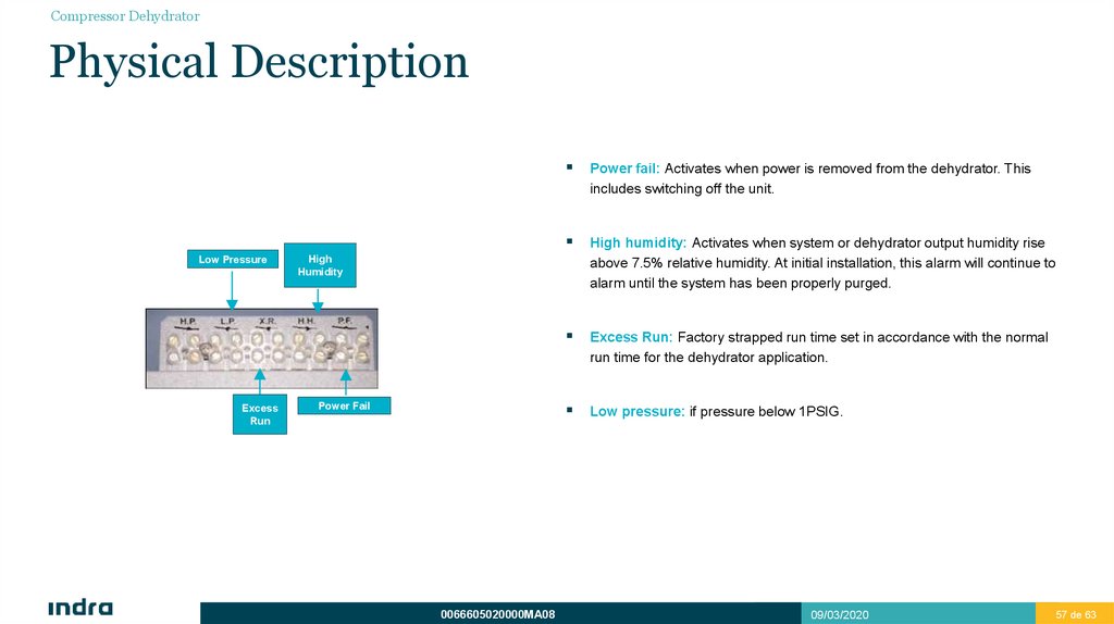
Power fail: Activates when power is removed from the dehydrator. This
includes switching off the unit.
High humidity: Activates when system or dehydrator output humidity rise
above 7.5% relative humidity. At initial installation, this alarm will continue to
alarm until the system has been properly purged.
Excess Run: Factory strapped run time set in accordance with the normal
run time for the dehydrator application.
Low pressure: if pressure below 1PSIG.
High
Humidity
Power Fail
0066605020000MA08
09/03/2020
57 de 63
57
58.
Compressor DehydratorFunctional Description
The compressor maintains transmission line pressures in a margin from 2 to 6 lb/in2.
It is intended for standard microwave antenna applications and any other transmission line pressurization requirement that supports a medium pressure limit.
An external regulator is used to maintain a constant pressure of 1.5 PSIG.
0066605020000MA08
09/03/2020
58 de 63
58
59.
Compressor DehydratorFunctional Description
In order to provide a constant supply of dry air to small air volume systems, and to
maintain an acceptable dryness level in the product air stream, a high-pressure
reservoir tank is utilized.
0066605020000MA08
This reservoir tank is connected to a pressure regulator and orifice to yield
a regulated output pressure of 3.0 psig and a nominal flow rate of 3.4
SLPM.
In addition to supplying the output air, the reservoir tank also provides the
dry air for the feedback loop. The feedback loop is necessary to maintain
the dryness of the membrane cartridge.
09/03/2020
59 de 63
59
60.
Compressor DehydratorFunctional Description
During normal operation, the bleed air in the feedback loop will cause the pressure to slowly drop in the internal reservoir tank, and the MT050B compressor
will cycle automatically.
These cycles will take place regardless of the system volume or condition of the transmission line the dehydrator is connected to. The rate of these
cycles, however, will vary.
To air drying the dehydrator uses a membrane cartridge, before that, air goes through a double filter:
The first one filter 1μm and the second one filter 0.1μm
These filters stop pollution, dust or saline fog, and 99.99% of water.
Solenoid discharge excess water from filter bowls.
After filtering air goes through membrane cartridge:
The membrane consists of thousands of very thin tubes
Pressurized air goes through these tubes, and water particles can’t continue.
0066605020000MA08
09/03/2020
60 de 63
60
61.
Compressor DehydratorOperation
The display will reflect a pressure between 0 and 21 kPa (3.0 psig) while the output flow is between 0 and 3.4 SLPM (0.12 SCFM).
The pressure sensor tracks the pressure beyond the flow control orifice and will show the actual pressure before the external regulator. To check the real
transmission line pressure, check the value in the pressure regulator gauge.
During the initial pressurization of the transmission line, the dehydrator will cycle every 2 to 4 minutes with the system at 0 psig pressure.
As the dehydrator pressurizes the system, the cycle times will increase and the pressure will rise until the dehydrator output is balanced with the system leak,
at which point the cycle times will stabilize.
0066605020000MA08
09/03/2020
61 de 63
61
62.
Compressor DehydratorInterface
During the compressor installation, pressurization window at the Microwave Group output, is required.
The compressor output shall be connected to a special transition, installed in the MWG.
The alarm outputs are connected to GRPG. GRPG reports to CMS, the BITE of the whole system via LAN.
0066605020000MA08
09/03/2020
62 de 63
62