


 Электроника
Похожие презентации:


 & Compressor Dehydrator")


")
Operation and maintenance introduction to the mode-s
1.
OPERATION AND MAINTENANCEINTRODUCTION TO THE MODE-S
SYSTEM TRAINING COURSE
Indra PSR & Mode-S Systems
ATM
Nº doc.: 0204700000000MA
Edición: A Revisión: 0
Fecha: 01/09/2021
2.
Warning of ConfidentialityThe data and information, in its totality or partial expression, contained in this document are property of Indra
Sistemas, S.A. This data and information cannot be disclosed totally or partially to third parties. The copy,
reproduction, public communication, dissemination, total or partial distribution, modification or assignment will
require the prior written authorization of Indra Sistemas, S.A. Its content cannot be used for different purposes
to those for which it is provided, its use being limited to the execution of the Program it is supplied for.
0204700000000MA _A0
01/09/2021
2 de 22
3.
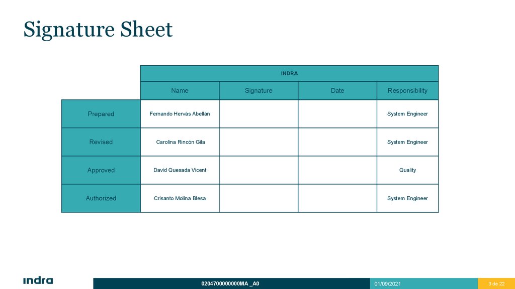
Signature SheetINDRA
Name
Signature
Date
Responsibility
Prepared
Fernando Hervás Abellán
System Engineer
Revised
Carolina Rincón Gila
System Engineer
Approved
David Quesada Vicent
Quality
Authorized
Crisanto Molina Blesa
System Engineer
0204700000000MA _A0
01/09/2021
3 de 22
4.
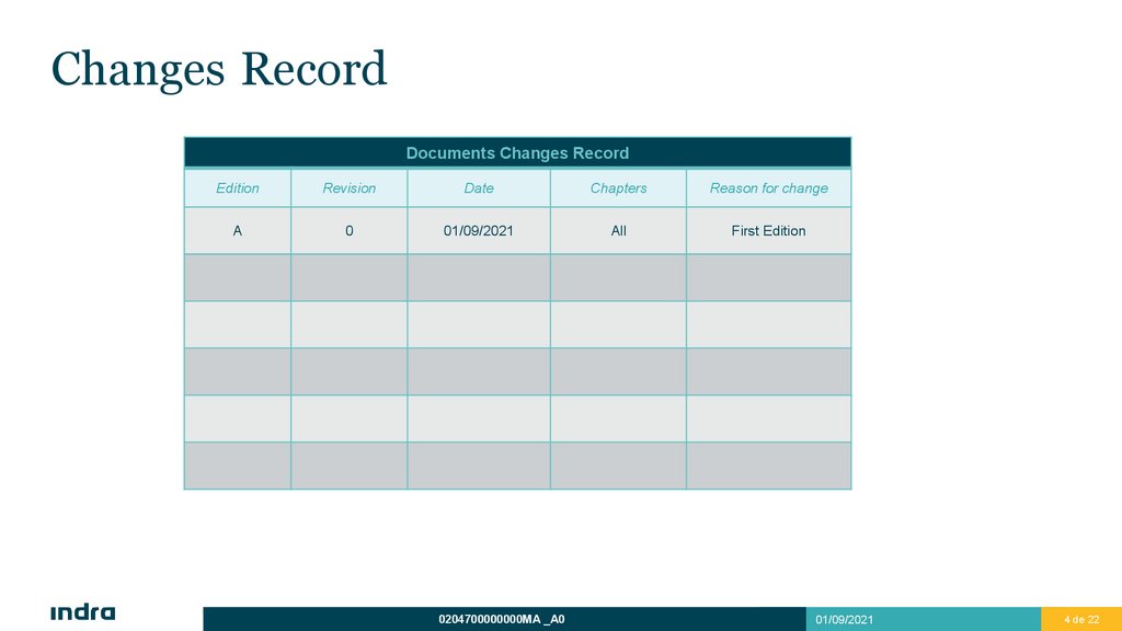
Changes RecordDocuments Changes Record
Edition
Revision
Date
Chapters
Reason for change
A
0
01/09/2021
All
First Edition
0204700000000MA _A0
01/09/2021
4 de 22
5.
Training CourseOverview
Logistic
Objectives
Daily Timetable
Content
Agenda
1
6.
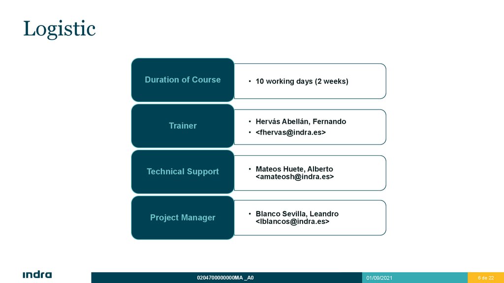
LogisticDuration of Course
• 10 working days (2 weeks)
Trainer
• Hervás Abellán, Fernando
• <fhervas@indra.es>
Technical Support
Project Manager
• Mateos Huete, Alberto
<amateosh@indra.es>
• Blanco Sevilla, Leandro
<lblancos@indra.es>
0204700000000MA _A0
01/09/2021
6 de 22
7.
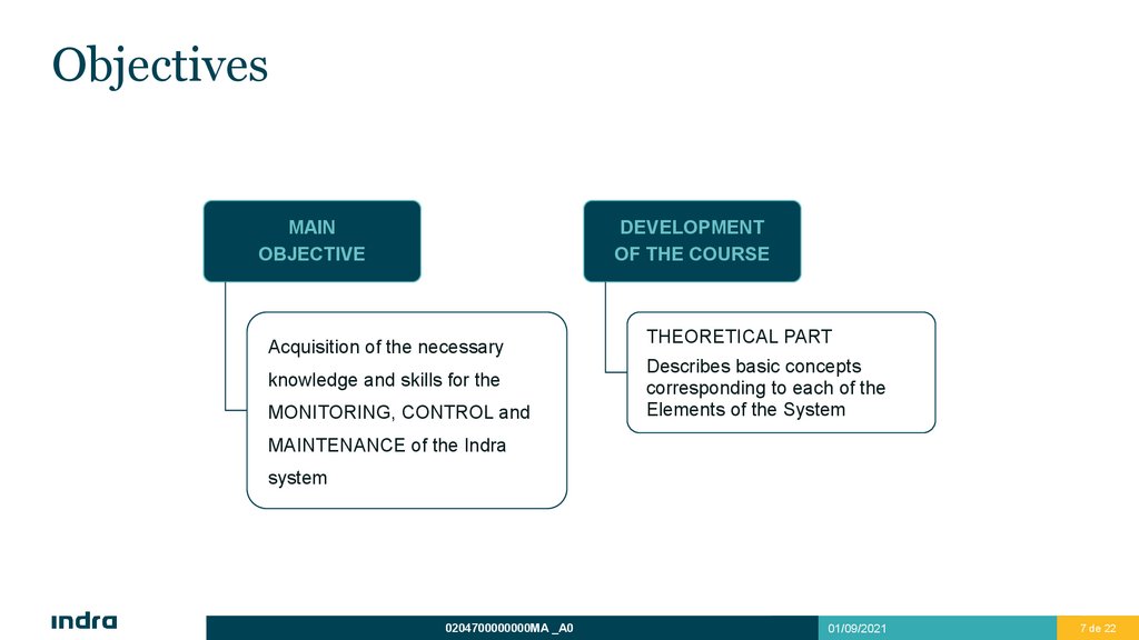
ObjectivesMAIN
OBJECTIVE
DEVELOPMENT
OF THE COURSE
Acquisition of the necessary
knowledge and skills for the
MONITORING, CONTROL and
THEORETICAL PART
Describes basic concepts
corresponding to each of the
Elements of the System
MAINTENANCE of the Indra
system
0204700000000MA _A0
01/09/2021
7 de 22
8.
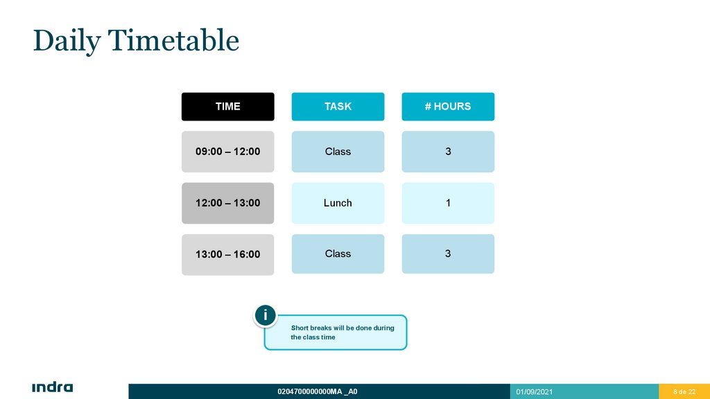
Daily TimetableTIME
TASK
# HOURS
09:00 – 12:00
Class
3
12:00 – 13:00
Lunch
1
13:00 – 16:00
Class
3
i
Short breaks will be done during
the class time
0204700000000MA _A0
01/09/2021
8 de 22
9.
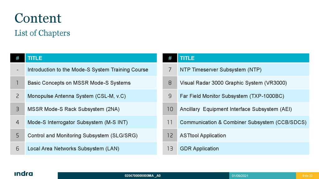
ContentList of Chapters
#
TITLE
#
TITLE
-
Introduction to the Mode-S System Training Course
7
NTP Timeserver Subsystem (NTP)
1
Basic Concepts on MSSR Mode-S Systems
8
Visual Radar 3000 Graphic System (VR3000)
2
Monopulse Antenna System (CSL-M, v.C)
9
Far Field Monitor Subsystem (TXP-1000BC)
3
MSSR Mode-S Rack Subsystem (2NA)
10
Ancillary Equipment Interface Subsystem (AEI)
4
Mode-S Interrogator Subsystem (M-S INT)
11
Communication & Combiner Subsystem (CCB/SDCS)
5
Control and Monitoring Subsystem (SLG/SRG)
12
ASTtool Application
6
Local Area Networks Subsystem (LAN)
13
GDR Application
0204700000000MA _A0
01/09/2021
9 de 22
10.
AgendaDaily Tasks - 1st Week
# DAY
CHAPTERS
1
• Introduction to the Mode-S System Training Course
• Basic Concepts on MSSR Mode-S Systems
2
• Monopulse Antenna System (CSL-M, v.C)
• MSSR Mode-S Rack Subsystem (2NA)
3
• Mode-S Interrogator Subsystem (M-S INT) – Part I
4
• Mode-S Interrogator Subsystem (M-S INT) – Part II
5
• Mode-S Interrogator Subsystem (M-S INT) – Part III
0204700000000MA _A0
01/09/2021
10 de 22
11.
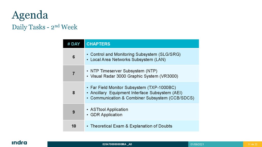
AgendaDaily Tasks - 2nd Week
# DAY
CHAPTERS
6
• Control and Monitoring Subsystem (SLG/SRG)
• Local Area Networks Subsystem (LAN)
7
• NTP Timeserver Subsystem (NTP)
• Visual Radar 3000 Graphic System (VR3000)
8
• Far Field Monitor Subsystem (TXP-1000BC)
• Ancillary Equipment Interface Subsystem (AEI)
• Communication & Combiner Subsystem (CCB/SDCS)
9
• ASTtool Application
• GDR Application
10
• Theoretical Exam & Explanation of Doubts
0204700000000MA _A0
01/09/2021
11 de 22
12.
Mode-S SystemOverview
System Architecture Overview
Control & Monitoring Overview
Maintenance Overview
Alignment & Adjustment Overview
Performance Verification Overview
2
13.
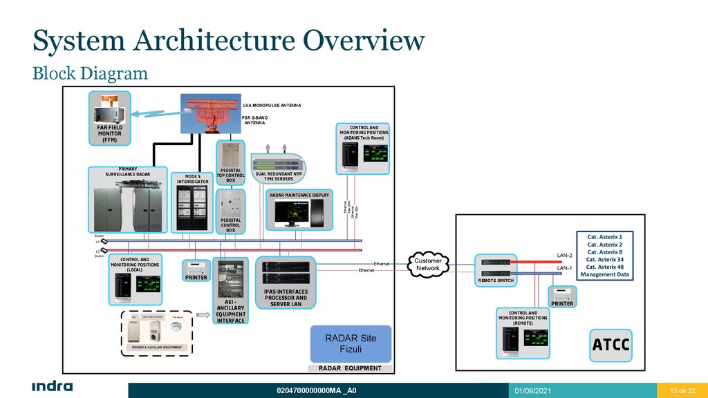
System Architecture OverviewBlock Diagram
LVA MONOPULSE ANTENNA
PSR S-BAND
ANTENNA
FAR FIELD
MONITOR
(FFM)
CONTROL AND
MONITORING POSITIONS
(AZANS Tech Room)
PRIMARY
SURVEILLANCE RADAR
MODE S
INTERROGATOR
PEDESTAL
TOP CONTROL
BOX
DUAL REDUNDANT NTP
TIME SERVERS
Ethernet
Max 80m
Ethernet
Max 80m
RADAR MAINTENACE DISPLAY
PEDESTAL
CONTROL
BOX
Switch
L1
L2
Switch
LAN-2
CONTROL AND
MONITORING POSITIONS
(LOCAL)
Ethernet
Ethernet
PRINTER
UPS
AIR CONDITIONING
FIre Alarm
POWER & AUXILIAR EQUIPMENT
Customer
Network
LAN-1
Cat. Asterix 1
Cat. Asterix 2
Cat. Asterix 8
Cat. Asterix 34
Cat. Asterix 48
Management Data
REMOTE SWITCH
AEI –
ANCILLARY
EQUIPMENT
INTERFACE
IPAS-INTERFACES
PROCESSOR AND
SERVER LAN
PRINTER
CONTROL AND
MONITORING POSITIONS
(REMOTE)
ATCC
RADAR Site
Fizuli
RADAR EQUIPMENT
0204700000000MA _A0
01/09/2021
13 de 22
14.
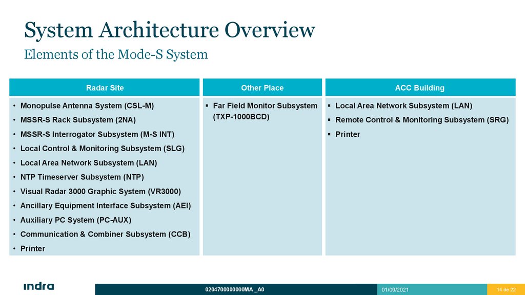
System Architecture OverviewElements of the Mode-S System
Radar Site
• Monopulse Antenna System (CSL-M)
• MSSR-S Rack Subsystem (2NA)
Other Place
Far Field Monitor Subsystem
(TXP-1000BCD)
• MSSR-S Interrogator Subsystem (M-S INT)
ACC Building
Local Area Network Subsystem (LAN)
Remote Control & Monitoring Subsystem (SRG)
Printer
• Local Control & Monitoring Subsystem (SLG)
• Local Area Network Subsystem (LAN)
• NTP Timeserver Subsystem (NTP)
• Visual Radar 3000 Graphic System (VR3000)
• Ancillary Equipment Interface Subsystem (AEI)
• Auxiliary PC System (PC-AUX)
• Communication & Combiner Subsystem (CCB)
• Printer
0204700000000MA _A0
01/09/2021
14 de 22
15.
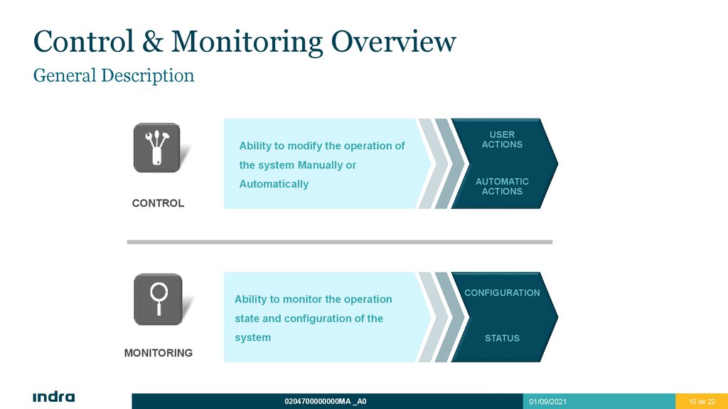
Control & Monitoring OverviewGeneral Description
Ability to modify the operation of
USER
ACTIONS
the system Manually or
Automatically
AUTOMATIC
ACTIONS
CONTROL
Ability to monitor the operation
CONFIGURATION
state and configuration of the
system
STATUS
MONITORING
0204700000000MA _A0
01/09/2021
15 de 22
16.
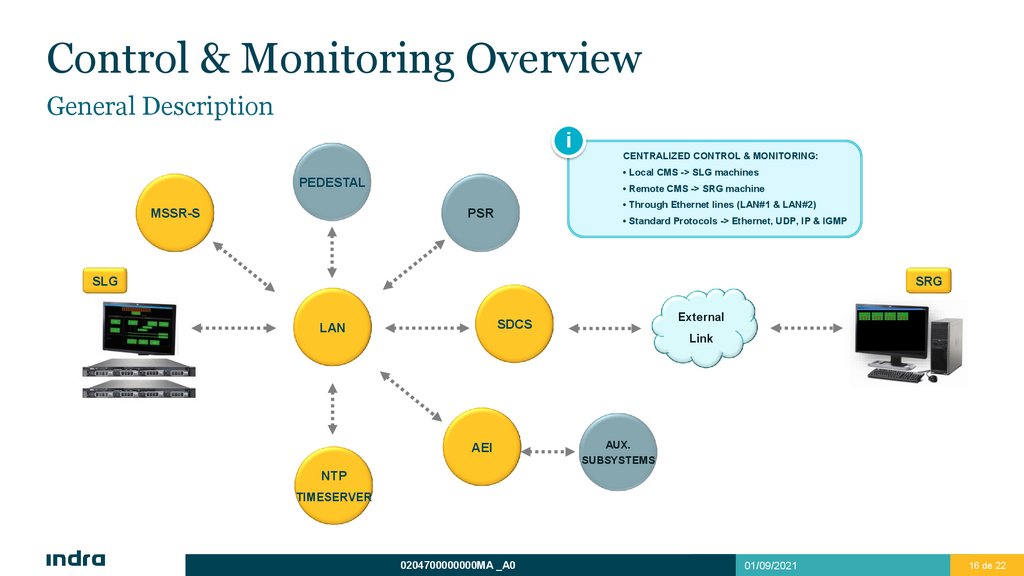
Control & Monitoring OverviewGeneral Description
i
CENTRALIZED CONTROL & MONITORING:
• Local CMS -> SLG machines
PEDESTAL
MSSR-S
• Remote CMS -> SRG machine
• Through Ethernet lines (LAN#1 & LAN#2)
PSR
• Standard Protocols -> Ethernet, UDP, IP & IGMP
SLG
SRG
External
SDCS
LAN
Link
AEI
AUX.
SUBSYSTEMS
NTP
TIMESERVER
0204700000000MA _A0
01/09/2021
16 de 22
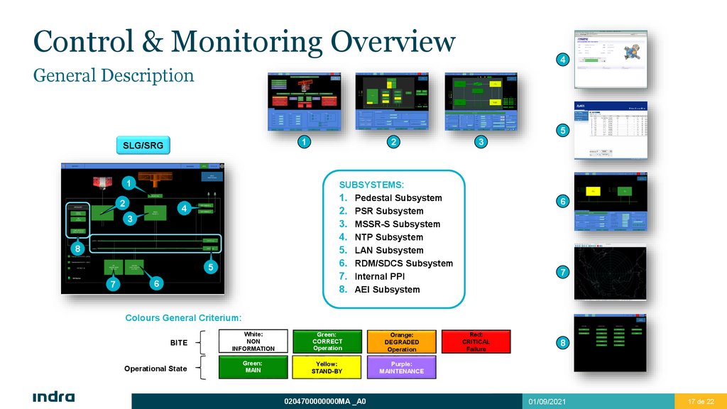
17.
Control & Monitoring Overview4
General Description
5
1
SLG/SRG
1
2
3
SUBSYSTEMS:
1. Pedestal Subsystem
2. PSR Subsystem
3. MSSR-S Subsystem
4. NTP Subsystem
5. LAN Subsystem
6. RDM/SDCS Subsystem
7. Internal PPI
8. AEI Subsystem
4
3
8
5
DB Replica
7
2
6
6
7
Colours General Criterium:
BITE
Operational State
White:
NON
INFORMATION
Green:
CORRECT
Operation
Orange:
DEGRADED
Operation
Green:
MAIN
Yellow:
STAND-BY
Purple:
MAINTENANCE
0204700000000MA _A0
Red:
CRITICAL
Failure
8
01/09/2021
17 de 22
18.
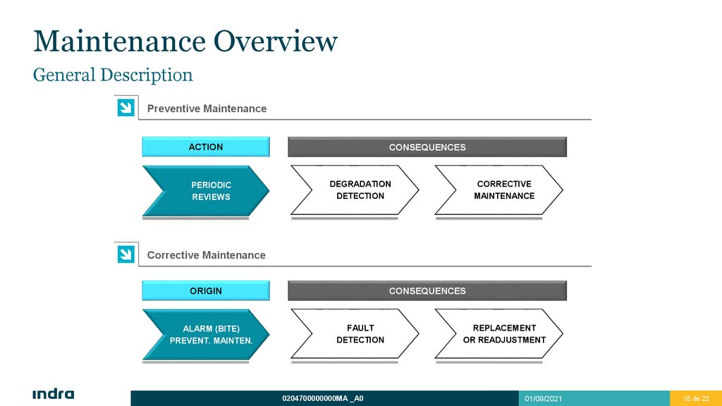
Maintenance OverviewGeneral Description
Preventive Maintenance
ACTION
PERIODIC
REVIEWS
CONSEQUENCES
DEGRADATION
DETECTION
CORRECTIVE
MAINTENANCE
Corrective Maintenance
ORIGIN
ALARM (BITE)
PREVENT. MAINTEN.
CONSEQUENCES
FAULT
DETECTION
0204700000000MA _A0
REPLACEMENT
OR READJUSTMENT
01/09/2021
18 de 22
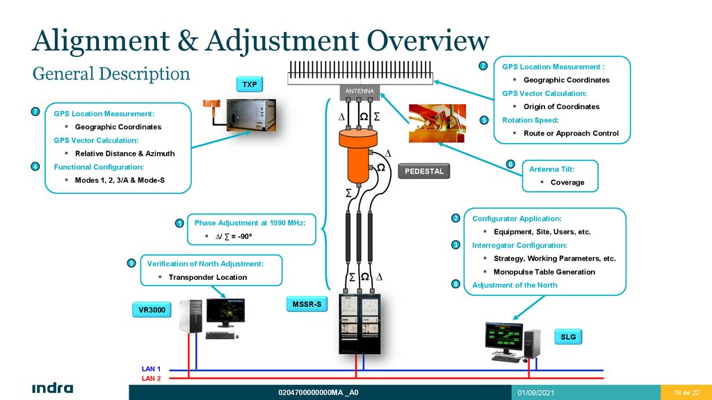
19.
Alignment & Adjustment OverviewGeneral Description
7
Geographic Coordinates
TXP
ANTENNA
7
GPS Location Measurement :
Geographic Coordinates
Origin of Coordinates
Ω ∑
∆
GPS Location Measurement:
GPS Vector Calculation:
5
Rotation Speed:
Route or Approach Control
GPS Vector Calculation:
∆
Ω
Relative Distance & Azimuth
4
Functional Configuration:
6
PEDESTAL
Modes 1, 2, 3/A & Mode-S
Antenna Tilt:
Coverage
∑
1
2
Phase Adjustment at 1090 MHz:
Equipment, Site, Users, etc.
∆/ ∑ = -90º
3
9
Interrogator Configuration:
Strategy, Working Parameters, etc.
Verification of North Adjustment:
∑ Ω ∆
Transponder Location
VR3000
Configurator Application:
Monopulse Table Generation
8
Adjustment of the North
MSSR-S
SLG
LAN 1
LAN 2
0204700000000MA _A0
01/09/2021
19 de 22
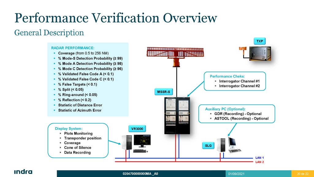
20.
Performance Verification OverviewGeneral Description
TXP
RADAR PERFORMANCE:
Coverage (from 0.5 to 256 NM)
% Mode-S Detection Probability (≥ 99)
% Mode A Detection Probability (≥ 98)
% Mode C Detection Probability (≥ 96)
% Validated False Code A (< 0.1)
% Validated False Code C (< 0.1)
% False Targets (< 0.1)
% Split (< 0.05)
% Ring-around (< 0.05)
% Reflection (< 0.2)
Statistic of Distance Error
Statistic of Azimuth Error
Display System:
Plots Monitoring
Transponder position
Coverage
Cone of Silence
Data Recording
Performance Cheks:
Interrogator Channel #1
Interrogator Channel #2
MSSR-S
Auxiliary PC (Optional):
GDR (Recording) - Optional
ASTOOL (Recording) - Optional
VR3000
SLG
LAN 1
LAN 2
0204700000000MA _A0
01/09/2021
20 de 22
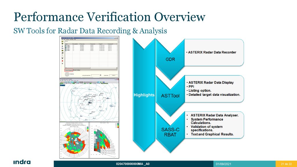
21.
Performance Verification OverviewSW Tools for Radar Data Recording & Analysis
0204700000000MA _A0
01/09/2021
21 de 22
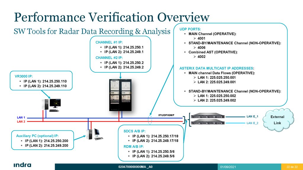
22.
Performance Verification OverviewSW Tools for Radar Data Recording & Analysis
CHANNEL #1 IP:
IP (LAN 1): 214.25.250.1
IP (LAN 2): 214.25.249.1
CHANNEL #2 IP:
IP (LAN 1): 214.25.250.2
IP (LAN 2): 214.25.249.2
UDP PORTS:
MAIN Channel (OPERATIVE):
4001
STAND-BY/MAINTENANCE Channel (NON-OPERATIVE):
4006
Combined AST (OPERATIVE):
4002
ASTERIX DATA MULTICAST IP ADDRESSES:
MAIN channel Data Flows (OPERATIVE):
LAN 1: 225.025.250.001
LAN 2: 225.025.249.001
VR3000 IP:
IP (LAN 1): 214.25.250.110
IP (LAN 2): 214.25.249.110
STAND-BY/MAINTENANCE Channel (NON-OPERATIVE):
LAN 1: 225.025.250.002
LAN 2: 225.025.249.002
IP/UDP/IGMP
LAN 1
LAN 2
Auxiliary PC (optional) IP:
IP (LAN 1): 214.25.250.200
IP (LAN 2): 214.25.249.200
LAN E_1
External
LAN E_2
Link
SDCS A/B IP:
IP (LAN 1): 214.25.250.17/18
IP (LAN 2): 214.25.249.17/18
RDM A/B IP:
IP (LAN 1): 214.25.250.5/6
IP (LAN 2): 214.25.249.5/6
0204700000000MA _A0
01/09/2021
22 de 22