


")


")


")
")
")


 Программное обеспечение
 Электроника
Похожие презентации:


")


")
Netwave systems B.V. Maritime information technology
1.
Netwave Systems B.V.Maritime Information Technology
2.
Video set up for NW-6044 Video Interface (option)This presentation will demonstrate and explain how to set
up VGA connected sources via this module
The module has to be connected to your own laptop in
order to create the necessary files which can be uploaded
later into the core module.
3.
This interface has 4 input portsfor capturing images from a
dedicated buffered output port
of the video source
If more than 1 source is specified by the
MAXSOURCES entry, then Control
Input/Output connector signals are used to
indicate the currently active source. The video
signal configuration is read and a new image is
captured. If the system is configured for 2 or
more video channels, then the next channel in
the sequence is selected
VCS2 software program has to be used on laptop in
order to configure the set up’s for x band, s band
and ecdis images
4. Set-Up Laptop for Video Module Connection
1. Connect the laptop to the Ethernet port (labeled “Output”) located at the frontof the Video Module.
2. On the laptop’s desktop screen, open network and sharing center.
3. Press change adapter settings
4. Choose local area and open properties
5. Select TCP/IPv4
6. Put the IP in this designated fixed one; 192.168.199.1
7. Set the subnet mask to; 255.255.255.0
8. Press ok, ping the module on 192.168.199.228
9. put off your fire wall in case of connection problems
5. Video Module Specifications
Max Image Size1600 X 1200
24-bit
85Hz
Interleaved Max Size
1920x1280 (2 Images)
24-bit
170Hz
6. Video Module Input Signals
RGBHVSeparate Red, Green, Blue, Hsync & Vsync
Composite SOG
RGB combined with Hsync &Vsync
Green combined with Hsync &Vsync
NTSC Composite (Green Only)
7.
8.
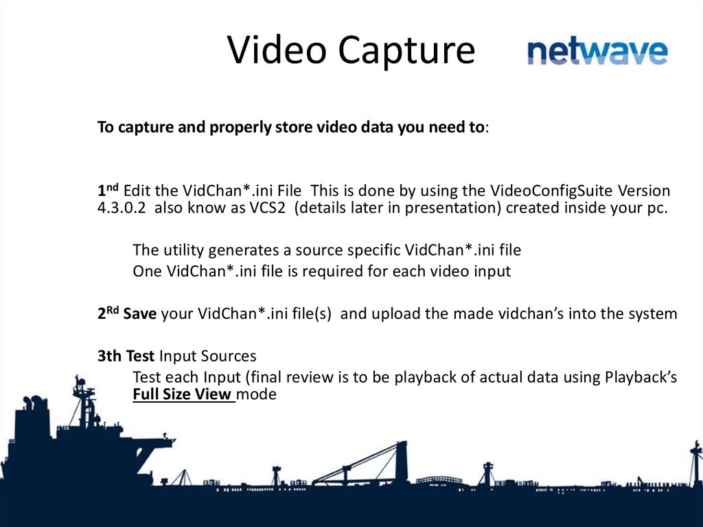
Video CaptureTo capture and properly store video data you need to:
1nd Edit the VidChan*.ini File This is done by using the VideoConfigSuite Version
4.3.0.2 also know as VCS2 (details later in presentation) created inside your pc.
The utility generates a source specific VidChan*.ini file
One VidChan*.ini file is required for each video input
2Rd Save your VidChan*.ini file(s) and upload the made vidchan’s into the system
3th Test Input Sources
Test each Input (final review is to be playback of actual data using Playback’s
Full Size View mode
9.
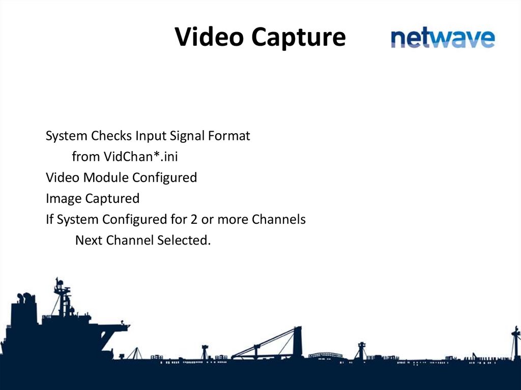
Video CaptureSystem Checks Input Signal Format
from VidChan*.ini
Video Module Configured
Image Captured
If System Configured for 2 or more Channels
Next Channel Selected.
10. VideoConfigSuite 4.3.0.2 (VCS2)
The suite runs from the executable file: VCS2.exe andrequires no other supporting files.
Has a built-in AutoDetection routine which detects many of
the necessary parameters for the <VidChanX.ini> files
Existing <VidChanX.ini> files can also be directly modified
within this application (as they are text files)
11. VideoConfigSuite VCS2 – User Interfaces
12. VCS2 – User Interfaces
The suite consists of five tab accessed sections:1.) Configuration (for video capture)
2.) Sizing (image size and shape)
3.) Adjustments (image quality)
4.) Info (provides statistics on capture
image)
13.
VCS2 – Configuration Tab14. VCS2 – Configuration Tab
Video Configuration automatically attempts to detect the videoinput on channel 1
To change the channel selection, click the radio button next to
the number of the desired channel
To create settings for a new channel click New Video Channel
button. If the channel uses Composite Syncs, select the
“Composite” check box and use the associated radio buttons to
indicate whether the composite sync is:
- On a separate TTL output; or
- SOG, Encoded in the input on the video channel
15. VCS2 – Configuration Tab
If auto detection is successful the image will be displayed in the Capture area,and the Auto-Detection Status configuration data fields will display the
appropriate information.
If the auto detection fails, the capture must be manually configured.
1.) Select a different Configuration Mode from the
Configuration Mode drop list
2.) If you know the values of VSYNC and HSYNC, select
Manual Configuration mode (The fail safe modes may help if you are unsure
of the VSYNC and HSYNC rates.)
3.) Enter the VSYNC and HSYNC values
4.) Press Validate
5.)To load from a previous <VidchanX.ini> file,
Select Manual Configuration mode; and
Press the “Load from INI button” and select the desired file.
16.
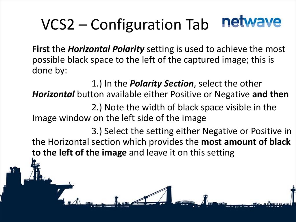
VCS2 – Configuration TabFirst the Horizontal Polarity setting is used to achieve the most
possible black space to the left of the captured image; this is
done by:
1.) In the Polarity Section, select the other
Horizontal button available either Positive or Negative and then
2.) Note the width of black space visible in the
Image window on the left side of the image
3.) Select the setting either Negative or Positive in
the Horizontal section which provides the most amount of black
to the left of the image and leave it on this setting
17. VCS2 – Configuration Tab
Use the Vertical Polarity setting to correct skewed images such that on right1.) Select Pos in the Vertical Section of the Polarity Selection
2.) If the skewing is not corrected, select Neg in the Vertical
Section of the Polarity Selection
3.) Note which setting establishes a correct image with sides
at right angles to each other and leave it on that setting
18. VCS2 – Sizing Tab
19. VCS2 – Sizing Tab - H&V Offsets
VCS2 – Sizing Tab - H&V OffsetsTo capture the entire image, the image size and offset
values must be adjusted using the controls under the
Sizing tab
A proper capture should fill the Capture window and
keep all 4 edges of the image within the Capture
window (leaving a small bit of black all around the
image)
20. VCS2 – Sizing Tab - H&V Offsets
VCS2 – Sizing Tab - H&V OffsetsFirst, adjust the Horizontal and Vertical offset as follows:
1.) Press “Start” button in the Horizontal/Vertical Offset section
2.) Click OK to warning which appears
3.) Position the cross-hair on the top-left corner of the image by
clicking on the top-left corner of the image in the Capture window.
Horizontal and vertical values (co-ordinates will display in the Capture
window)
4.) May also adjust the position of the cross-hair by changing the
New Offset text entry boxes for the X and Y values in the
Horizontal/Vertical Offset section
5.) Click the Apply button in the Horizontal/Vertical Offset section
and image will automatically re-adjust.
6.) Image should now be in the upper right hand corner
21. VCS2 – Sizing Tab - Dimensions
Second, If part of the image is not visible in the Capture window after it is movedto the upper left corner, it shall be necessary to adjust the image height and/or
width as follows :
Sizing page
1.) Click the “Start” button on the Dimensions section of the
2.) Click OK to warning which appears
3.) Click and drag the cursor on the image to reveal a rectangle
that defines the image size
4.) Click and drag the rectangle in the red transparent area
5.) Pan the image outside the current viewing area to select a
larger size
6.) Alternatively, enter a Width and Height number in boxes
7.) Click the Apply button in the lower right corner of the
Dimensions section
8.) “Extents Changed” dialogue box confirms that the image
size is adjusted now click OK
22. VCS2 – Sizing Tab - Dimensions
Adjust Widthand Height
in the
Dimensions
section until
a only a
small
amount of
black
surrounds
the image
23. VCS2 – Sizing Tab – Interlaced Image
A video source may provide a captured interlaced image like the one belowThe captured image appears vertically 2 or 3 times within the Capture window
24. VCS2 – Sizing Utility – Interlaced Image
To adjust a captured interlaced image, complete the followingsteps:
1.) On the Configuration Page; set the Vertical
Polarity to the same setting (negative or positive) as indicated in
the Auto-Detection Information Box
2.) Repeat for the Horizontal Polarity setting
3.) If the images captured are not fully visible,
then the image height must be adjusted by:
- Click the Sizing tab to open the Sizing page
- Click Start button in the Dimensions section
- Increase the image height to make this lower
image visible
- Adjust Image Dimensions as written above; and
- Adjust height as necessary
25. VCS2 – Sizing Utility – Interlaced Image
Adjust height of image on left toallow two entire images in
capture window as shown on
right
26. VCS2 – Sizing Tab – Interlaced Image
1.) Once the images are entirely visible; Ensure a small amount of black space stillappears at the top of the Capture window
2.) Zoom in on upper image
3.) Use the scrollbars to pan the image and find the top edge of the upper image
4.) Click the From Image button under the Line 0 Start scroll box
5.) Message will allow user to click a point to find the top edge of the image
6.) Once the top edge of the image is found, scroll down to the lower image
7.) Locate the top edge of the lower image using the same process; this time click the
From Image button in the Line 1 Start section instead for the lower image
8.) Image values have now been set; Click the Interlaced checkbox on the Sizing tab
page
9.) The interlaced images automatically merge into a single image
10.) Adjust pixel value of Line 0 by up or down one if image is blurry
11.) You may then have to adjust the Sizing pages H/V offsets and W/H dimensions to
perfect your capture
27. VCS2 Sizing Tab – Interleaved Image
If the capturedimage has a
resolution of 1600 x
1200 pixels or
greater, it may
appear repeated
within the Capture
window shown on
right
28. VCS2 Sizing Tab – Interleaved Image
In order to correct this image it must be properly interleaved. Complete thefollowing steps:
1.) Click the Sizing tab to open the Sizing page
2.) Click the Start button in the Horizontal/Vertical Offset
section
3.) Use the New Offset X scroll box and Y scroll box to move
the image as close to the top left hand corner of the Capture
window
Skip dimensions!!
4.) Use Zooming options, determine the top edge of both images.
As was done for interlaced image, except
Line 0 Start is usually be left at 0 and Line 1 Start should be
adjusted
5.) Click the Interleaved checkbox to activate Interleaved mode
6.) If the image blurry, adjust Line 1 Start one value at a time until
it looks correct.
29. VCS2 Sizing Tab – Recalibration
The following steps are used to recalibrate the captured image:1.) Locate a circle in the radar image. A Variable Range Marker (VRM) or
range ring, available on most radar images are good.
2.) Click the Start button in the Recalibration section at the bottom of the
Sizing page
3.) In the Capture window click the Pick Points button to select the 4
points of the circle in order.
4.) When 4 points of the circle are selected, click the Apply button and
this applies the adjusted value of the Phase Lock Loop (PLL) Multiplier Number
(N)
5.) Retry step 4 if necessary until image aspect ratio is correct
6.) Adjust H/V Offset until image is in the upper left corner of the capture
window.
Note: With many radar images, it may be difficult to determine the true upper left
corner of the captured image. The installer may have to adjust the image’s
position a number of times to ensure it is as close as possible to the top left
corner without losing any part of the image.
30. VCS2 – Sizing Tab – Recalibration
Correct aspect ratio afterrecalibration (top) and final
recalibrated image with
Image Offsets adjusted on
the right
31. VCS2 – Adjustments Tab
32.
VCS2Adjustments Tab – Sharpness - Phase
The Sharpness section offers three scroll boxes to adjust the Phase,
charge pump (CPMP), and the voltage controlled oscillators (VCO).
1.) Phase
If image displays pixilation (visible noise), banding,
and/or soft edges. This means the image phase must be adjusted.
To adjust the Phase:
- Enter a value or clicking the up/down controls on
the Phase scroll box (The range available for adjustment is 0 to 31.);
- The image changes immediately to reflect the
change. Continue to adjust the number until the image is sharp.
33.
VCS2Adjustments Tab – Sharpness - CPMP
2.) CPMP (Charge Pump)
When the image phase is sharpened, minor oscillation
may still appear in the image. If so it may be necessary to adjust the
image CPMP:
- Check for oscillations at either the top of the image or
near any straight black lines where they are most apparent
- Note the image quality and use the CPMP scroll box to
set CPMP between 0 and 3
- Image is automatically updated to show change
- Note the image quality for improvement; and
- Make further adjustments as necessary
34. VCS2 Adjustments Tab – Sharpness – Voltage Controlled Oscillator (VCO)
3.) VCONOTE: The VCO setting should NOT be adjusted
unless the captured image is severely distorted
- The VCO scroll box allows the installer to adjust
the voltage controlled oscillator. The range available for
adjustment is 0 (default) to 3
35. VCS2 Adjustments Tab – Gain/Offset
To create a more uniform image, the installer can finetune the gain and/or offset in the Gain/OffsetAdjustment section. This section includes:
- A histogram.
- Red, Green and Blue Gain and Offset
controls; and
- A Master Gain and Master Offset
control.
36. VCS2 Adjustments Tab – Gain/Offset
Adjusting individual Red, Green and Blue Gains will shift the hueof the image
Adjusting individual Offsets will shift that color’s image up or
down in the capture window
Adjusting Master Gain stretches the image vertically in the
capture window
Adjusting Master Offset shifts the image up and down in the
capture window
37. VCS2 Adjustments Tab – Gain/Offset
To fine tune the Gain and Offset usingthe histogram of individual Red,
Green, and Blue icons:
1.) Click on the histogram
icon to be adjusted
2.) Drag the icon and
observe changes in the Capture window
image
3.) When the adjustment is
finished, release the icon
4.) Repeat process for each
of the histogram controls until the
captured image is satisfactory
5.) You may also enter
numbers manually in boxes provided
38. VCS2 Adjustments Tab – Gain/Offset
To fine tune the Gain and Offset usingthe Master Gain and Offset scroll
buttons:
1.) Click on the Master Gain
scroll button to adjust the Gain of the
entire image—instead of the individual
Red, Green and Blue values. (The range
is 0 to 255). Adjusting Gain stretches
the image vertically in the Capture
window
2.) Click on the Master Offset
scroll button to adjust the Offset of the
entire image—instead of the individual
Red, Green and Blue values. (The range
is 0 to 255). Adjusting the offset shifts
the image up and down in the Capture
window.
39. VCS2 Adjustments Tab – Clamp
Clamp allows enables or disables the video capture HSync signal default allowsyou to enable VSYNC signal capture if there is no HSYNC signal.
Enable (Use HSYNC) button: Selected by default to use HSYNC
Disable (Positive) button: Selected if no HSYNC; it overrides the HSYNC signal
and disables clamp command
Placement [0-255] and Duration [0-255] scroll boxes: Are only active if Enable
(Use HSYNC) box is selected. They allow for sampling of video to determine
voltage corresponding to image’s black levels
40. VCS2 Adjustments Tab – Coast
In the absence of a VSYNC signal, it may be necessary for the circuitry toobtain the HSYNC signal.
Selected: In the absence of an HSYNC signal, the video capture circuitry will
use the VSYNC signal.
Unselected: This setting overrides the usage of the VSYNC signal and,
effectively, disables the “Coast” command.
41. VCS2 – VDR Params Tab
This tab is only to be used in Ruttersystems!!
Skip for NW6000 pls…
42. VCS2 – VDR Info Tab
Info tab page providesstatistics on the capture
image:
-Histogram
-Cross-Section showing
min and max RGB values
-Channel Selection can
enable disable color
channels
-Status Info: size, cursor,
zoom, etc.
43. Special Case – Sync-on-Green (SOG)
If a video source transmits via Sync-on-Green (SOG), theassociated <VidChanX.ini >file must be adjusted to include the
following parameters information:
[CLOCK]
HsRate1=xx.xxx
XDim1=512
YDim1=800
[SYNCS]
Source1=AD9887
N1=yyyy
44. Special Case – Sync-on-Green (SOG)
The HSYNC value (HsRate1=xx.xxx) is obtained from the VideoConfig Suite application. The overall x dimension (N1=yyyy) is
selected based upon the following HSync information:
- For HSync < 50: Set to 1200
- For HSync between 50 to 70: Set to 1400
- For HSync > 70: Set to 1600
45. Special Case – Sync-on-Green (SOG)
It is recommended to use actual HSync value from the manufacturer’s radar (for example, theSTN Atlas 9600 radar has a HSync of 37.5000 KHz). If HSync information is not immediately
available from the radar manufacturer, complete the following procedure:
1.) In the VCS2’s Configuration tab page, under the Configuration group, select “Composite”
2.) Select the “SOG” radio button
3.) HSync and VSync values will appear in the Auto-Detection Status group
4.) Record the HSync value and its polarity
5.) Select Manual Configuration mode
6.) Enter the HSync information and parameters information discussed earlier into the
applicable <VidChanX.ini >file;
7. Save the file;
8.) Click the Load <VidChanX.ini> file; and
9.) Choose the <VidChanX.ini >file which was altered and saved in Step 7 above
NOTE: The above procedure provides an image in the VCS2 application that can now be properly
configured.
46. Uploading vidchan’s
Reconnect the video module to the VDR, connect your Laptop tot the VDR set upright IP and start VDR playback program.
Bhe video configuration
****Pls upload always 4 vidchan*.ini files browse to; setup>video and update
Create empty default 4th file when input is not used !***
47. LWE video sources
1. Make sure to have the latest configuration on your computer, press“Download from VDR” to obtain this configuration from the Core Module.
2. Make sure all video channels are enabled and are sending data over the
VDR network.
3. Press “Probe”, the VDR will now search for all available video channels.
4. The video channels will become visible in the device tree, based on the
configured identifiers (i.e EC0001 and RA0001)
48.
49.
6. Based on the information from the device, the Description, location, sourceand timeout field will be preconfigured, please update to ensure a correct
representation of the situation on board the vessel.
7. Please set the appropriate values for Group, and timeout:
a. Group: (not required) If the vessel has multiple bridges, please configure the
video channels per bridge in separate groups.
i. Per group you can and should have one MAIN or ALWAYS device per source
type (Radar, Ecdis, …)
ii. Per group you can additionally configure as many backups as you like.
b. Timeout, please set a appropriate value for timeout in seconds, based on the
interval between images as provided by sender. We recommend to configure
this as ‘interval’ + 30 seconds.
8. Press save to VDR.
50.
Source type: this defines the type of image source that is transmitting themessage. In line with the VDR performance standard, as a minimal requirement
the VDR shall record Ecdis, Sband and Xband radar images.
Mode: As it is not required to record all available image sources at the same
time (only the source used for navigation), the NW-6000 allows for configuration
of MAIN, BACKUP and ALWAYS devices.
1. MAIN: Within a combination of group and source type, this image is stored
when available.
2. BACKUP: Within a combination of group and source type, this image is stored
when the MAIN or ALWAYS device is not available. In the case multiple backup
devices are configured, these will be recorded in turn.
3. ALWAYS: A device can be configured to be recorded at any time