
Похожие презентации:


iRADVC7000/9000s
1.
iRADVC7000/9000s1.Coating error
2.Coating failure at rear side of sleeve
3.Toner leaking
[Cause]
A. Temperature rise inside of the machine
The fluidity of toner inside the developing assembly deteriorates.
This prevents the smooth circulation of toner, and causing toner to tend to remain unmoving inside
the developing assembly.
B. Error in servicing
At the time of replacing the developing assembly, the initialization is performed.
But, a used developing assembly is used for this work.
1
2.
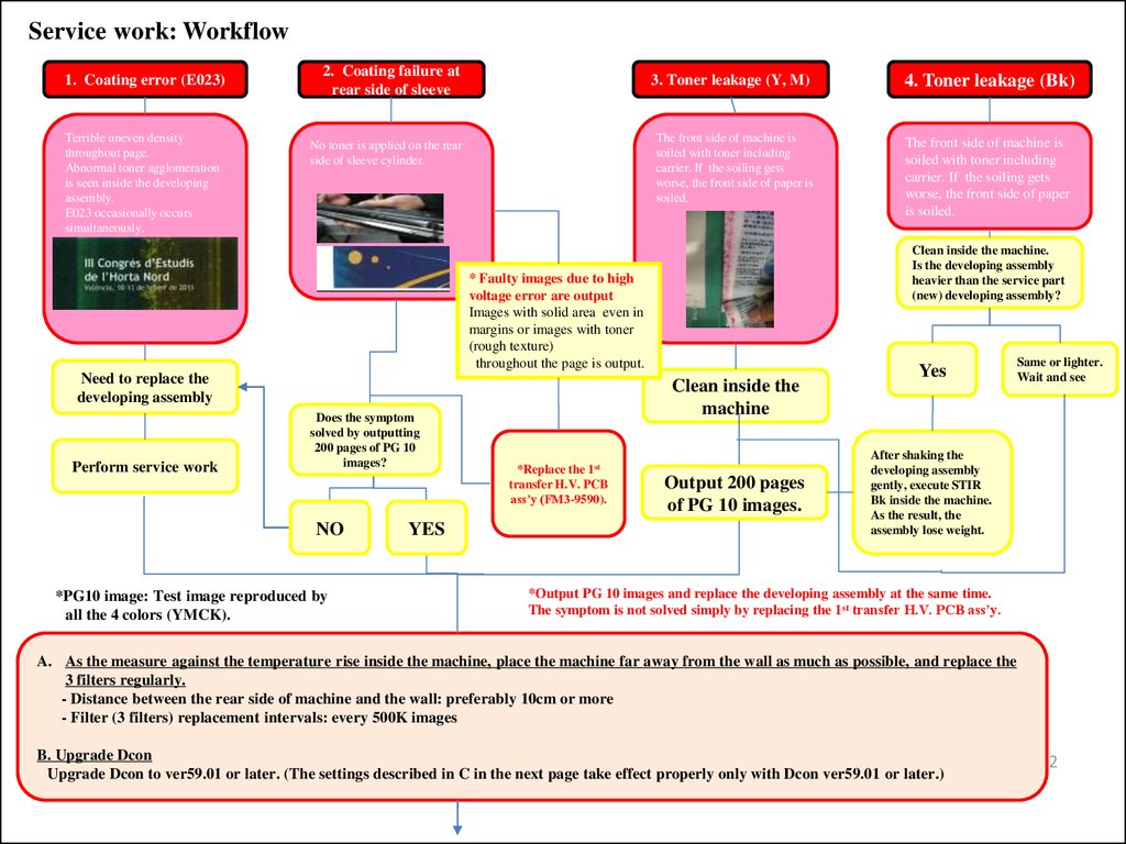
Service work: Workflow1. Coating error (E023)
Terrible uneven density
throughout page.
Abnormal toner agglomeration
is seen inside the developing
assembly.
E023 occasionally occurs
simultaneously.
2. Coating failure at
rear side of sleeve
3. Toner leakage (Y, M)
The front side of machine is
soiled with toner including
carrier. If the soiling gets
worse, the front side of paper is
soiled.
No toner is applied on the rear
side of sleeve cylinder.
Perform service work
Does the symptom
solved by outputting
200 pages of PG 10
images?
NO
*PG10 image: Test image reproduced by
all the 4 colors (YMCK).
YES
Clean inside the
machine
*Replace the 1st
transfer H.V. PCB
ass’y (FM3-9590).
The front side of machine is
soiled with toner including
carrier. If the soiling gets
worse, the front side of paper
is soiled.
Clean inside the machine.
Is the developing assembly
heavier than the service part
(new) developing assembly?
* Faulty images due to high
voltage error are output
Images with solid area even in
margins or images with toner
(rough texture)
throughout the page is output.
Need to replace the
developing assembly
4. Toner leakage (Bk)
Output 200 pages
of PG 10 images.
Yes
Same or lighter.
Wait and see
After shaking the
developing assembly
gently, execute STIR
Bk inside the machine.
As the result, the
assembly lose weight.
*Output PG 10 images and replace the developing assembly at the same time.
The symptom is not solved simply by replacing the 1st transfer H.V. PCB ass’y.
A. As the measure against the temperature rise inside the machine, place the machine far away from the wall as much as possible, and replace the
3 filters regularly.
- Distance between the rear side of machine and the wall: preferably 10cm or more
- Filter (3 filters) replacement intervals: every 500K images
B. Upgrade Dcon
Upgrade Dcon to ver59.01 or later. (The settings described in C in the next page take effect properly only with Dcon ver59.01 or later.)
2
3.
Service work: WorkflowC. Change service mode settings
- Increase the developing assembly stop frequency: Level 1 > Copier > Option> FNC-SW > INTROT-1 > from “200” to “50.”
- Change the TD ratio limiter table: Level 2 > Copier > Adjust > DENS > LLMT-PT > from “0” to “1” (Affected color only).
- Increase toner discharge amount at time of low duty job: Level 2 > Copier > Option > IMG-DEV > DEVL-VTH > from “1” to “2.”
* Pay attention to the waste toner bottle replacement intervals
* If possible, turn off the environment heater (smeared image or deterioration of hue change may occur.)
Relation between LLMT-PT value and T/D ratio control range
Output 25 pages of CA1 chart and then let the machine execute the
post rotation. Repeat this cycle 4 times.
Execute the auto gradation correction
(full correction).
T/D ratio control range
LLMT-PT
Upper limit
Lower limit
-2
-1%
-1%
-1
-3%
-2%
0
Def
Def
1
-2%
-2%
2
-1%
-2%
Notes:
1. If the value of service mode item “SIGG” has been changed, replace the developing assembly of the affected
color, and then perform the initialization on the new developing assembly. This will reset the value of “SIGG”
to the default and the new service mode settings described in “C” above take effect properly.
Level1>COPIER>ADJUST>DENS>SIGG-X
2. If the main power switch is turned off immediately after a large number of pages are output, the temperature
overshoot occurs, and consequently leading to the temperature rise inside the machine.
3
4.
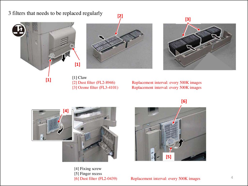
3 filters that needs to be replaced regularly[2]
[3]
[1]
[1] Claw
[2] Dust filter (FL2-8946)
[3] Ozone filter (FL3-4101)
[1]
Replacement interval: every 500K images
Replacement interval: every 500K images
[6]
[4]
[5]
[4] Fixing screw
[5] Finger recess
[6] Dust filter (FL2-0439)
Replacement interval: every 500K images
4
5.
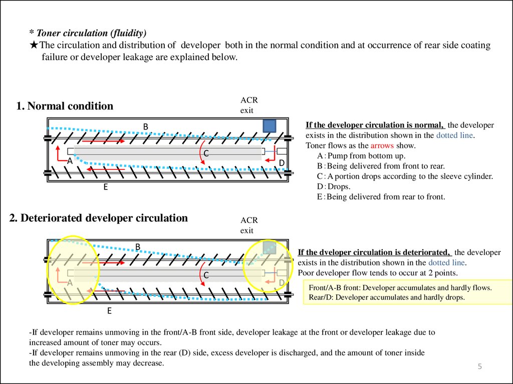
* Toner circulation (fluidity)★The circulation and distribution of developer both in the normal condition and at occurrence of rear side coating
failure or developer leakage are explained below.
ACR
exit
1. Normal condition
B
C
A
D
E
2. Deteriorated developer circulation
ACR
exit
B
C
A
If the developer circulation is normal, the developer
exists in the distribution shown in the dotted line.
Toner flows as the arrows show.
A Pump from bottom up.
B Being delivered from front to rear.
C A portion drops according to the sleeve cylinder.
D Drops.
E Being delivered from rear to front.
If the dveloper circulation is deteriorated, the developer
exists in the distribution shown in the dotted line.
Poor developer flow tends to occur at 2 points.
D
Front/A-B front: Developer accumulates and hardly flows.
Rear/D: Developer accumulates and hardly drops.
E
-If developer remains unmoving in the front/A-B front side, developer leakage at the front or developer leakage due to
increased amount of toner may occurs.
-If developer remains unmoving in the rear (D) side, excess developer is discharged, and the amount of toner inside
the developing assembly may decrease.
5
6.
iRADVC7000/9000s4.White band
5. White lines
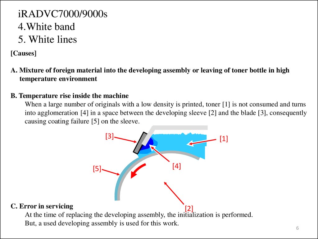
[Causes]
A. Mixture of foreign material into the developing assembly or leaving of toner bottle in high
temperature environment
B. Temperature rise inside the machine
When a large number of originals with a low density is printed, toner [1] is not consumed and turns
into agglomeration [4] in a space between the developing sleeve [2] and the blade [3], consequently
causing coating failure [5] on the sleeve.
[3]
[5]
[1]
[4]
C. Error in servicing
[2]
At the time of replacing the developing assembly, the initialization is performed.
But, a used developing assembly is used for this work.
6
7.
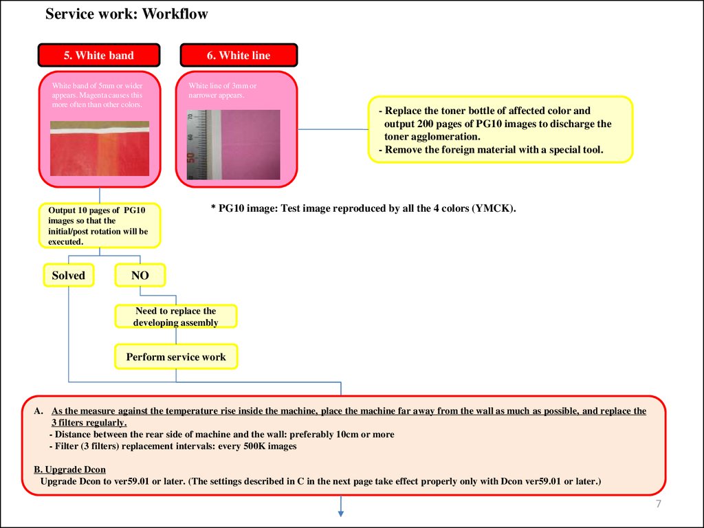
Service work: Workflow5. White band
White band of 5mm or wider
appears. Magenta causes this
more often than other colors.
Output 10 pages of PG10
images so that the
initial/post rotation will be
executed.
Solved
6. White line
White line of 3mm or
narrower appears.
- Replace the toner bottle of affected color and
output 200 pages of PG10 images to discharge the
toner agglomeration.
- Remove the foreign material with a special tool.
* PG10 image: Test image reproduced by all the 4 colors (YMCK).
NO
Need to replace the
developing assembly
Perform service work
A. As the measure against the temperature rise inside the machine, place the machine far away from the wall as much as possible, and replace the
3 filters regularly.
- Distance between the rear side of machine and the wall: preferably 10cm or more
- Filter (3 filters) replacement intervals: every 500K images
B. Upgrade Dcon
Upgrade Dcon to ver59.01 or later. (The settings described in C in the next page take effect properly only with Dcon ver59.01 or later.)
7
8.
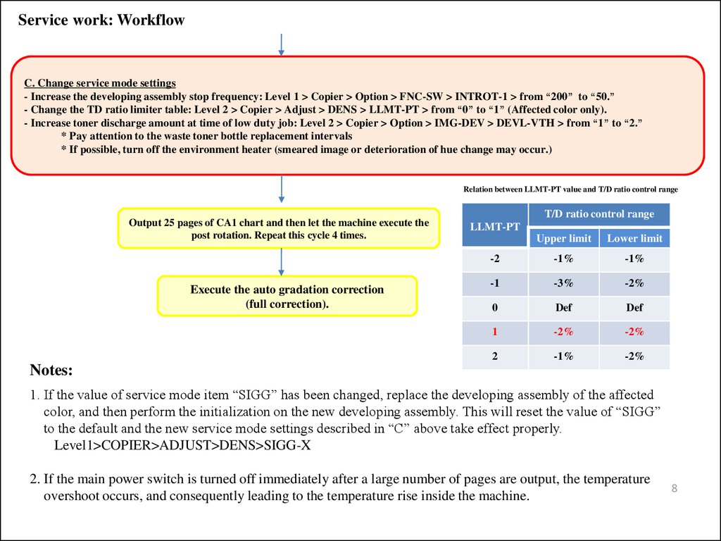
Service work: WorkflowC. Change service mode settings
- Increase the developing assembly stop frequency: Level 1 > Copier > Option > FNC-SW > INTROT-1 > from “200” to “50.”
- Change the TD ratio limiter table: Level 2 > Copier > Adjust > DENS > LLMT-PT > from “0” to “1” (Affected color only).
- Increase toner discharge amount at time of low duty job: Level 2 > Copier > Option > IMG-DEV > DEVL-VTH > from “1” to “2.”
* Pay attention to the waste toner bottle replacement intervals
* If possible, turn off the environment heater (smeared image or deterioration of hue change may occur.)
Relation between LLMT-PT value and T/D ratio control range
Output 25 pages of CA1 chart and then let the machine execute the
post rotation. Repeat this cycle 4 times.
Execute the auto gradation correction
(full correction).
T/D ratio control range
LLMT-PT
Upper limit
Lower limit
-2
-1%
-1%
-1
-3%
-2%
0
Def
Def
1
-2%
-2%
2
-1%
-2%
Notes:
1. If the value of service mode item “SIGG” has been changed, replace the developing assembly of the affected
color, and then perform the initialization on the new developing assembly. This will reset the value of “SIGG”
to the default and the new service mode settings described in “C” above take effect properly.
Level1>COPIER>ADJUST>DENS>SIGG-X
2. If the main power switch is turned off immediately after a large number of pages are output, the temperature
overshoot occurs, and consequently leading to the temperature rise inside the machine.
8
9.
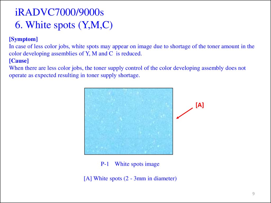
iRADVC7000/9000s6. White spots (Y,M,C)
[Symptom]
In case of less color jobs, white spots may appear on image due to shortage of the toner amount in the
color developing assemblies of Y, M and C is reduced.
[Cause]
When there are less color jobs, the toner supply control of the color developing assembly does not
operate as expected resulting in toner supply shortage.
[A]
P-1 White spots image
[A] White spots (2 - 3mm in diameter)
9
10.
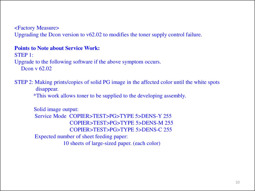
<Factory Measure>Upgrading the Dcon version to v62.02 to modifies the toner supply control failure.
Points to Note about Service Work:
STEP 1:
Upgrade to the following software if the above symptom occurs.
Dcon v 62.02
STEP 2: Making prints/copies of solid PG image in the affected color until the white spots
disappear.
*This work allows toner to be supplied to the developing assembly.
Solid image output:
Service Mode COPIER>TEST>PG>TYPE 5>DENS-Y 255
COPIER>TEST>PG>TYPE 5>DENS-M 255
COPIER>TEST>PG>TYPE 5>DENS-C 255
Expected number of sheet feeding paper:
10 sheets of large-sized paper. (each color)
10