 Промышленность
Похожие презентации:


Laser technologies of Triniti JSC
1.
LASER TECHNOLOGIESof TRINITI JSC
Moscow, Troitsk
Alexander Petrovskiy
Project Manager
2.
1. Mobile laser technological complex (MLTC)2. Solutions for elimination of emergency oil and oilproduct spills in various conditions, including the Arctic
ones, using MLTC
3. Mobile laser technological complex for underwater
cutting
3.
1. Mobile laser technological complex4.
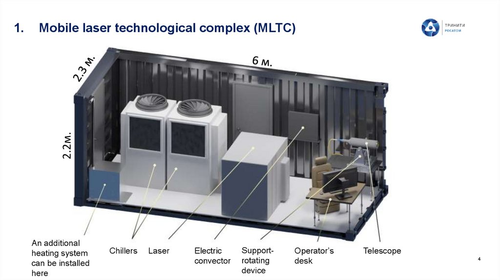
Mobile laser technological complex (MLTC)2.2м.
1.
An additional
heating system
can be installed
here
Chillers
Laser
Electric
convector
Supportrotating
device
Operator’s
desk
Telescope
4
5.
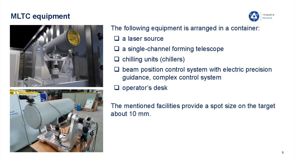
MLTC equipmentThe following equipment is arranged in a container:
a laser source
a single-channel forming telescope
chilling units (chillers)
beam position control system with electric precision
guidance, complex control system
operator’s desk
The mentioned facilities provide a spot size on the target
about 10 mm.
5
6.
MLTC performance capabilitiesRemote laser cutting (up to 300 m):
liquidation of accidents, including those with open gushing, at gas and oil fields;
Cutting (dismantlement) and fragmentation of the large-sized thick-walled metal
and building structures (including submarines and ships);
destruction of ice formations;
elimination of pollution of the coastline and nearshore zone in case of emergency
oil spills.
Remote laser cutting using transport optical fiber (up to 100 m):
fragmentation of equipment (steam generators, reactor vessels etc.) of the
dismantled NPP units;
underwater gas-laser cutting of metal structures.
6
7.
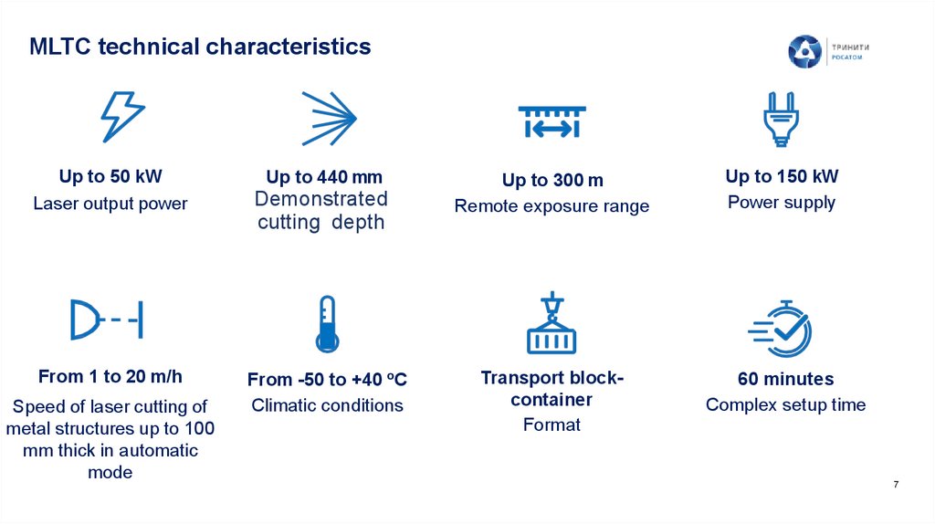
MLTC technical characteristicsUp to 50 kW
Laser output power
From 1 to 20 m/h
Speed of laser cutting of
metal structures up to 100
mm thick in automatic
mode
Up to 440 mm
Demonstrated
cutting depth
From -50 to +40 oС
Climatic conditions
Up to 300 m
Remote exposure range
Up to 150 kW
Power supply
Transport blockcontainer
Format
60 minutes
Complex setup time
7
8.
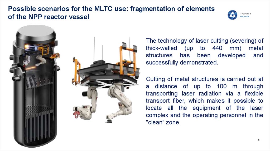
Possible scenarios for the MLTC use: fragmentation of elementsof the NPP reactor vessel
The technology of laser cutting (severing) of
thick-walled (up to 440 mm) metal
structures has been developed and
successfully demonstrated.
Cutting of metal structures is carried out at
a distance of up to 100 m through
transporting laser radiation via a flexible
transport fiber, which makes it possible to
locate all the equipment of the laser
complex and the operating personnel in the
"clean” zone.
8
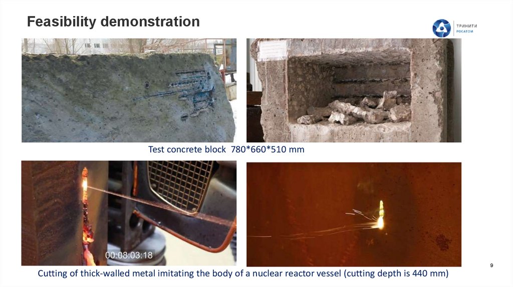
9.
Feasibility demonstrationTest concrete block 780*660*510 mm
9
Cutting of thick-walled metal imitating the body of a nuclear reactor vessel (cutting depth is 440 mm)
10.
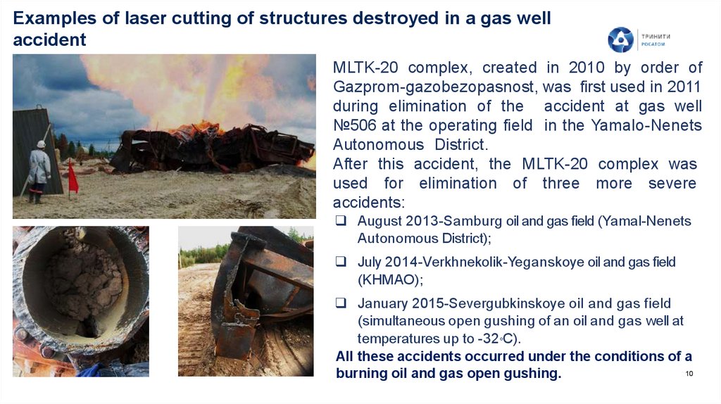
Examples of laser cutting of structures destroyed in a gas wellaccident
MLTK-20 complex, created in 2010 by order of
Gazprom-gazobezopasnost, was first used in 2011
during elimination of the accident at gas well
№506 at the operating field in the Yamalo-Nenets
Autonomous District.
After this accident, the MLTK-20 complex was
used for elimination of three more severe
accidents:
August 2013-Samburg oil and gas field (Yamal-Nenets
Autonomous District);
July 2014-Verkhnekolik-Yeganskoye oil and gas field
(KHMAO);
January 2015-Severgubkinskoye oil and gas field
(simultaneous open gushing of an oil and gas well at
temperatures up to -32 С).
All these accidents occurred under the conditions of a
10
burning oil and gas open gushing.
o
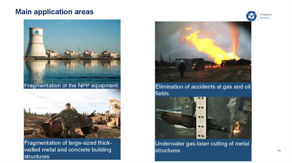
11.
Main application areasFragmentation of the NPP equipment
Elimination of accidents at gas and oil
fields
Fragmentation of large-sized thickwalled metal and concrete building
structures
Underwater gas-laser cutting of metal
structures
11
12.
2. Solutions for elimination of emergency oil and oilproduct spills in various conditions, including theArctic ones, using MLTC
13.
Federal law “On Amendments to Article 46 of the Federal Law "OnEnvironmental Protection“” and certain legislative acts of the Russian
Federation
Art. 1
Paragraph 2. During production, processing, transportation, storage and sale of oil and oil products,
measures should be taken to prevent and eliminate spills of oil and oil products as well as other negative
impacts on the environment.
Paragraph 5. The plan for the prevention and elimination of oil and oil products spills is to be approved by the
organization that produces, processes, transports, stores and sells oil and oil products in the territories
(hereinafter referred to as the operating organization), subject to the availability of:...
approval of the federal executive body authorized to carry out state environmental supervision.
From the explanatory note to the Federal Law:
…instead of the mandatory presence of the conclusion of the state environmental expertise, the draft law
introduces the approval of the draft plan by Rosprirodnadzor, which is more optimal in terms of timeframes
and procedures (for example, it does not require an environmental impact assessment, a simplified
procedure for making changes to the plan).
13
14.
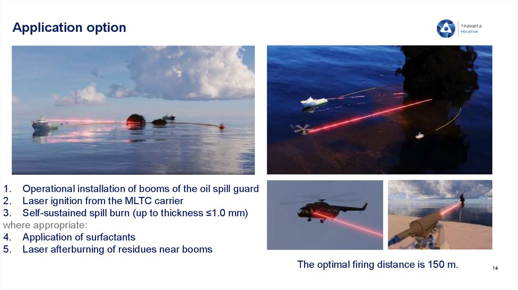
Application option1. Operational installation of booms of the oil spill guard
2. Laser ignition from the MLTC carrier
3. Self-sustained spill burn (up to thickness ≤1.0 mm)
where appropriate:
4. Application of surfactants
5. Laser afterburning of residues near booms
The optimal firing distance is 150 m.
14
15.
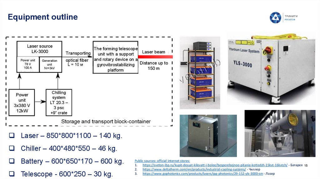
Equipment outlineLaser source
LK-3000
Power unit
78 V
100 A
Power
unit
3x380 V
12kW
Generation
unit
Nr=3kV
Transporting
optical fiber
The forming telescope
Laser beam
unit with a support
and rotary device on a
gyrovibrostabilizing Distance up to
150 m
platform
Chilling
system
LT 20.3 –
3 psc
+9” crate
Storage and transport block-container
Laser – 850*800*1100 – 140 kg.
Chiller – 400*480*550 – 46 kg.
Battery – 600*650*170 – 600 kg.
Telescope - 600*250 – 30 kg.
Public sources: official internet stores:
1. https://sveton-ibp.ru/kupit-desyat-kilovatt-i-bolee/besperebojnoe-pitanie-kottedzh-15kvt-16kvtch/ - Батарея 15
2. https://www.deltatherm.com/en/products/industrial-cooling-systems/ - Чиллер
3. https://www.gophotonics.com/products/lasers/ipg-photonics/29-152-yls-3000-sm - Лазер
16.
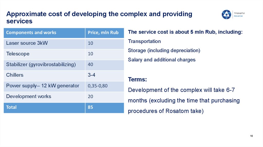
Approximate cost of developing the complex and providingservices
Components and works
Price, mln Rub
The service cost is about 5 mln Rub, including:
Laser source 3kW
10
Transportation
Telescope
10
Stabilizer (gyrovibrostabilizing)
40
Chillers
3-4
Power supply– 12 kW generator
0,35-0,80
Development works
20
Total
85
Storage (including depreciation)
Salary and additional charges
Terms:
Development of the complex will take 6-7
months (excluding the time that purchasing
procedures of Rosatom take)
16
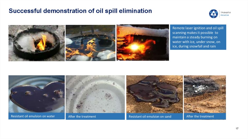
17.
Successful demonstration of oil spill eliminationRemote laser ignition and oil spill
scanning makes it possible to
maintain a steady burning on
water with ice, under snow, on
ice, during snowfall and rain
Resistant oil emulsion on water
After the treatment
Resistant oil emulsion on sand
After the treatment
17
18.
Advantages of laser oil spill eliminationSafety for personnel, due to remote exposure (in the case of the classical method,
when using a flare system, a sufficiently close distance is required).
The ability to burn off the remains of the spill when using surfactants or sorbents
The efficiency of oil spill removal is 90-98% (mechanical means allow to collect no
more than 20-30% of the spilled oil).
In the Arctic conditions, it is impossible to use other methods.
18
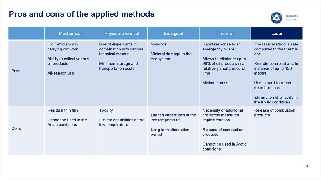
19.
Pros and cons of the applied methodsMechanical
High efficiency in
carrying out work
Ability to collect various
oil products
Pros
Physico-chemical
Use of dispersants in
combination with various
technical means
Biological
Non-toxic
Minimal damage to the
ecosystem
Minimum storage and
transportation costs
All-season use
Thermal
Rapid response to an
emergency oil spill
Allows to eliminate up to
98% of oil products in a
relatively short period of
time
Minimum costs
Laser
The laser method is safe
compared to the thermal
one
Remote control at a safe
distance of up to 150
meters
Use in hard-to-reach
nearshore areas
Elimination of oil spills in
the Arctic conditions
Residual thin film
Cons
Cannot be used in the
Arctic conditions
Toxicity
Limited capabilities at the
low temperature
Limited capabilities at the
low temperature
Necessity of additional
fire safety measures
implementation
Long term elimination
period
Release of combustion
products
Release of combustion
products
Cannot be used in Arctic
conditions
19
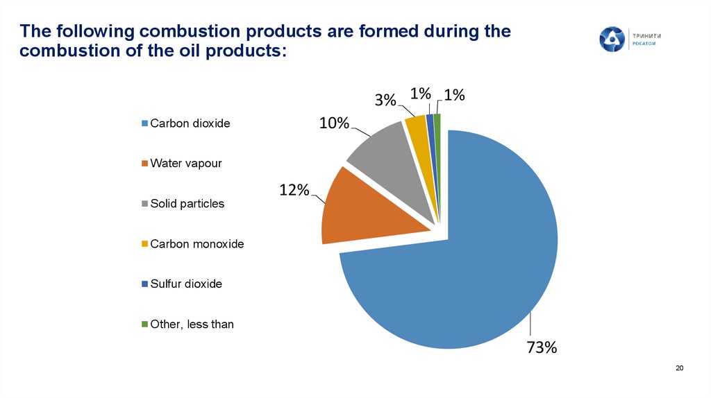
20.
The following combustion products are formed during thecombustion of the oil products:
3% 1% 1%
10%
Сarbon dioxide
Water vapour
Solid particles
12%
Carbon monoxide
Sulfur dioxide
Other, less than
73%
20
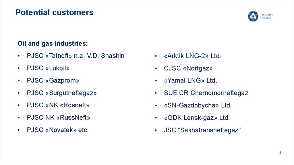
21.
Potential customersOil and gas industries:
PJSC «Tatneft» n.a. V.D. Shashin
«Arktik LNG-2» Ltd.
PJSC «Lukoil»
CJSC «Nortgaz»
PJSC «Gazprom»
«Yamal LNG» Ltd.
PJSC «Surgutneftegaz»
SUE CR Chernomorneftegaz
PJSC «NK «Rosneft»
«SN-Gazdobycha» Ltd.
PJSC NK «RussNeft»
«GDK Lensk-gaz» Ltd.
PJSC «Novatek» etc.
JSC “Sakhatransneftegaz"
21
22.
3. Mobile laser technological complex for underwatercutting
23.
Underwater laser cuttingA Mobile Laser Technology Module (MLTC) has been created in TRINITI JSC.
One of the tasks to be solved by means of MLTC is to provide highly efficient and
safe underwater cutting of thick-walled and bulky metal and reinforced concrete
structures.
MLTC can be used for fragmentation of such objects as:
• radiation-contaminated metal structures of nuclear power plants in the holding
basins;
• shipwrecks;
• underwater elements of port facilities;
• offshore platforms for gas and oil production on the sea shelf (including the
Arctic one).
23
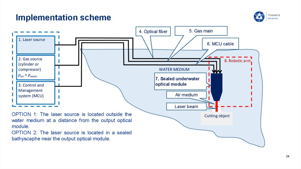
24.
Implementation scheme4. Optical fiber
5. Gas main
1. Laser source
6. MCU cable
2. Gas source
(cylinder or
compressor)
ρair > ρwater
3. Control and
Management
system (MCU)
8. Robotic arm
WATER MEDIUM
7. Sealed underwater
optical module
Air medium
Laser beam
OPTION 1: The laser source is located outside the
water medium at a distance from the output optical
module.
OPTION 2: The laser source is located in a sealed
bathyscaphe near the output optical module.
Cutting object
24
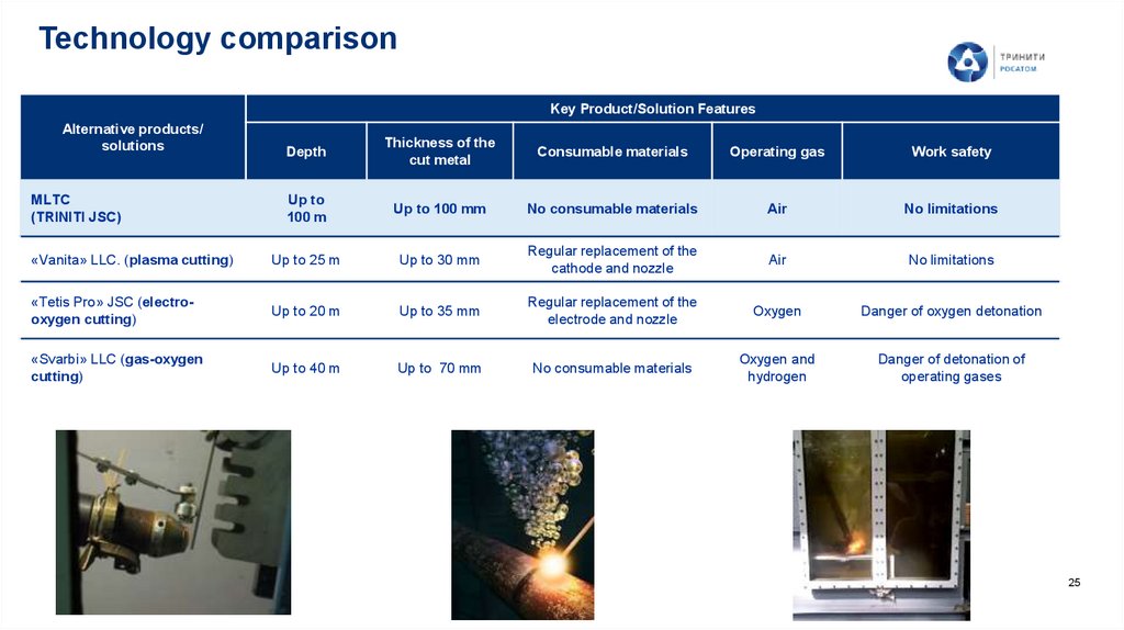
25.
Technology comparisonKey Product/Solution Features
Alternative products/
solutions
Depth
Thickness of the
cut metal
Consumable materials
Operating gas
Work safety
Up to
100 m
Up to 100 mm
No consumable materials
Air
No limitations
«Vanita» LLC. (plasma cutting)
Up to 25 m
Up to 30 mm
Regular replacement of the
cathode and nozzle
Air
No limitations
«Tetis Pro» JSC (electrooxygen cutting)
Up to 20 m
Up to 35 mm
Regular replacement of the
electrode and nozzle
Oxygen
Danger of oxygen detonation
«Svarbi» LLC (gas-oxygen
cutting)
Up to 40 m
Up to 70 mm
No consumable materials
Oxygen and
hydrogen
Danger of detonation of
operating gases
MLTC
(TRINITI JSC)
25
26.
Functions of the underwater robotic arm1)
Delivery of the underwater optical module (UOM) to the cutting site and back.
2)
The initial positioning of the working elements of the output module in relation to the
cutting object.
3)
Moving the working elements of the output module during the cutting process.
4)
Changing the cutting location or cutting object.
5)
Ensuring operation in a wide range of parameters.
The robotic arm is to be developed according to the individual technical specification of the
customer.
It is possible to develop a different versions of the robotic arm for different tasks.
26
The approximate production time is at least 6 months.
27.
THANK YOU FOR YOUR ATTENTIONAlexander Petrovskiy
Project Manager
Alexander Krasyukov
Head of Innovative and Applied
Research Department
Tel.: +7 (495) 841-56-95
Cell.: +7 (910) 409 79 58
E-mail: petrovskiy@triniti.ru
www.triniti.ru
Tel.: +7 (495) 851-06-46
Cell: +7 (916) 924 37 75
E-mail: krasukov@triniti.ru
www.triniti.ru