


 Промышленность
Похожие презентации:


Manufacturing and installation of tanks
1.
Tank equipmentTopic: Manufacturing and installation of tanks
Instructor: Zhanibek Khabbassov
2.
Manufacture and transportation of rolls of tank bottomsand wallsThe rules for the installation of vertical cylindrical steel tanks for oil
and petroleum products PB 03-605-03 provide for the factory
manufacture and subsequent installation of sheet structures of tanks using
the following technological methods:
• rolling method;
• the method of sheet assembly;
• combined method.
3.
Vertical cylindrical steel tanks for oil and petroleum products.This standard establishes requirements for the design,
manufacture, installation and testing of vertical cylindrical steel
tanks with a nominal volume from 100 to 120,000 m3 used in the
extraction, transportation, processing and storage of oil and
petroleum products.
Does not apply to isothermal tanks (storage of liquefied gases),
storage tanks for hot water and storage tanks for aggressive
chemical products
4.
As the main method of construction of tanks, the method of rolling is
adopted, in which the walls, bottoms, central parts of floating roofs and
pontoons are supplied to the installation site in the form of rolled panels,
and coatings, boxes of pontoons and floating roofs, rings of rigidity and
other structures are enlarged elements.
Tank designs must be delivered to the installation site with working
documentation and certificates of the manufacturer with the application
of the schemes of unfolding panels of walls and bottoms with the
specified numbers of melting and certificates of each sheet.
The materials used in the manufacture of tanks must be subjected to input
control for their compliance with the requirements of design, regulatory
and shipping documentation.
5.
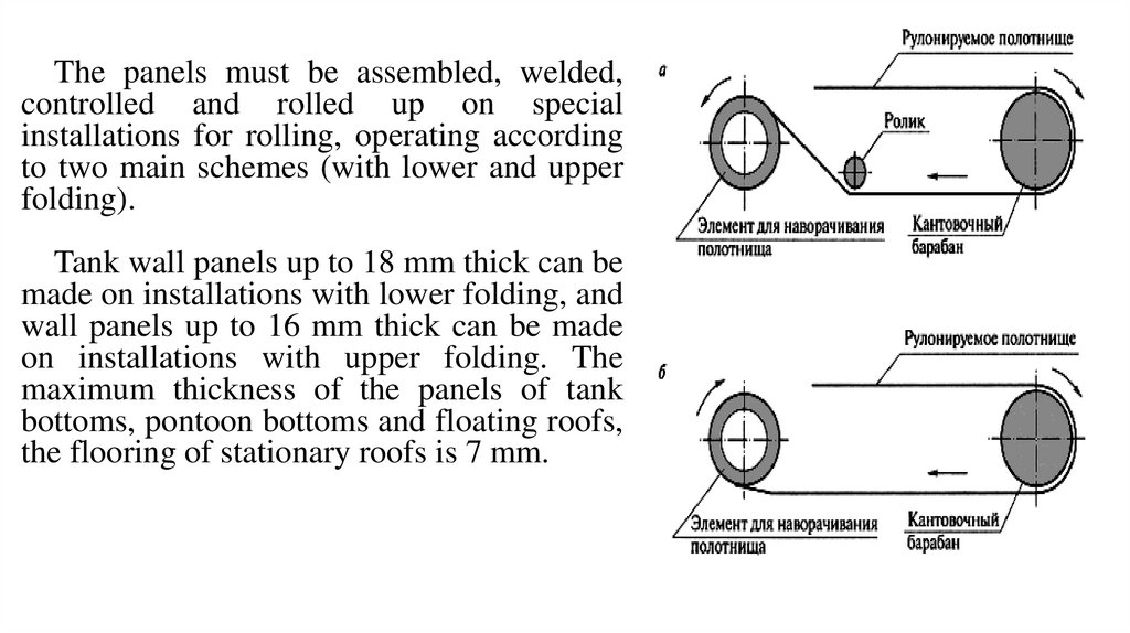
The panels must be assembled, welded,controlled and rolled up on special
installations for rolling, operating according
to two main schemes (with lower and upper
folding).
Tank wall panels up to 18 mm thick can be
made on installations with lower folding, and
wall panels up to 16 mm thick can be made
on installations with upper folding. The
maximum thickness of the panels of tank
bottoms, pontoon bottoms and floating roofs,
the flooring of stationary roofs is 7 mm.
6.
TRANSPORTATIONRolled structures up to 12 m high are transported on
four-axle railway platforms with a lifting capacity of 60
tons (Fig. a)To transport rolls with a height of 18 m, it is
advisable to use coupling-type railway conveyors with a
lifting capacity of 120 tons (Fig. b)
Rolled structures with a height of 18 m can be
transported on a railway four-axle platform with a lifting
capacity of 60 tons with two platforms covering. In this
case, it is necessary to ensure the simultaneous dispatch
of several rolls, then each cover platform overlaps the
ends of two rolls (Fig. b)
1 - self-propelled crane; 2 - unloading traverse; 3 - roll
marking place; 4 - four-axle railway platform;5 - roll; 6 cover platform; 7 - coupling conveyor; 8 - fixed bed; 9 movable bed
7.
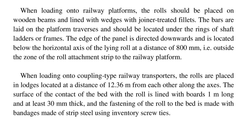
When loading onto railway platforms, the rolls should be placed onwooden beams and lined with wedges with joiner-treated fillets. The bars are
laid on the platform traverses and should be located under the rings of shaft
ladders or frames. The edge of the panel is directed downwards and is located
below the horizontal axis of the lying roll at a distance of 800 mm, i.e. outside
the zone of the roll attachment strip to the railway platform.
When loading onto coupling-type railway transporters, the rolls are placed
in lodges located at a distance of 12.36 m from each other along the axes. The
surface of the contact of the bed with the roll is lined with boards 1 m long
and at least 30 mm thick, and the fastening of the roll to the bed is made with
bandages made of strip steel using inventory screw ties.
8.
Elements of tank structures (coating shields, elements of stiffening rings and supportrings, boxes of pontoons and floating roofs, etc.) are transported on railway platforms and in
gondola cars in special containers or without them and fixed by methods and means that
exclude their deformation.
The mounting marking of structures must contain the factory order number and the
symbol of the mounting element in accordance with the mounting diagram in the working
drawings.
The mounting marking must be applied to the mounting elements in the places indicated
in the working drawings. The mounting marking of the rolled elements should be applied on
a label attached at the end of the roll to the element for wrapping, or applied with indelible
paint in two diametrically opposite places on the inner or outer surface of the roll at a
distance of no more than 500 mm from the end of the roll.
The mounting marking of elements of the same brand, fastened in a package, is allowed
to be applied only on the extreme elements, while the number of elements in the package
must be indicated.
9.
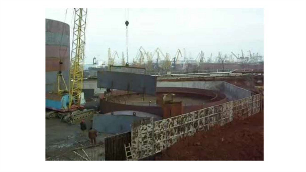
INSTALLATION OF THE BOTTOM AND THE CENTRAL PART OF THEFLOATING ROOF (PONTOON)
Installation of the bottom, consisting of the
central rolled part and the edges, is carried out in
the following sequence:
1) they are placed in the design position of the
paintwork, controlling the correctness of their
laying with the help of a marking device fixed in
the center of the base. When installing tanks
with a volume of more than 20,000 m3, the paint
should be laid along a radius exceeding the
design one by the shrinkage value of the ring of
the paint after welding (10 — 15 mm), which
should be provided for by the PP.
At the end of the assembly of the ring of the edges, it
is necessary to check:
the absence of fractures in the joints of the edges;
absence of deflections and bulges;
horizontality of the color ring;
compliance of gaps in joints with design
requirements;
10.
2) grab the assembled ring of nuts and weld the radial joints, If there is a crane with the required liftingobserving the requirements of the PR and VSN;
capacity on the mounting platform, the roll
of the bottom is laid on the base by a crane
3) roll the bottom rolls onto the base along a specially arranged ramp using a traverse.
in one of the following ways:
tractors, using devices fixed to the ends of the roll;by means of a The construction of the ramp must ensure
rope covering the roll, the ends of which are fixed to tractors (tractor the preservation of the shape of the base
and the concrete ring during the rolling of
winches).
the rolls.
Deployment of tank
bottom rolls with a
special device
1 — tractor;
2 — ramp;
3 — attachment;
4 — bottom roll
11.
If the traction force of the tractor (tractor winch)is not enough when rolling the rolls, then a
polispast should be applied;
4) unfold the bottom rolls taking into account the
least rolling of the rolls on one section of the base
and then moving the unfolded panels to the design
position, observing the following sequence:
set the roll to its original position for
deployment and cut the retaining strips;
• unfolding the outer panel, move it to a position
close to the design. The rest of the panels are
deployed in the same way;
• install the central panel in the design position.
5) weld the bottom in accordance with the requirements of the
PPM (Plan Preventive Maintenance). Before welding, it is
necessary to check: compliance with the dimensions of the
bottom with the design; compliance with the dimensions in the
overlapping joints, especially in places of double overlap; the
location of the edges provided for by the project relative to the
middle part of the bottom; the correct placement and cleaning
of the tacks.
1 — initial position of the bottom roll;
2 — ramp;
3 — unfolded panel;
4 — tractor
12.
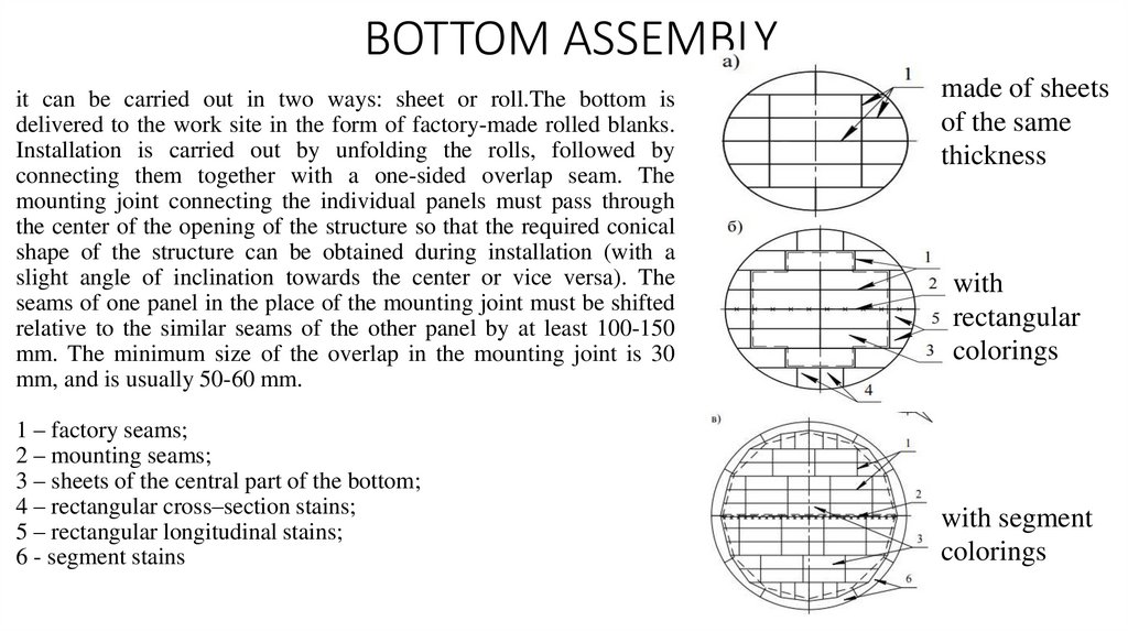
BOTTOM ASSEMBLYit can be carried out in two ways: sheet or roll.The bottom is
delivered to the work site in the form of factory-made rolled blanks.
Installation is carried out by unfolding the rolls, followed by
connecting them together with a one-sided overlap seam. The
mounting joint connecting the individual panels must pass through
the center of the opening of the structure so that the required conical
shape of the structure can be obtained during installation (with a
slight angle of inclination towards the center or vice versa). The
seams of one panel in the place of the mounting joint must be shifted
relative to the similar seams of the other panel by at least 100-150
mm. The minimum size of the overlap in the mounting joint is 30
mm, and is usually 50-60 mm.
1 – factory seams;
2 – mounting seams;
3 – sheets of the central part of the bottom;
4 – rectangular cross–section stains;
5 – rectangular longitudinal stains;
6 - segment stains
made of sheets
of the same
thickness
with
rectangular
colorings
with segment
colorings
13.
INSTALLATION SEQUENCEBottom deployment by two
tractors
Installation of the central
mounting stand by crane
Lifting the wall rolls with a
crane and a pipelayer
Deployment of wall rolls using
a pipelayer with simultaneous
installation of roof panels by
crane
Unfolding the wall roll
14.
15.
INSTALLATION OF THE VST WALLIn most cases, the cylindrical wall is
assembled from individual sheets measuring
6000 × 1500 mm (5990 × 1490 mm after the
edges are edged). Other parameters of
6000×2000 mm, 8000×2000 mm wall sheets
are also possible. The position of the sheets in
the wall is taken in such a way that the long
side of each individual sheet is directed
horizontally.
Horizontal rows of wall sheets are called
belts. Each individual belt consists of sheets of
the same thickness. The thickness of the belts is
determined by calculation and, as a rule,
increases from the upper belts to the lower ones
(corresponding to the law of hydrostatic
pressure distribution)
All the connections of the sheets in the belt are
made butt-to-butt. The belts can be connected
to each other butt-to-butt or overlap in a
telescopic or stepwise order
16.
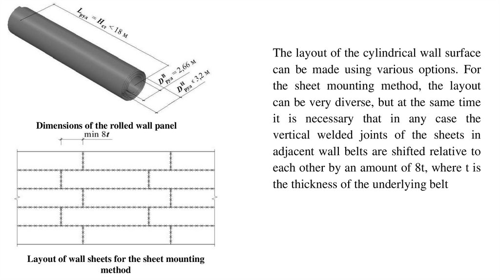
Installation of a cylindrical wall can be carried out in twoways: sheet or roll. The maximum thickness of the rolled
sheets is limited to 16-18 mm.The width of the wall panel
is limited to 18 m according to the manufacturing
conditions on the roll equipment. The length of the panel
should be no more than 66 m under the conditions of
transportation by rail (the outer diameter of the panel
wrapped on the frame, taking into account the permissible
looseness of the winding, should be no more than 3.2 m),
and the total weight of one roll is up to 60 tons. The
difference in the thickness of adjacent sheets should be no
more than 2 mm under welding conditions without beveling
the edges of the sheets.
17.
Dimensions of the rolled wall panelLayout of wall sheets for the sheet mounting
method
The layout of the cylindrical wall surface
can be made using various options. For
the sheet mounting method, the layout
can be very diverse, but at the same time
it is necessary that in any case the
vertical welded joints of the sheets in
adjacent wall belts are shifted relative to
each other by an amount of 8t, where t is
the thickness of the underlying belt
18.
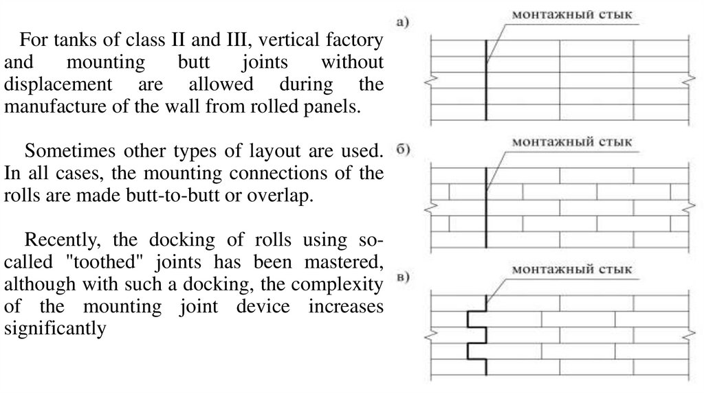
For tanks of class II and III, vertical factoryand
mounting
butt
joints
without
displacement are allowed during the
manufacture of the wall from rolled panels.
Sometimes other types of layout are used.
In all cases, the mounting connections of the
rolls are made butt-to-butt or overlap.
Recently, the docking of rolls using socalled "toothed" joints has been mastered,
although with such a docking, the complexity
of the mounting joint device increases
significantly
19.
INSTALLATION OF VERTICAL SEAM,WALL CLOSURE
Before closing the mounting joints of the
unfolded panels, the walls form the ends of
the panels that have significant residual
deformations from rolling. As a rule, wall
panels with a thickness of 8 mm or more are
formed. Shaping is carried out by a tractor
with the help of special devices. In the case
when it is required to form one or two belts of
the wall panel, it is recommended to use a
bending sector as a device
1 — wall roll;
2 — crane;
3 — bending sector;
4 — shaped section of the panel;
5 — traction rope;
6 — tractor
20.
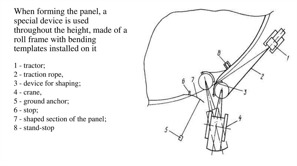
When forming the panel, aspecial device is used
throughout the height, made of a
roll frame with bending
templates installed on it
1 - tractor;
2 - traction rope,
3 - device for shaping;
4 - crane,
5 - ground anchor;
6 - stop;
7 - shaped section of the panel;
8 - stand-stop
21.
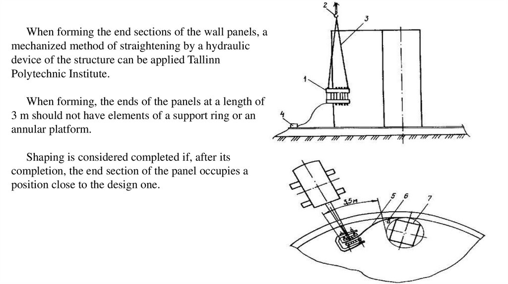
When forming the end sections of the wall panels, amechanized method of straightening by a hydraulic
device of the structure can be applied Tallinn
Polytechnic Institute.
When forming, the ends of the panels at a length of
3 m should not have elements of a support ring or an
annular platform.
Shaping is considered completed if, after its
completion, the end section of the panel occupies a
position close to the design one.
22.
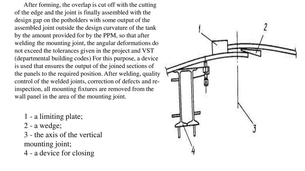
After forming, the overlap is cut off with the cuttingof the edge and the joint is finally assembled with the
design gap on the potholders with some output of the
assembled joint outside the design curvature of the tank
by the amount provided for by the PPM, so that after
welding the mounting joint, the angular deformations do
not exceed the tolerances given in the project and VST
(departmental building codes) For this purpose, a device
is used that ensures the output of the joined sections of
the panels to the required position. After welding, quality
control of the welded joints, correction of defects and reinspection, all mounting fixtures are removed from the
wall panel in the area of the mounting joint.
1 - a limiting plate;
2 - a wedge;
3 - the axis of the vertical
mounting joint;
4 - a device for closing
23.
INSTALLATION OF THE ROOF. SEQUENCE.STAGES
Low pressure tanks with a fixed roof, depending on the coating design, can
be:
- with a frame roof, with or without a central pillar (conical or spherical);
- with a frameless roof and a central rack (hanging, "momentary roof").
Stationary roofs are supported on the tank wall (on the annular element of
rigidity) and the central rack, or only on the wall (spacer system). For a
spherical roof, only a spacer structure is used.
The frameless roof is used for small snow loads (up to 1.5 kN/m2) and small
volumes (up to 5000 m3)
24.
THE METHOD OF SHEET ASSEMBLYAs a rule, tanks with a volume of up to
20,000 m3 are manufactured by the method of
sheet assembly. It is a manufacturing - rolling
of the bottom, walls, roofs of sheets, without
first welding them together. Individual sheets
are delivered to the construction site, where
the sheet assembly of the VST elements is
fully carried out. In addition to sheet assembly
and roll assembly of tanks, there is a method
of building up and lifting belts on jacks.
25.
26.
METHODS OF INSTALLATION WELDING OF TANKS- mechanized arc welding with a melting electrode in carbon dioxide shielding gas;
- automatic arc welding with a melting electrode under the flux;
- automated welding with forced seam formation with powder or activated wire.
- mechanized arc welding with self-protective powder wire;
- mechanized arc welding with self-protective powder wire in a protective gas environment;
- manual arc welding.
When welding in winter, it is necessary to systematically control the temperature of the metal
and, if the calculated cooling rate of the weld metal exceeds the permissible value for this steel
grade, it is necessary to organize preliminary, accompanying or post-welding heating of the
edges to be welded. The required temperature and the heating scheme must be defined in the
PPR. When heating the edges, the metal should be heated to the full thickness on both sides of
the joint to a width of 100 mm. The heating temperature control should be carried out with
thermal paints, thermal pencils, contact thermocouple thermometer, optical pyrometer. When
welding in winter, regardless of the air temperature and steel grade, the edges to be welded must
be dried from moisture.
27.
QUALITY CONTROL OF THE ASSEMBLY OF STRUCTURESTypes of quality control of welded joints:
mechanical testing of welded joints of witness samples;
visual inspection of all welded joints of the tank;
measuring control using templates, rulers, plumb lines, geodetic instruments,
etc.;
control of tightness (impermeability) of welds using samples of "chalkkerosene", vacuum chambers, excess air pressure or color flaw detection;physical methods
to detect the presence of internal defects: radiography or ultrasonic flaw
detection, and to control the presence of surface defects with a small opening
magnetography or color flaw detection;
hydraulic and pneumatic strength tests of the tank structure.