


 Медицина
Похожие презентации:


The final impression
1.
2.
THE FINAL IMPRESSIONThe final impression is made after the different steps of
mouth preparation .
Impression techniques might be different according to
the Functional Design Classification which is either:
1. Tooth Borne Partial Dentures.
2. Extension Base Partial Dentures.
3.
Factors influencing support of the distalextension base:
1. Contour and quality of the residual ridge:
-
The best foundation to give denture support is provided by:
The mandibular ridge :
- the crest of the mandibular ridge is formed from cancellous
bone it is not considered a primary stress bearing area.
On the other hand, the buccal shelf of bone is better suited
as a primary stress bearing area.
4.
The maxillary ridge :- cancellous bone, covered by soft tissue that is firm,
dense in nature. Thus, the crystal area may be a primary
stress bearing area .
- Buccal and lingual slopes of the ridge may offer more
resistance to vertical forces .
5.
2- The extent of residual ridge coverage:- The broader the coverage, the greater the
distribution of load/ per unit area.
6.
3. Design of RPD:- In distal extension bases, rotation around the most
posterior retainer under functional loading can be
controlling by use of an indirect retainer placed
anterior to the fulcrum line .
indirect retainer:
-
The indirect retainer more anteriorly and in the center to
the fulcrum line, more support the denture base.
7.
4. The total occlusal load applied:The amount of the occlusal force applied to a denture
base on a distal extension ridge influences the amount
of support required to stabilize the denture.
8.
The support may be improvedthrough:
• Maximum coverage of the ridge.
• Narrowing the occlusal table of the artificial teeth .
• Increasing the efficiency of artificial teeth by
supplemental grooves , increase the cutting action &
reduce the force required in chewing & less force will be
transmitted to the ridge.
9.
5. Accuracy of fit of the denture base:Support is enhanced by the intimacy of contact of the
tissues that cover the residual ridge.
6. Accuracy of impression registration:
Accurate impression making will ensure the construction
of a RPD that will accurately fit the underlying structures
and improve support.
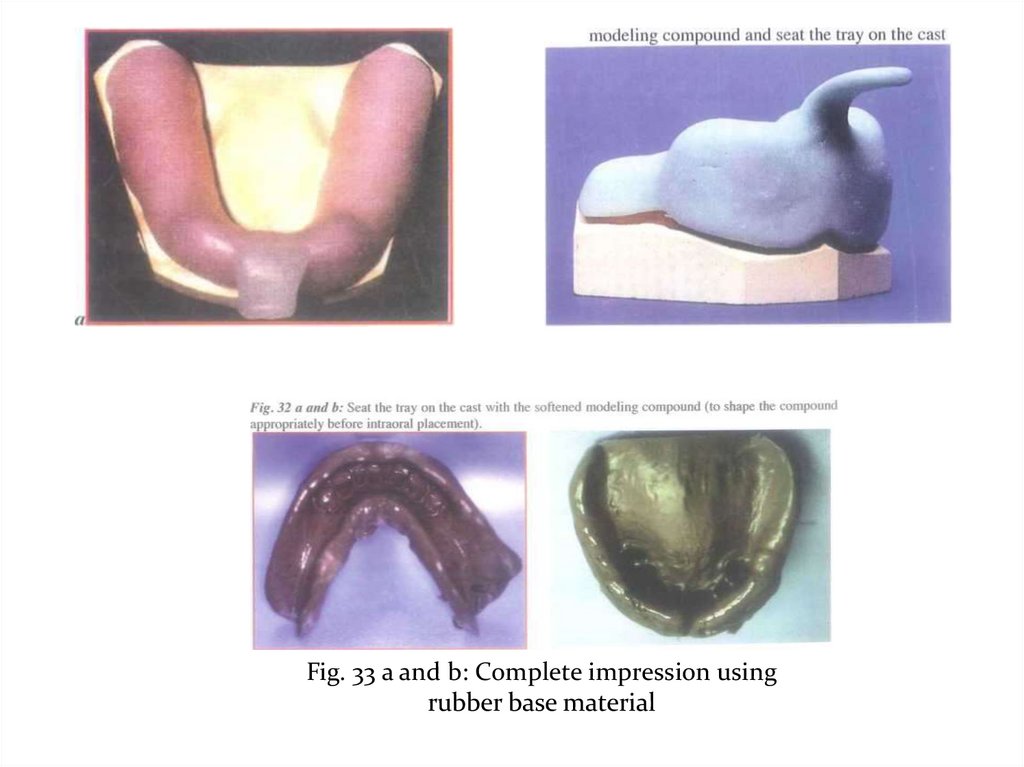
10.
Objectives of impression in Extension Base of R.P.D:1- Maximum coverage of the tissue available within the
physiologic limit.
2- Distributing the load widely over the largest possible area.
3- Fit the base to the edentulous ridge.
4- Direct the forces to the primary stress bearing areas.
5- Equalize the support derived from edentulous ridges and
abutment teeth to decrease torque on teeth and preserve bone.
6- Record the peripheries of the bases accurately.
11.
Types of impression techniques that can be used inpartial denture construction:
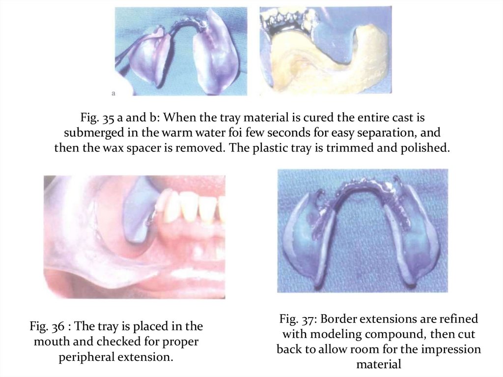
I- The anatomic form.
1- Using modified stock trays.
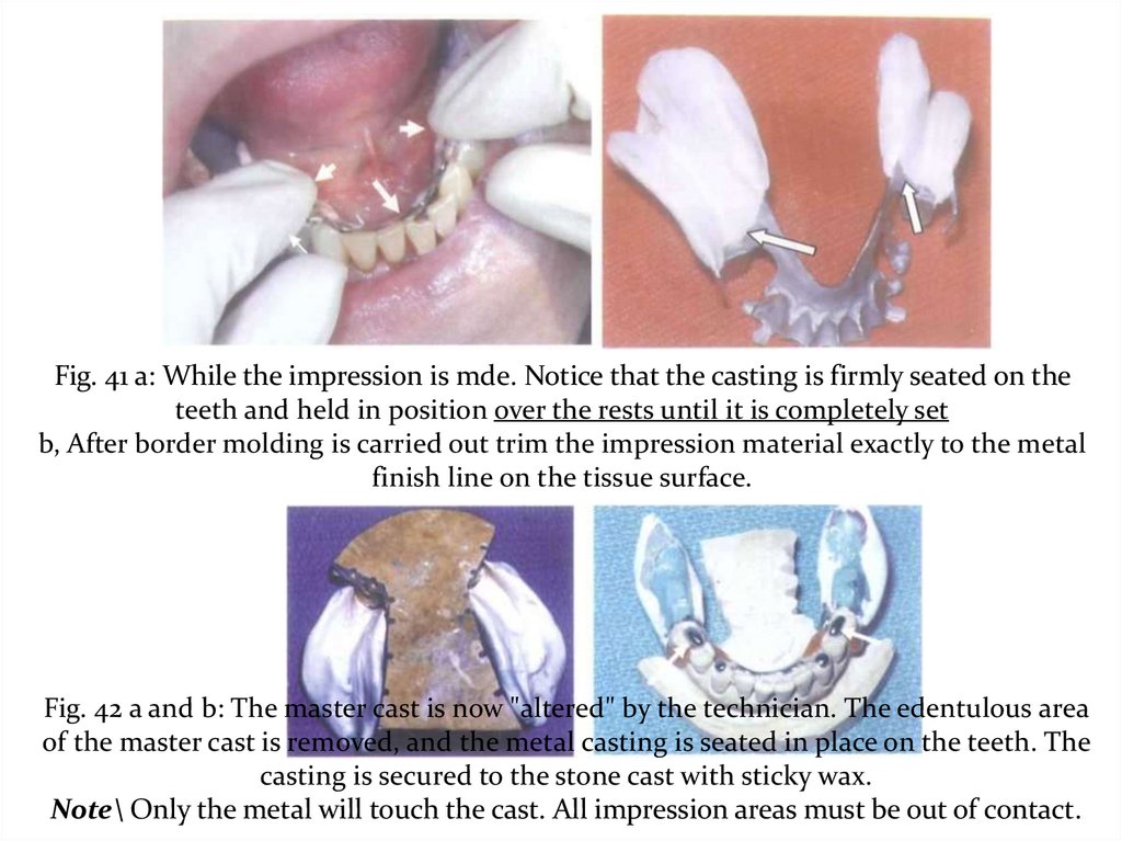
2- Using a custom trays.
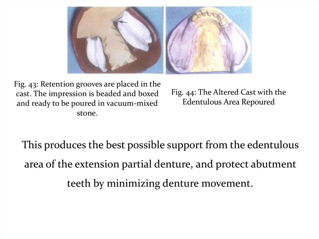
12.
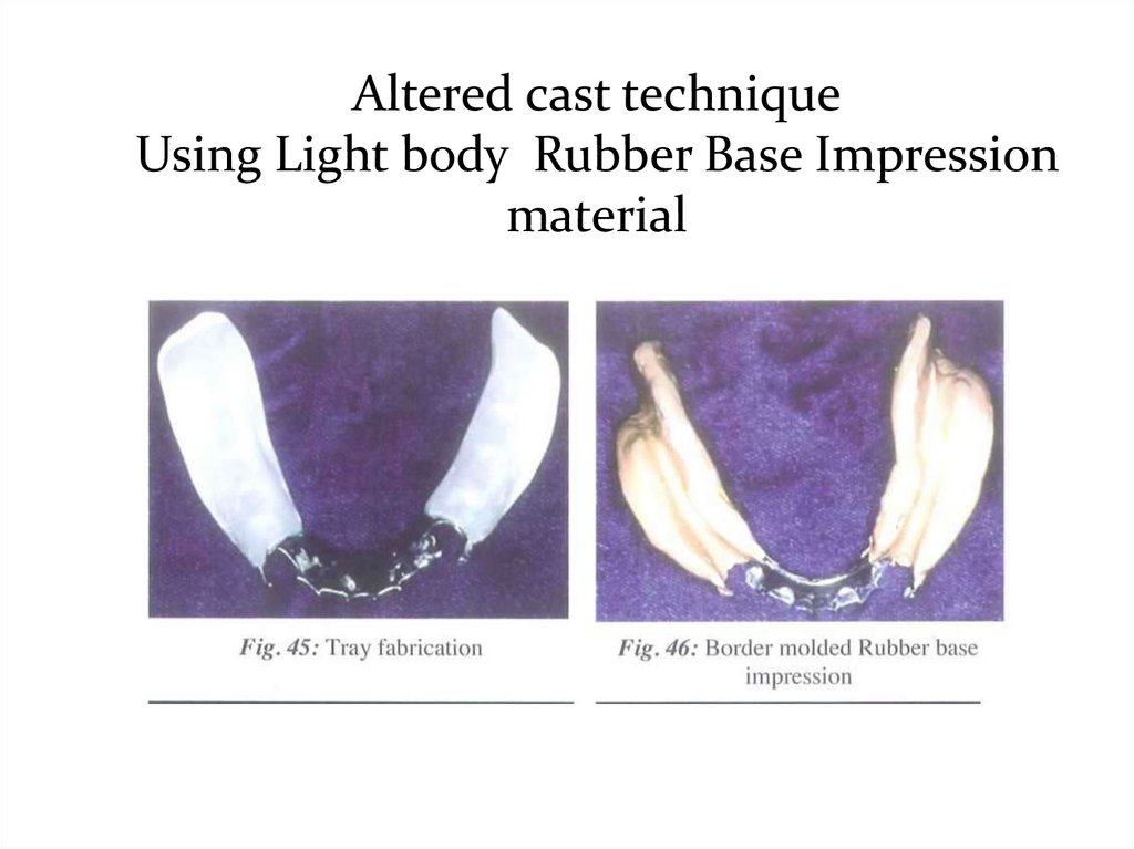
II. The physiologic or the functional form.1- At the impression stage:
- Mclean’s and Hindel’s Methods.
- One stage selective pressure impression technique.
2- At the framework stage:
The selective tissue placement impression technique.
(Altered cast technique)
3- At the finished denture stage.
The functional reline techniques using zn o or rubber base
impression material:
a- Old denture.
b- New denture.
13.
Preparation for ImpressionsAll mouth and tooth preparations must be completed prior
to final impressions.
1- Instructions to patient:
• Relax lips, tongue, and cheeks
• Advise patient that you will ask them to lift their tongue
• Ask patient to concentrate on breathing.
• Review the procedure with the patient.
2- Block out large embrasures and inter-proximal spaces:
to prevent tearing of the impression material on removal.
3- Dry teeth Pack arch with gauze.
14.
I-The anatomic form impression:-
It is mostly used in tooth supported RPD cases.
It is a one-stage impression, made using an elastic
impression material.
-
The cast produced represents the hard and soft tissues at rest.
-
It does not represent a functional relation between the various
supporting structures of the partially edentulous mouth.
- In cases of totally tooth supported partial denture cases, the
occlusal forces are transmitted towards the long axis of the abutment
teeth through occlusal, lingual or incisal rests.
15.
The anatomic form impression technique isperformed either by:
1 -Using modified stock trays with modeling compound or
wax ' - Alginate impression material.
Or,
2-Fabricate Custom trays on the diagnostic models
- Alginate impression material.
- Rubber base impression material.
16.
1- Modified Stock Tray Technique-
It is a standard technique for 95% of RPD
Impressions.
-
Ideal stock tray technique includes some
“customization” with periphery wax.
-
Custom trays are only needed for the unique patient
that a stock tray can’t be found that will cover the
necessary structures.
17.
Procedure for making theimpression:
- Select the suitable stock trays that should be adapted,
fitted and well extended.
- The size of tray is selected so that the teeth sit centrally
within the trough of the tray.
- Modify the tray with impression compound, pink wax
or auto polymerizing acrylic as appropriate, to improve
adaptation and extension of the tray.
- The impression procedure is made in the similar manner
as described previously for the preliminary impression
using the modified stock tray.
18.
Fig. 1 a and b: The size of tray is selected so that the teeth arecentrally located within the trough of the tray.
Fig. 3 .'Beading or periphery wax to improve
adaptation.
19.
2. Impression using custom trays:a- Alginate impression with Custom Trays.
b- Rubber base with Custom Trays.
20.
a) Construction of the special tray:-
On the study cast, base plate wax spacer is adapted on the
teeth and residual ridges to create space between the teeth and
the tray to make room for the impression material To
maintain a uniform thickness for the impression material
and to help accurate seating of the tray in the patient’s mouth,
wax stops are used.
-
The stops are mostly seated in the edentulous ridges
posteriorly and on the incisal edges anteriorly.
-
The thickness of the wax spacer depends on the impression
material that will be used
( 2mm for rubber and silicone and 4-6mm for alginate ).
21.
-The monomer and polymer are mixed according to the
manufacturer’s directions .
-
To have adequate and uniform thickness of the acrylic resin
dough it can be spread between two wet glass plates to the
desired thickness then adapted gently on the study cast.
-
While still soft the material should be trimmed to the
desired outline. With the excess material, the handle is
formed and attached to the tray.
-
The impression material may be retained to the tray either
by holes ( a no. 8 round bur ) or by adhesive spray.
22.
b)Making the impression:
After all the steps of mouth and abutment teeth
preparation are completed,
the impression procedure is made in the similar manner as
described previously for the preliminary impression using
the special tray.
23.
N.B:• No bubbles should be around or in rest preparations.
• No bubbles should be in the palate where major connectors
are to be constructed.
• There should be no tearing of the impression material
where the teeth are involved in the design .
• The tray should not be showing through the cusp tips.
24.
- After checking the impression and its approval, theimpression is poured with stone plaster and the master cast is
obtained.
- On the master cast the different steps for metal framework
construction and the completion of the RPD are carried out.
25.
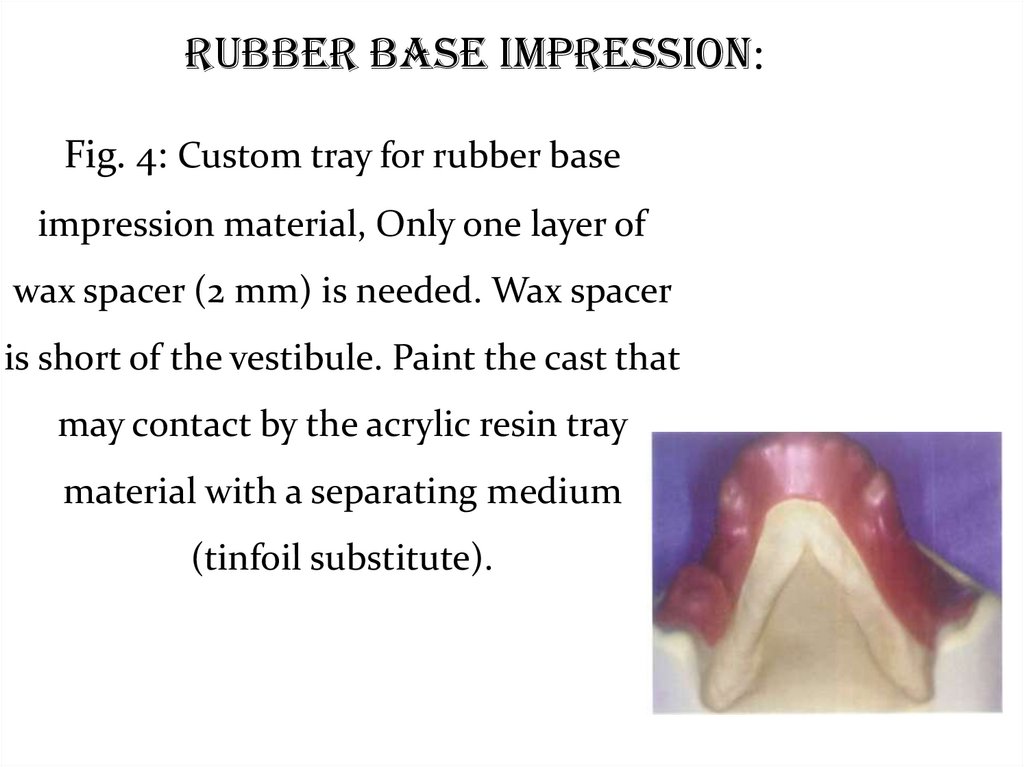
Rubber Base Impression:Fig. 4: Custom tray for rubber base
impression material, Only one layer of
wax spacer (2 mm) is needed. Wax spacer
is short of the vestibule. Paint the cast that
may contact by the acrylic resin tray
material with a separating medium
(tinfoil substitute).
26.
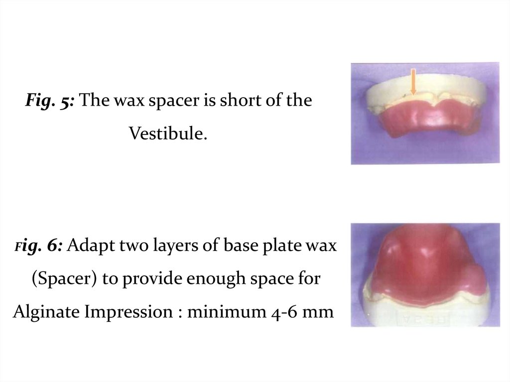
Fig. 5: The wax spacer is short of theVestibule.
Fig.
6: Adapt two layers of base plate wax
(Spacer) to provide enough space for
Alginate Impression : minimum 4-6 mm
27.
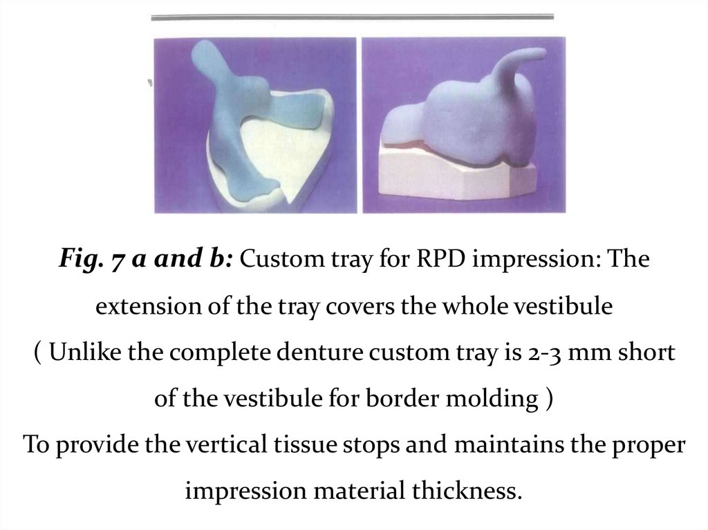
Fig. 7 a and b: Custom tray for RPD impression: Theextension of the tray covers the whole vestibule
( Unlike the complete denture custom tray is 2-3 mm short
of the vestibule for border molding )
To provide the vertical tissue stops and maintains the proper
impression material thickness.
28.
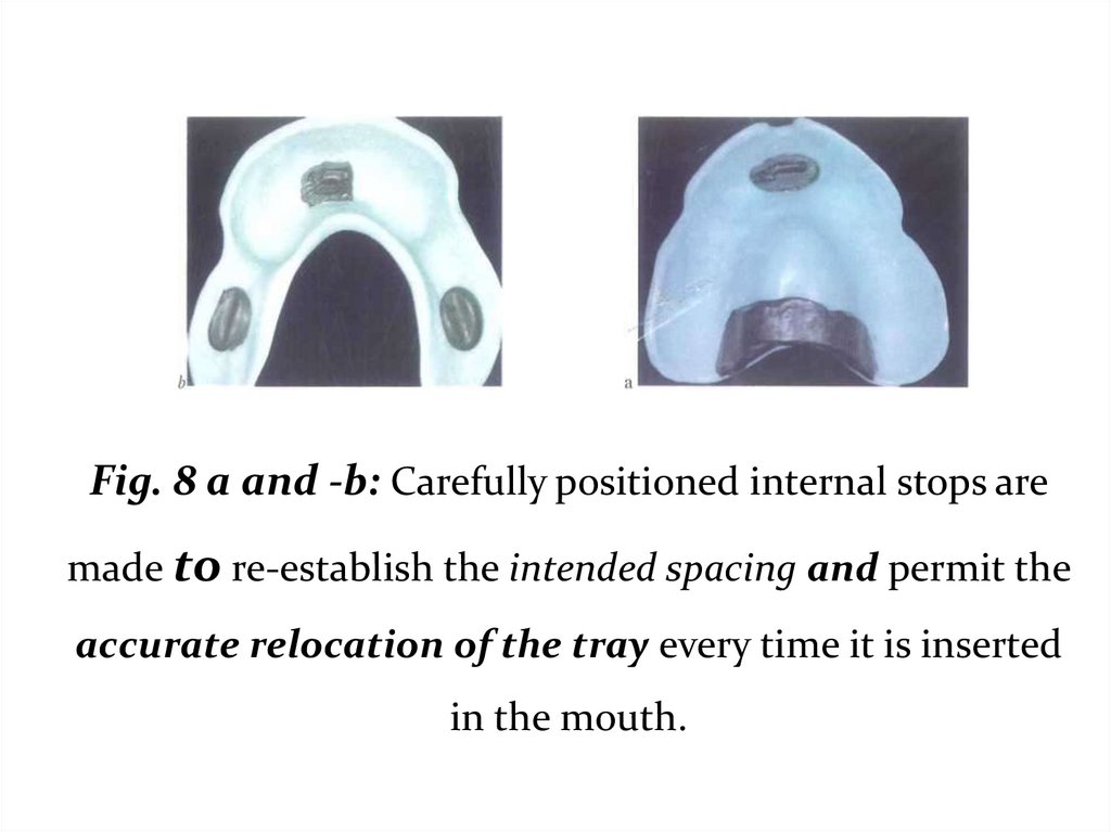
Fig. 8 a and -b: Carefully positioned internal stops aremade to re-establish the intended spacing and permit the
accurate relocation of the tray every time it is inserted
in the mouth.
29.
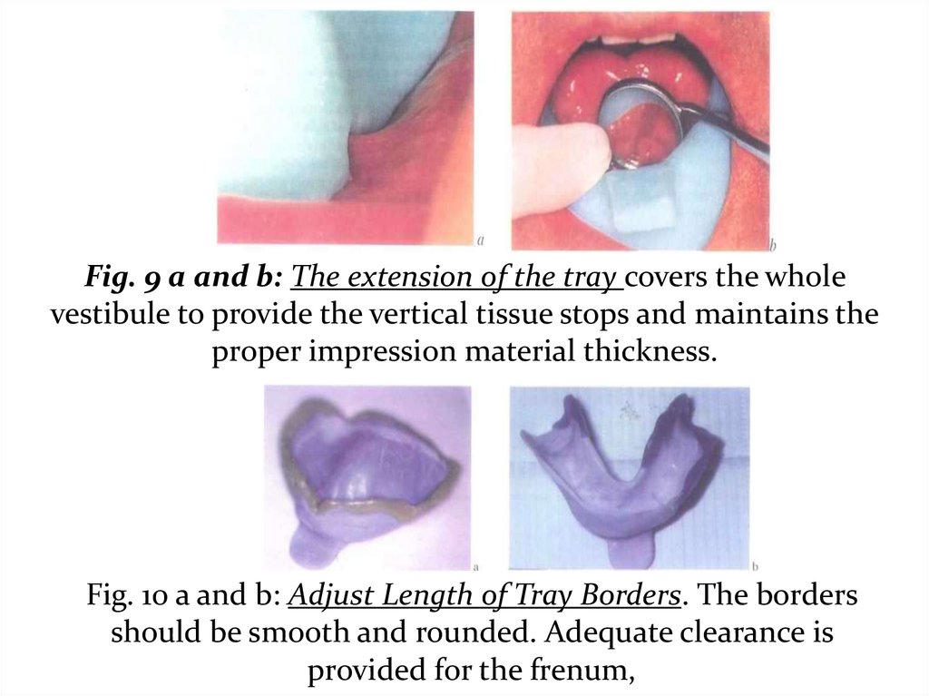
Fig. 9 a and b: The extension of the tray covers the wholevestibule to provide the vertical tissue stops and maintains the
proper impression material thickness.
Fig. 10 a and b: Adjust Length of Tray Borders. The borders
should be smooth and rounded. Adequate clearance is
provided for the frenum,
30.
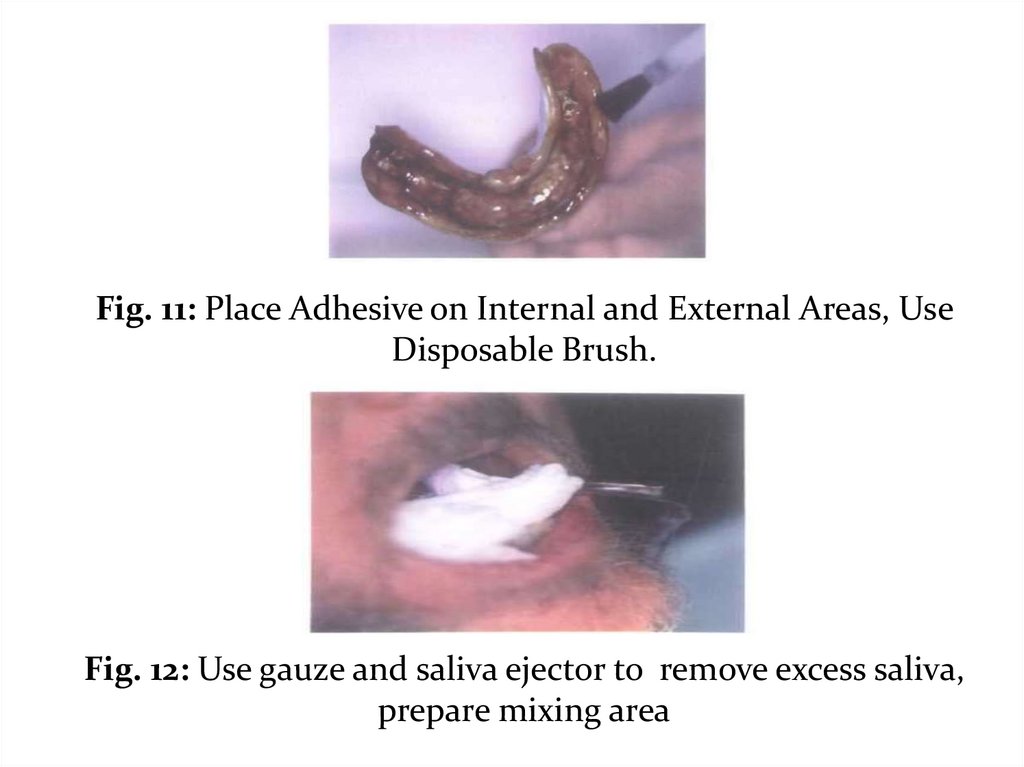
Fig. 11: Place Adhesive on Internal and External Areas, UseDisposable Brush.
Fig. 12: Use gauze and saliva ejector to remove excess saliva,
prepare mixing area
31.
Fig. 15 a and b:Mark Denture Base Extensions: The mark should be placed 3-4 mm
above the peripheral roll. Apply sticky wax to marked border.
32.
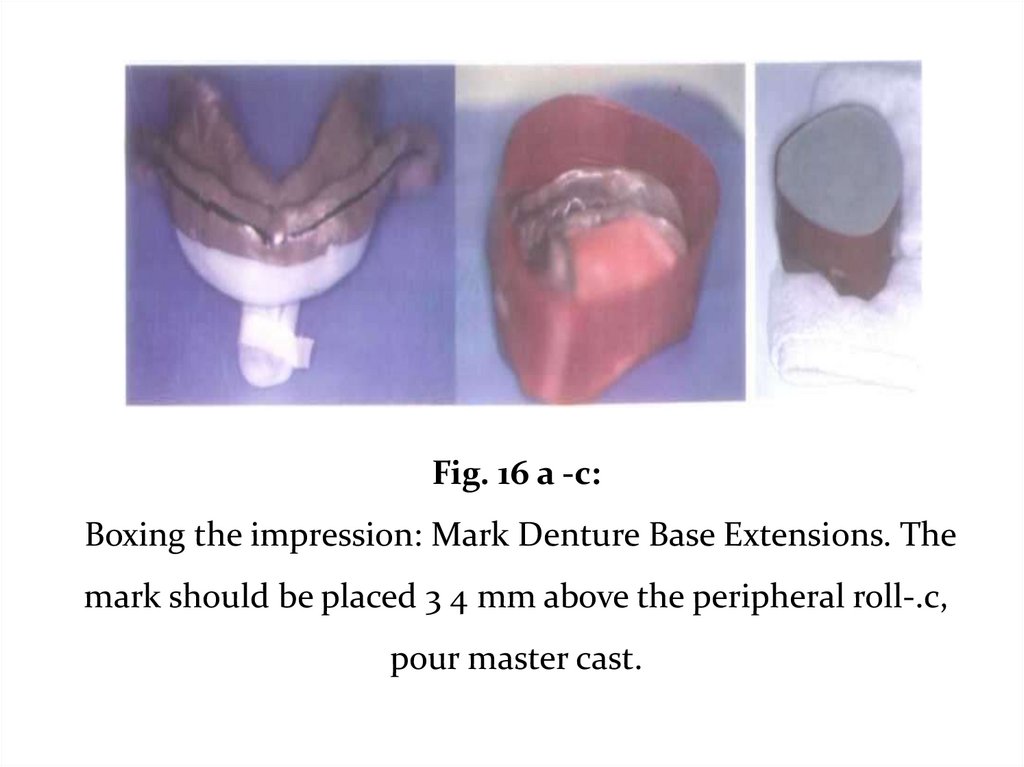
Fig. 16 a -c:Boxing the impression: Mark Denture Base Extensions. The
mark should be placed 3 4 mm above the peripheral roll-.c,
pour master cast.
33.
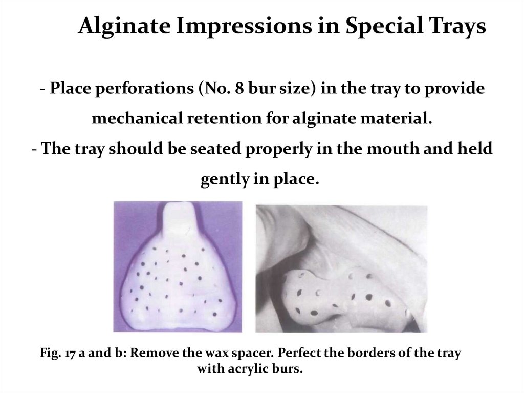
Alginate Impressions in Special Trays- Place perforations (No. 8 bur size) in the tray to provide
mechanical retention for alginate material.
- The tray should be seated properly in the mouth and held
gently in place.
Fig. 17 a and b: Remove the wax spacer. Perfect the borders of the tray
with acrylic burs.
34.
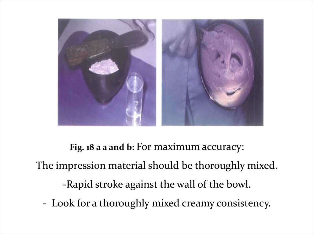
Fig. 18 a a and b: For maximum accuracy:The impression material should be thoroughly mixed.
-Rapid stroke against the wall of the bowl.
- Look for a thoroughly mixed creamy consistency.
35.
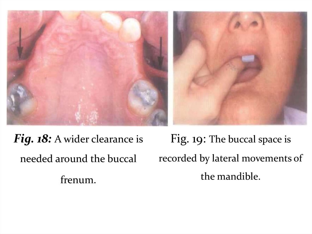
Fig. 18: A wider clearance isFig. 19: The buccal space is
needed around the buccal
recorded by lateral movements of
frenum.
the mandible.
36.
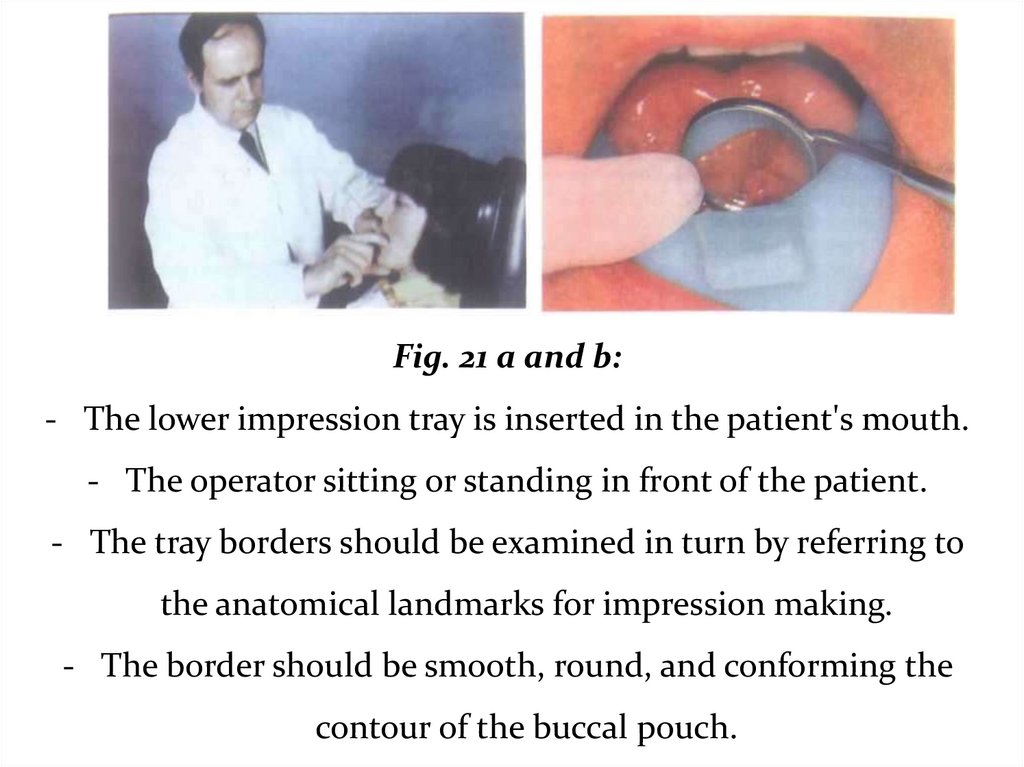
Fig. 21 a and b:- The lower impression tray is inserted in the patient's mouth.
- The operator sitting or standing in front of the patient.
- The tray borders should be examined in turn by referring to
the anatomical landmarks for impression making.
- The border should be smooth, round, and conforming the
contour of the buccal pouch.
37.
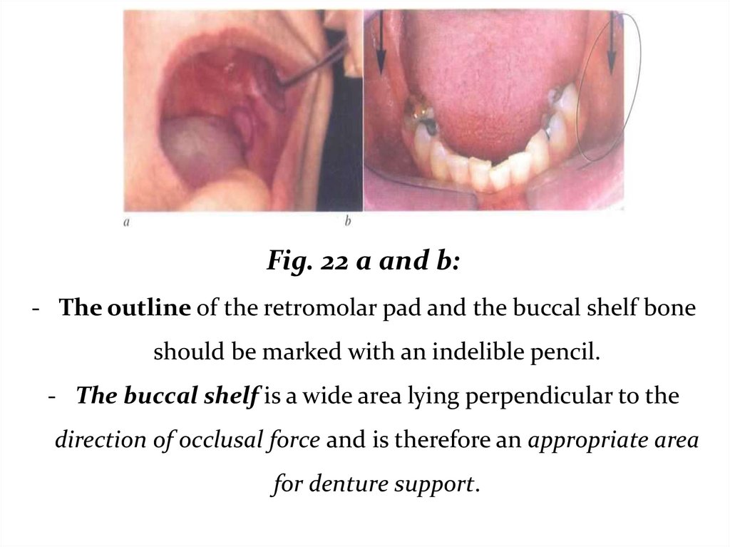
Fig. 22 a and b:- The outline of the retromolar pad and the buccal shelf bone
should be marked with an indelible pencil.
- The buccal shelf is a wide area lying perpendicular to the
direction of occlusal force and is therefore an appropriate area
for denture support.
38.
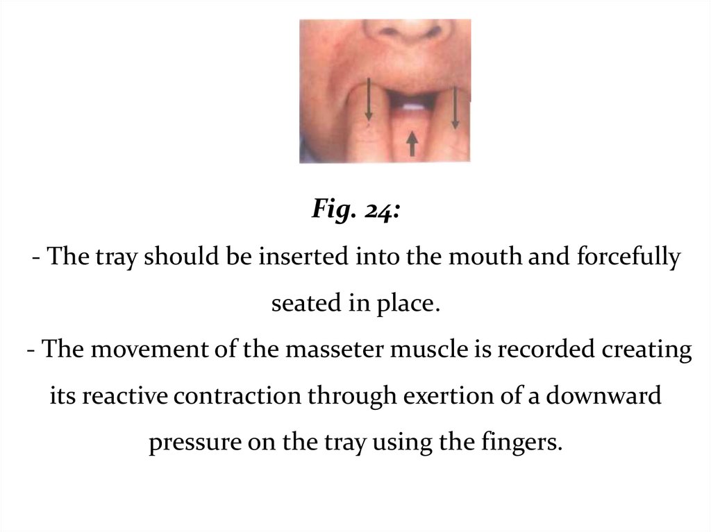
Fig. 24:- The tray should be inserted into the mouth and forcefully
seated in place.
- The movement of the masseter muscle is recorded creating
its reactive contraction through exertion of a downward
pressure on the tray using the fingers.
39.
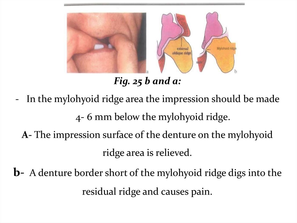
Fig. 25 b and a:- In the mylohyoid ridge area the impression should be made
4- 6 mm below the mylohyoid ridge.
A- The impression surface of the denture on the mylohyoid
ridge area is relieved.
b- A denture border short of the mylohyoid ridge digs into the
residual ridge and causes pain.
40.
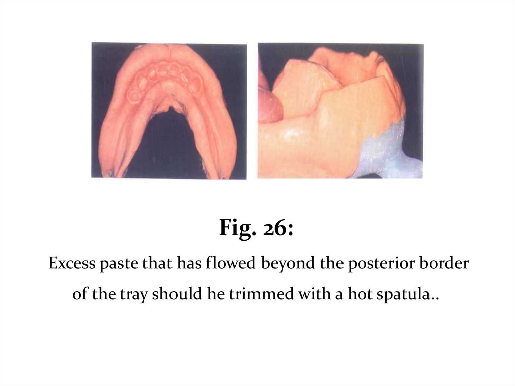
Fig. 26:Excess paste that has flowed beyond the posterior border
of the tray should he trimmed with a hot spatula..
41.
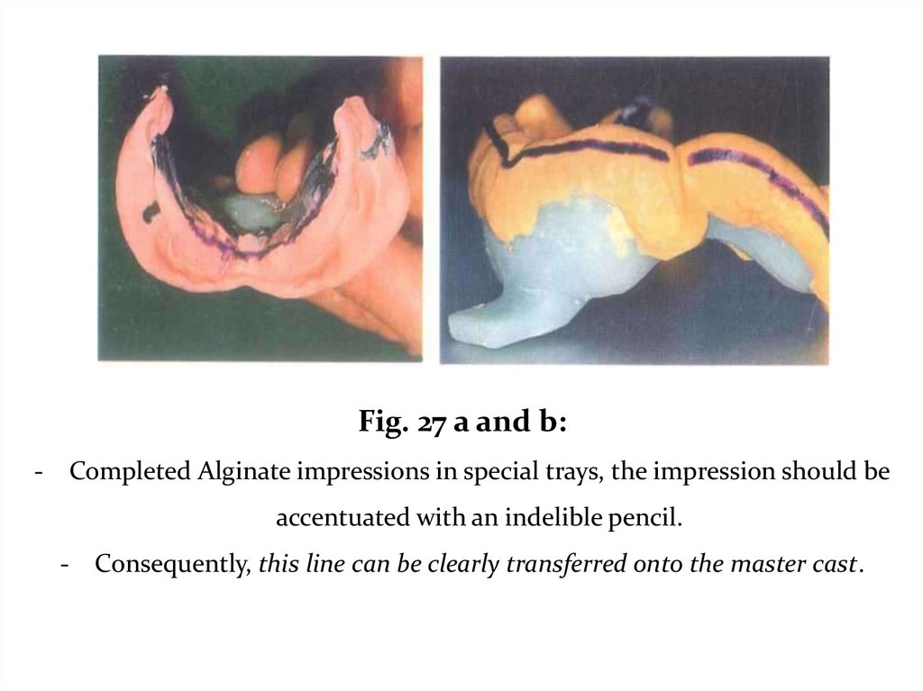
Fig. 27 a and b:- Completed Alginate impressions in special trays, the impression should be
accentuated with an indelible pencil.
- Consequently, this line can be clearly transferred onto the master cast.
42.
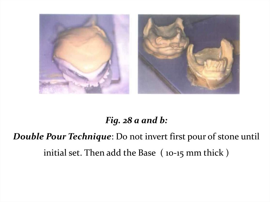
Fig. 28 a and b:Double Pour Technique: Do not invert first pour of stone until
initial set. Then add the Base ( 10-15 mm thick )
43.
Gagging: ?????o Thicker mix of Alginate.
o Mandibular impression: contact with tongue can be
unavoidable.
Proper fit of tray, shorten un-necessary areas .
o Maxillary impression: Bend head forward, causes lift of soft
palate.
Beading wax to reduce alginate posterior flow.
o Tell patient, please do not move your tongue
44.
Inspect the Impression ???????Carefully rinse the impression with tap water.
Failure to do so will result in a cast with a soft or chalky
surface.
Saliva can be identified on the cast by sprinkling stone
on the impression and gently rinsing it away with tap water.
Inspect areas that the framework contacts (rests, guide
planes, major/minor connector.
45.
• Inspect areas that the framework contacts (rests, guideplanes, major/minor connector.
• Before pouring the cast remove all moisture with a gentle
stream of air. Be careful not to over dry the impression.
• Disinfect the impression.
• Pour immediately!- Double Pour Technique
Never box an alginate impression with wax or a mixture
of plaster and pumice.
46.
Imbibition - distortion by water absorption.Svneresis - loss of water and shrinkage distortion.
Pouring of the alginate impression without making
boxing, but take care when pouring and trimming the cast to
ensure that the functional depth and width of the sulcus so
carefully is preserved. Pour within 10 minutes.
47.
Pour in vacuum mixed stone.■ Measure the required amounts of water and powder.
■ Carefully mix the stone in a vacuum power mixer
■ Using gentle vibration, flow the stone into the indentations
in the impression formed by the teeth.
• Use a small brush to avoid trapping air
48.
• The bottom surface of the cast should be rough tofacilitate attachment of the base:
■ poured impression by the handle in the tray holder.
■ Once the stone is fully set invert the cast and add a base. The
base should be 10-15 mm thick ( Provide adequate base
thickness ).
■ After 60 minutes of the first pour, separate the impression
from the cast .
49.
• Trimming should not begin until 24 hours after pouring.• Before trimming the cast soak it in clear water for 5 minutes
to sludge adhering to and damaging the cast.
• The cast should be trimmed so that its base is 10-15 mm thick.
• The land should be 4 mm wide.
• The cast should never be rinsed, or soaked in water
because dental stone is water-soluble.
50.
ProblemProbable cause
- Saliva in the impression when cast was
Surface of the cast soft or
poured
chalky
- Improper water powder ratio used
- Water from rinsing remains in impression
- Impression material separated from the
tray
Distorted cast
- Air inclusion in impression that distorts
when stone is poured
51.
Objectives of impression in distal extensions:• Provides maximum support, by distributing load on as large an
area as possible.
• Equalizes support derived from edentulous ridges and abutment
teeth.
• Directs forces to the primary stress bearing areas.
52.
For an impression technique to achieve thoseobjectives it must:
1.
Record and relate the supporting structures under some loading.
2.
3.
Distribute the load over the largest possible area.
Record the peripheries of the bases accurately.
A thorough understanding of the impression techniques and
materials is essential in RPD construction to provide
maximum support.
53.
II. The physiologic or the functional form impressiontechniques:
1- At the impression stage:
- Mclean’s and Hindel’s Methods.
- One stage selected pressure impression technique.
54.
- If a distal extension RPD were constructed from an anatomicimpression it would exert excessive pressure on the abutment teeth
during function.
- The main objective in an impression for distal extension is to
provide maximum support for the RPD, maintaining occlusal
contact to distribute the occlusal forces over the natural, and
artificial teeth and minimize movement of the base that may create
leverage on the abutment teeth.
- The philosophy of these techniques is to record the edentulous
ridges under some degree of loading ( functional pressure to have
functional form ) and the other supporting structures are recorded
during rest ( to have anatomic form ).
55.
Mclean’s and Hindel’s Methods.- These old techniques have several drawbacks as they
could not record exactly the functional displacement of
the tissues produced by the biting force. And they did not
eliminate the variable of the patients and dentist's
individual interpretation of the functional loading
magnitude.
56.
One stage selective pressure impression techniqueThe selective pressure impression technique helps to
equalize the support between the abutment teeth and the
residual ridge, and directs the force to the ridge areas that
are most capable of withstanding these forces i.e. the
primary stress bearing areas
Dumbrigue and Esquivel in 1998 described a technique
for the selective pressure impression technique from a
single impression made prior to framework construction
and after mouth preparation.
57.
Procedure:1. On the study cast a tray is constructed as follows:
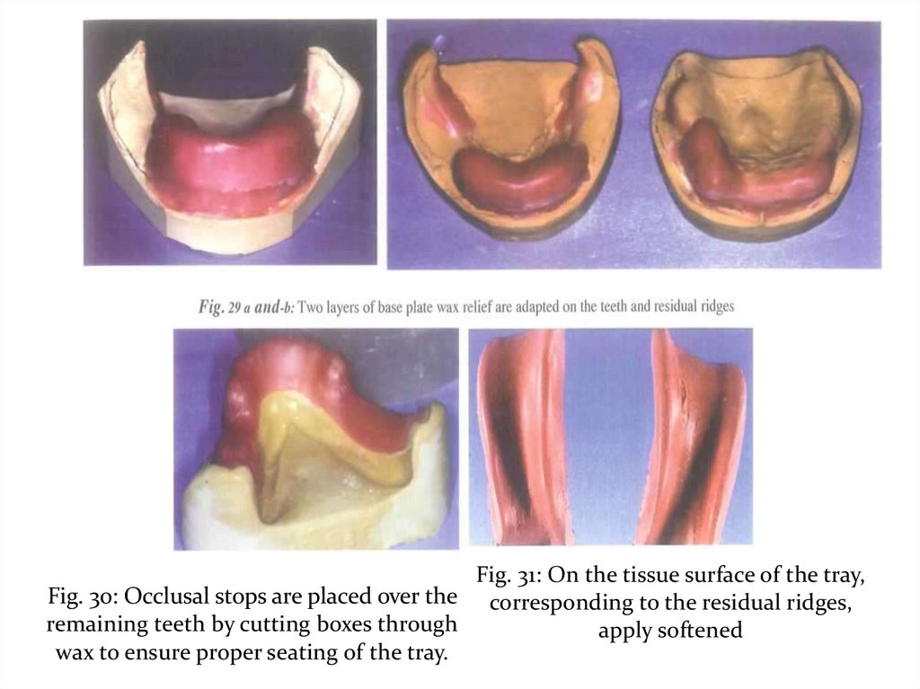
• Two layers of base plate wax relief are adapted on the teeth
and residual ridges. Aluminum foil is burnished over the wax.
• Occlusal stops are placed over the remaining teeth by cutting
boxes through the aluminum foil and wax to ensure proper
seating of the tray.
• Construct an acrylic resin special tray 2mm short of the
borders.
• Remove wax from the cast and wet the surface of the cast.
58.
2. On the tissue surface of the tray, corresponding to theresidual ridges, apply softened modeling compound and seat
the tray on the cast (to shape the compound appropriately
before intraoral placement).
3. Reheat compound and place intraorally with finger pressure
on the area of the residual ridge.
4. Remove, check and then apply modeling compound to the
borders to perfect border molding.
59.
5. Relief the tissue surface of the compound 1mm except forthe primary stress bearing area (buccal shelf of bone).
6. Make a complete impression using rubber base material
applying finger pressure on the residual ridge while the
impression material is setting.
Pour the impression and proceed the steps for constructing the
framework.
60.
Fig. 31: On the tissue surface of the tray,Fig. 30: Occlusal stops are placed over the corresponding to the residual ridges,
remaining teeth by cutting boxes through
apply softened
wax to ensure proper seating of the tray.
61.
Fig. 33 a and b: Complete impression usingrubber base material
62.
2- The functional impression technique at theframework stage:
The altered cast technique (The selective tissue placement
impression technique)
■ This selective pressure impression technique is made after
construction of the framework on a cast obtained from an
anatomic impression.
■ It is mainly used in mandibular class I and II cases.
63.
■ The framework is tried in the patient’s mouth, and adjustedto fit accurately on the supporting structures with the rests
properly seated on their seats and the indirect retainers in their
position.
■ The occlusion with the opposing dentition is also adjusted if
in need.
■ Areas that need relief e.g. internal oblique ridge if prominent
and top of the ridge (lower ridge) are relieved on the master
cast using wax.
■ The stress bearing areas (buccal shelf of bone) is left without
relief.
64.
■ An acrylic resin special tray is constructed on the ridge area,attached mechanically to the mesh of the framework (by
seating the framework properly over the cast while the acrylic
resin is still soft).
■ The framework with the tray attached to it is tried in the
patient’s mouth, making sure that the framework fits
accurately.
■ The borders are then shortened and border molded using
green stick compound.
65.
■ The trays are then loaded with the impression material andthe framework seated in the patient’s mouth. Be sure that the
occlusal rests and indirect retainers are properly seated and
maintained in position by the three fingers of the operator
(two on the main occlusal rests and one on the indirect
retainer) until complete setting of the impression material.
■ Different materials may be used for making the impression
as zinc oxide and eugenol and rubber base materials. Fluid wax
may also be used. Fluid waxes are waxes that are firm at room
temperature and have the ability to flow in mouth
temperatures ( Iowa wax no.l and Korrecta wax no. 4). Its
drawback is that it is time consuming as it is applied layer by
layer and needs some experience.
66.
■After the impression has been made and is accepted, the
distal extension areas on the master cast are sawed off or cut off
by means of a disc.
■ Two cut lines are done on each side, one horizontal distal to
the last abutment and the other nearly perpendicular to it in
the lingual sulcus.
■ Retentive grooves are then cut on the sides of the cast along
the cut off areas.
67.
■ The framework with the impression is reseated on the cast,making sure that the framework is perfectly seated in position
with no interference anywhere. Modeling plastic placed on the
rests and indirect retainers may aid in ensuring that no
movement of the framework occurs during pouring the new
impression of the edentulous ridges.
■
The impression is beaded, boxed and the edentulous
ridge is poured with stone preferably with a different color than
that of the original cast.
68.
Fig. 33 a and b: The casting which lias been adjusted is placed on themaster cast. A single layer of baseplate wax is placed over the edentulous
area to provide a space for the impression material.
Ensuring that all rests are well in place.
Fig. 34 a and b: Prepare the tray The purpose of the tray is to
carry a uniform thickness of the final impression material to the
mouth exerting reasonable pressure on the mucosa
69.
Fig. 35 a and b: When the tray material is cured the entire cast issubmerged in the warm water foi few seconds for easy separation, and
then the wax spacer is removed. The plastic tray is trimmed and polished.
Fig. 36 : The tray is placed in the
mouth and checked for proper
peripheral extension.
Fig. 37: Border extensions are refined
with modeling compound, then cut
back to allow room for the impression
material
70.
Fig. 38: Vent holes are placed inthe maxillary plastic tray near
the finish line for escape of
excess impression material.
Fig. 39: Vent holes are placed in
the mandibular plastic tray near
the finish line for escape of excess
impression material.
Fig. 40 a and b: Material is mixed, the tray is loaded, and Do not over load the
material! The casting is firmly seated on the teeth and held in position over the rests
until it is completely set. Do not allow
movement on the edentulous area!
71.
Fig. 41 a: While the impression is mde. Notice that the casting is firmly seated on theteeth and held in position over the rests until it is completely set
b, After border molding is carried out trim the impression material exactly to the metal
finish line on the tissue surface.
Fig. 42 a and b: The master cast is now "altered" by the technician. The edentulous area
of the master cast is removed, and the metal casting is seated in place on the teeth. The
casting is secured to the stone cast with sticky wax.
Note\ Only the metal will touch the cast. All impression areas must be out of contact.
72.
Fig. 43: Retention grooves are placed in thecast. The impression is beaded and boxed
and ready to be poured in vacuum-mixed
stone.
Fig. 44: The Altered Cast with the
Edentulous Area Repoured
This produces the best possible support from the edentulous
area of the extension partial denture, and protect abutment
teeth by minimizing denture movement.
73.
Altered cast techniqueUsing Light body Rubber Base Impression
material
74.
Fig. 47 a-c: The Altered Cast with the Edentulous Area Repoured This produces thebest possible support and orientation of the metal casting to the remaining teeth.
Effective preventive measure to protect abutment teeth by providing 2-3 times greater
mucosal support and minimizing denture movement.
75.
3- The functional reline techniques using zinc oxide andeugenol paste or rubber impression material at the
finished denture stage
The idea of this technique:
1 - For New Denture:
Used for a distal extension RPD constructed from single
anatomic impression to avoid movement on the edentulous
area after application of masticatory load that create torque on
the abutment teeth.
2- For Old Denture:
After denture use for a long time, a combination of occlusal
wear and sinking of the denture following alveolar resorption
occurs .So functional impression is required to improve the fit
of the PD to the underlying tissues.
76.
It is an open mouth procedure:1. The borders are shortened and the denture base is relieved
to allow room for the impression material.
2. Modeling plastic is applied over the tissue surface and
tempered in water bath, seated in the patient’s mouth and held
in position with 3 fingers, two on the main occlusal rests and
one on the indirect retainer. This is done several times until an
accurate impression of the ridges is obtained.
77.
3. The tissue surface is then scraped to about 1mm thickness. Amix of zinc oxide and eugenol material is then applied. The
denture is seated in the patient’s mouth and held in position
by the three fingers the same as before until complete setting
of the material.
Different impression materials may be used successfully, for
functional reline impression; zinc oxide and eugenol, rubber
base, silicones, mouth temperature waxes as well as tissue
conditioning material) provided that there is proper space and
border molding is carried out.
78.
4.An overall alginate impression is made and the whole
impression is poured. The denture on the obtained cast is
flasked and relining procedure is completed.
It is essential that occlusal errors are adjusted, so the relined
denture should be remounted.