


 Электроника
Похожие презентации:


PCB Recycling Component Level Repair Techniques
1.
Viera Plasma Display PC Board RecyclingComponent Level Repair
Course 2
PCB Recycling Component Level Repair Techniques
2.
Adjustments ProcedureThe following adjustment procedures are mandatory after replacing the
SC, SS & P boards. It is also required if the Panel is replaced.
I. Item preparation:
1. Input a white signal. (please refer to the next slide on several ways
to generate a white pattern).
2. Set picture controls as follows:
Picture menu: Dynamic
P-NR: OFF
Aspect: 16:9
CAUTION:
1.
Perform Vsus adjustment first.
2.
Confirmation of Vscn voltage should be done after confirmation of
Vad adjustment.
When Vad = -105V, Vscn voltage is 35V +/- 4V.
3.
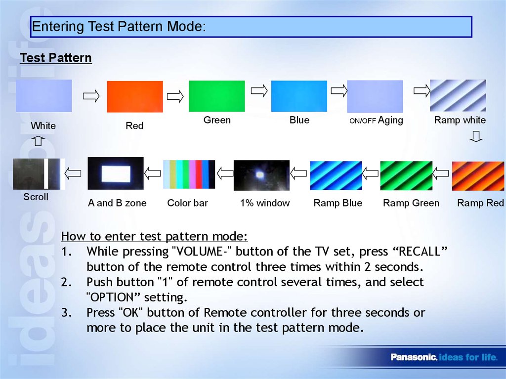
Several ways to generate White Pattern signal:1. External pattern generator.
2. Internal white pattern in Service mode.
(Please see next slide on how to enter Test Pattern Mode).
3. Disconnect LVDS cable DG5 on the DG board to display white
pattern.
4.
Entering Test Pattern Mode:Test Pattern
White
Scroll
Red
A and B zone
Green
Color bar
Blue
1% window
ON/OFF Aging
Ramp Blue
Ramp white
Ramp Green
How to enter test pattern mode:
1. While pressing "VOLUME-" button of the TV set, press “RECALL”
button of the remote control three times within 2 seconds.
2. Push button "1" of remote control several times, and select
"OPTION” setting.
3. Press "OK" button of Remote controller for three seconds or
more to place the unit in the test pattern mode.
Ramp Red
5.
II. Driver Adjustment TH42PX60Name
Test Point
Voltage
Volume
Remarks
Vsus
TPVSUS (SS)
Vsus ± 2V
VR251 (P)
*
Ve
TPVE (SS)
Ve ± 2V
VR6000 (SS)
*
Vset
TPVSET (SC)
280V ± 7V
Fixed
Vad
TPVAD (SC)
-105V ± 1V
VR6600 (SC)
Vscn
TPVSCN (SC)
Vad+140V ± 4V
Fixed
Vda
TPVDA (SS)
75V ± 1V
Fixed
Adjustment
voltage
6.
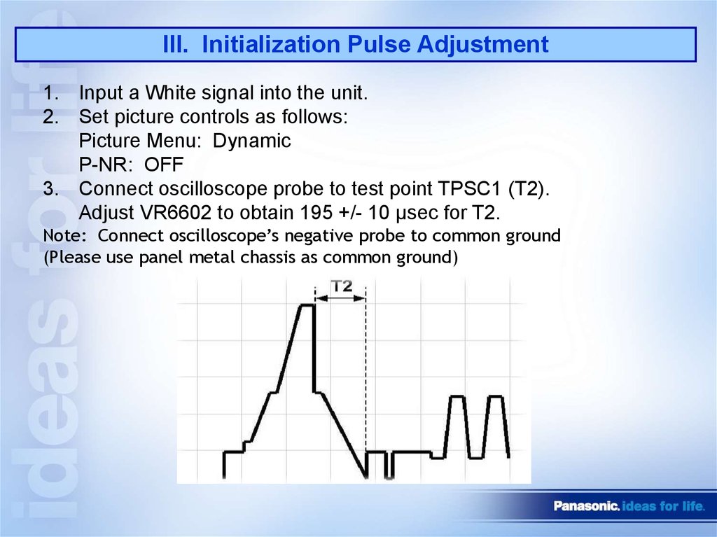
III. Initialization Pulse Adjustment1. Input a White signal into the unit.
2. Set picture controls as follows:
Picture Menu: Dynamic
P-NR: OFF
3. Connect oscilloscope probe to test point TPSC1 (T2).
Adjust VR6602 to obtain 195 +/- 10 µsec for T2.
Note: Connect oscilloscope’s negative probe to common ground
(Please use panel metal chassis as common ground)
7.
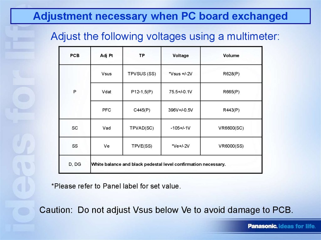
Adjustment necessary when PC board exchangedAdjust the following voltages using a multimeter:
PCB
Adj Pt
TP
Voltage
Volume
Vsus
TPVSUS (SS)
*Vsus +/-2V
R628(P)
Vdat
P12-1,5(P)
75.5+/-0.1V
R665(P)
PFC
C445(P)
396V+/-0.5V
R443(P)
SC
Vad
TPVAD(SC)
-105+/-1V
VR6600(SC)
SS
Ve
TPVE(SS)
*Ve+/-2V
VR6000(SS)
P
D, DG
White balance and black pedestal level confirmation necessary.
*Please refer to Panel label for set value.
Caution: Do not adjust Vsus below Ve to avoid damage to PCB.
8.
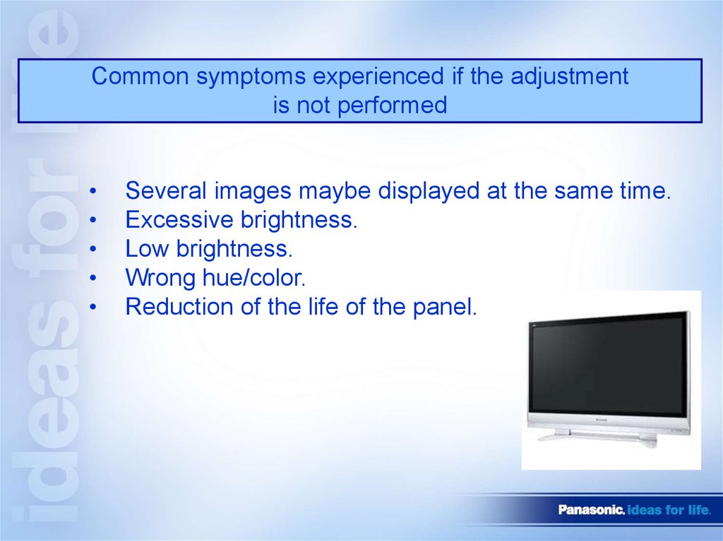
Common symptoms experienced if the adjustmentis not performed
Several images maybe displayed at the same time.
Excessive brightness.
Low brightness.
Wrong hue/color.
Reduction of the life of the panel.
9.
POWER SUPPLY10. Sequence of events when Plasma TV is plugged in
When a Plasma TV is plugged in, there are a few indications of normaloperation. Knowing these will help us understand what’s going on with
the unit when an abnormality occurs.
1. There is a click from relay RL402 and RL403 when they are
activated.
2. The LED in the optical jack (inside the DT board) turns ON for
approximately 4 seconds.
3. Immediately after, the relay click the Tuner LEDs turn ON for
approximately 20 seconds.
4. The LED in the optical jack turns ON again for approximately
1 second and both LEDs (tuner and optical jack) turn OFF.
5. Then another click is audible from relays RL402 & RL403,
indicating that they are no longer engaged. Note at this time, LEDs
(for Tuner & optical jack) are turned OFF.
11.
Standby Block (Part1)12.
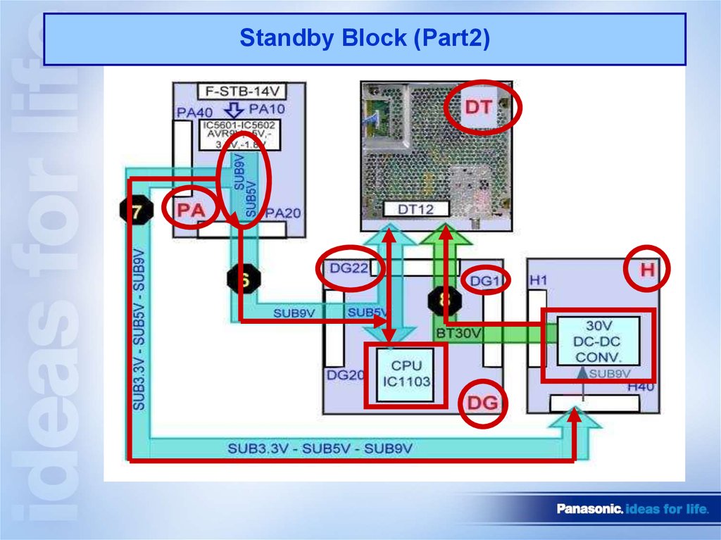
Standby Block (Part2)13.
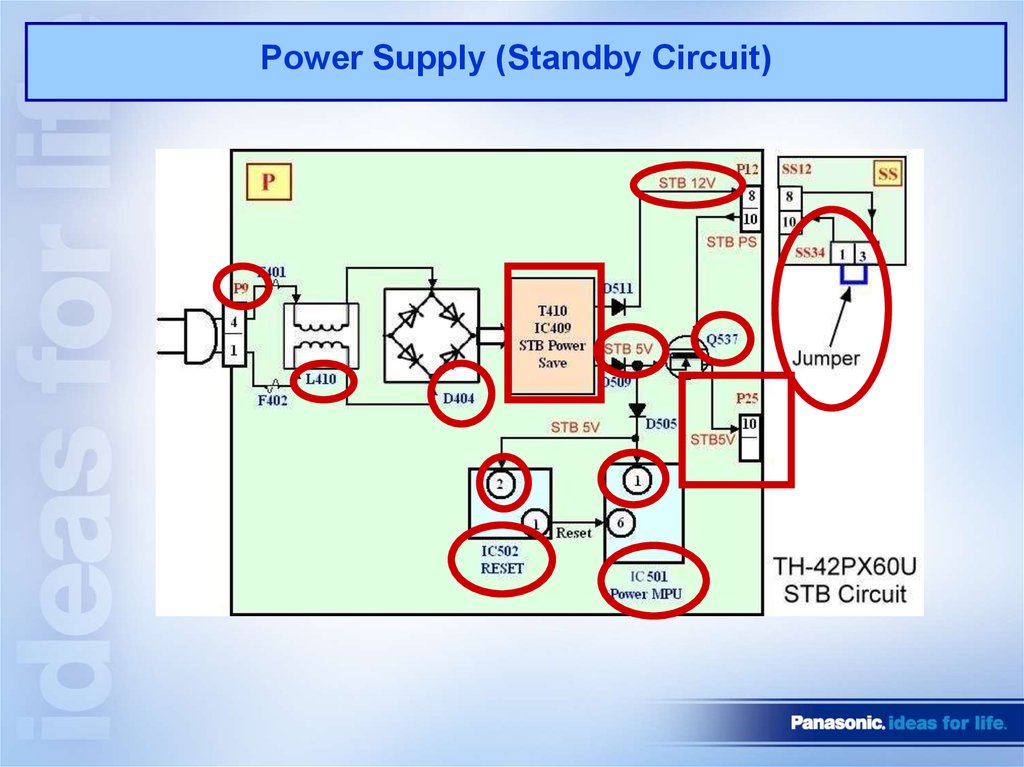
Power Supply (Standby Circuit)14.
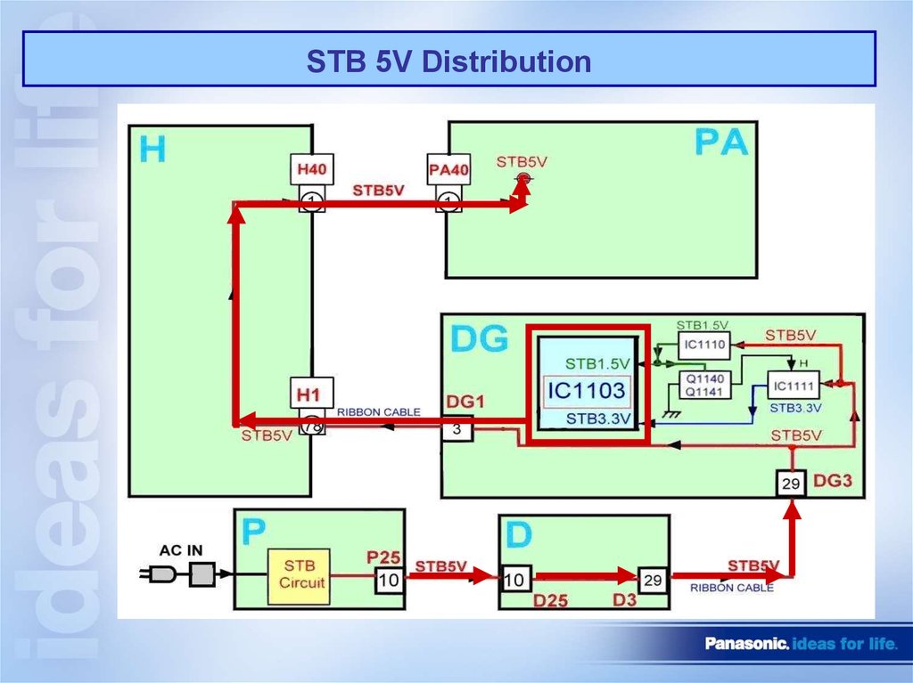
STB 5V Distribution15.
Power Supply (Standby Circuit)16.
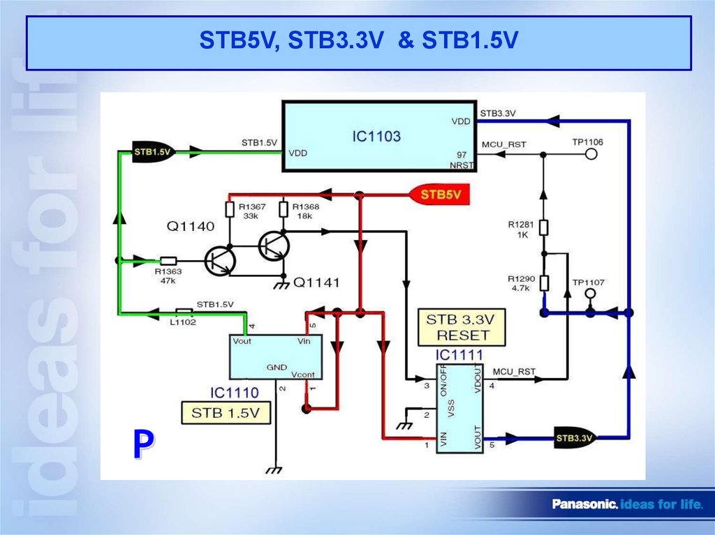
STB5V, STB3.3V & STB1.5VP
17.
F-STB-ON (Primary)P
18.
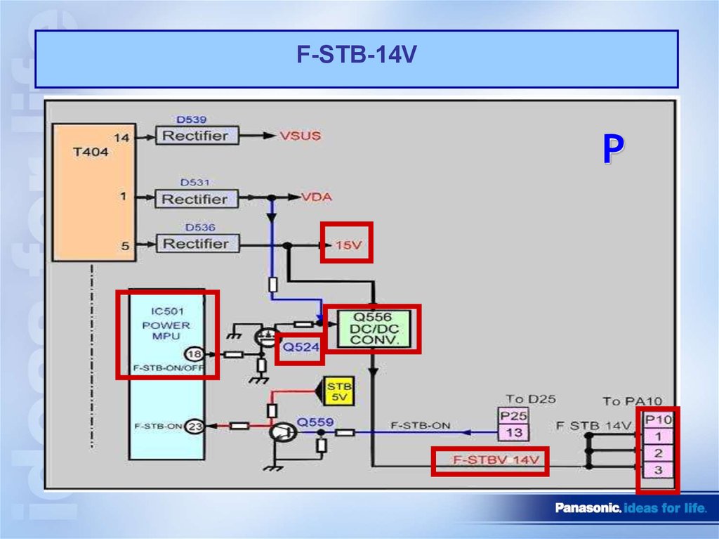
F-STB-14VP
19.
STB5V and TV-SUB-ON function on PA boardPA
20.
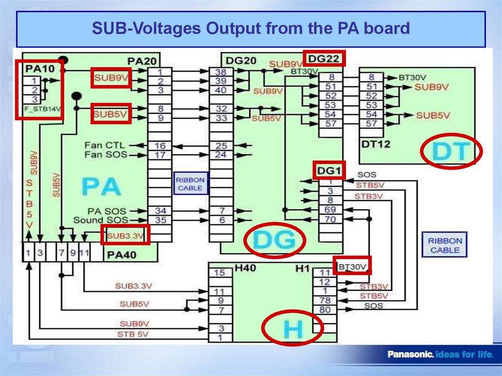
SUB-Voltages Output from the PA board21.
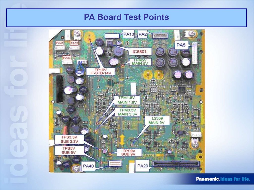
PA Board Test Points22.
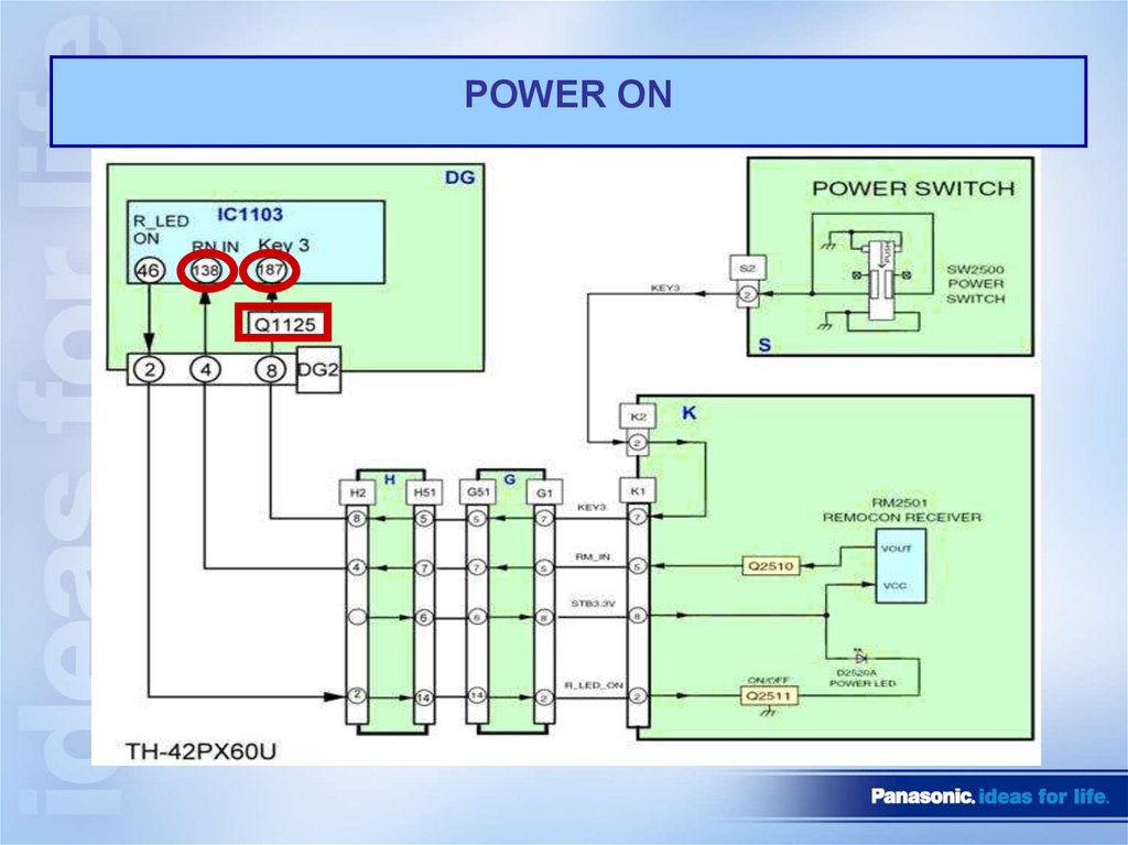
POWER ON23.
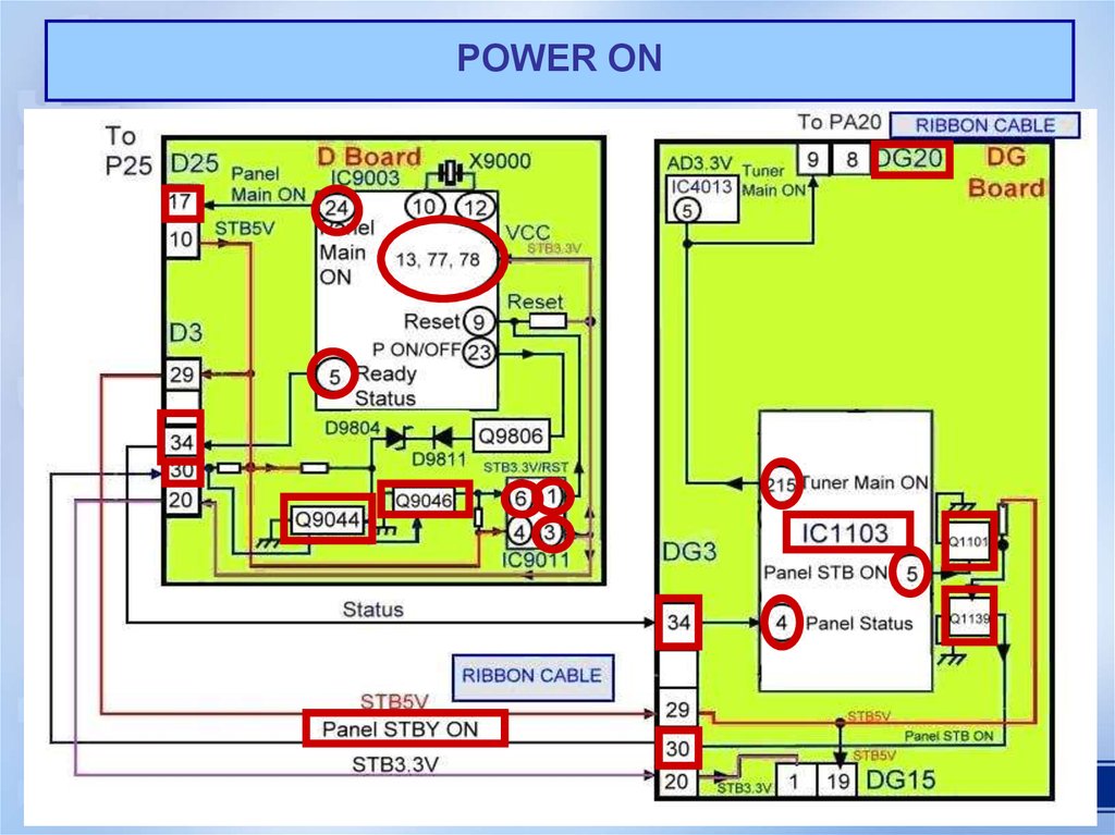
POWER ON24.
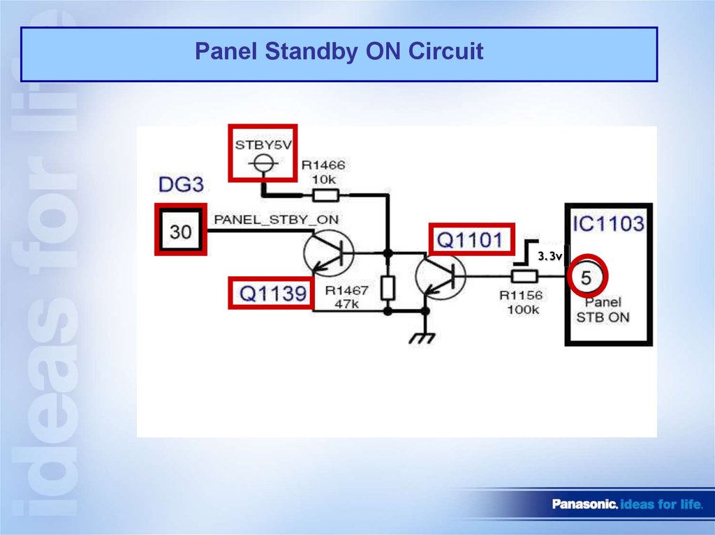
Panel Standby ON Circuit3.3v
25.
Power Supply Secondary Circuit26.
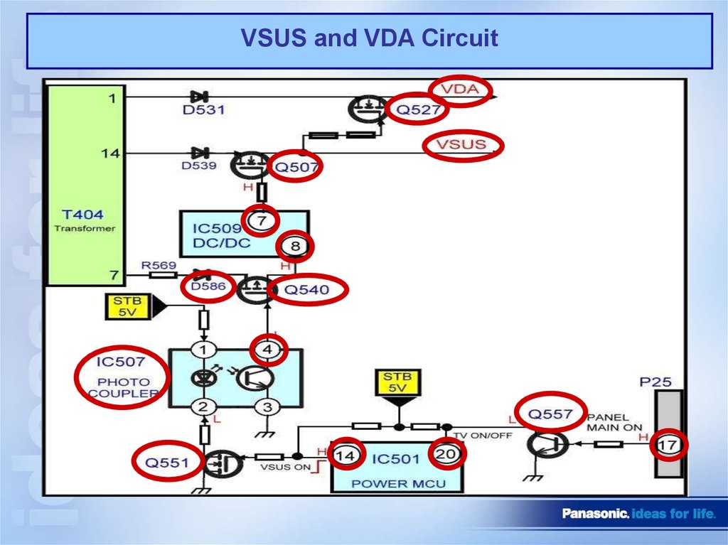
VSUS and VDA Circuit27.
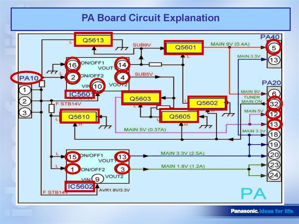
PA Board Circuit Explanation28.
Main voltages output from the PA Circuit29.
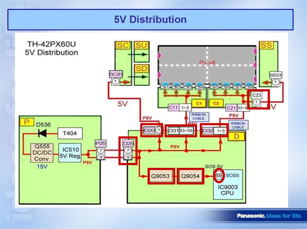
5V Distribution30.
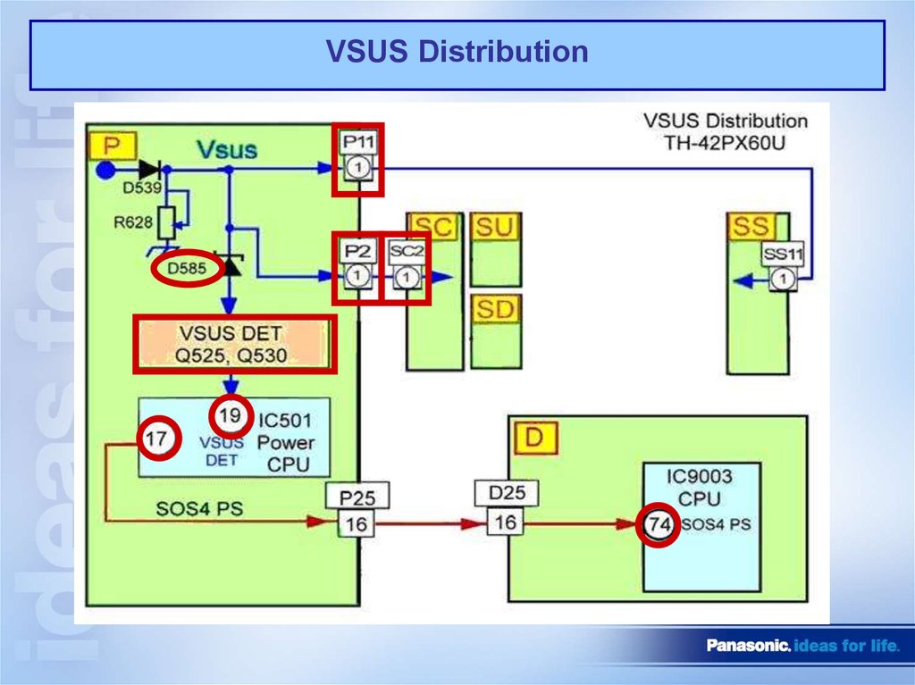
VSUS Distribution31.
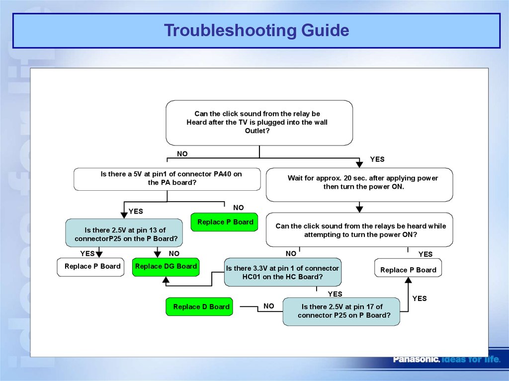
Troubleshooting GuideCan the click sound from the relay be
Heard after the TV is plugged into the wall
Outlet?
NO
YES
Is there a 5V at pin1 of connector PA40 on
the PA board?
Wait for approx. 20 sec. after applying power
then turn the power ON.
NO
YES
Replace P Board
Can the click sound from the relays be heard while
attempting to turn the power ON?
Is there 2.5V at pin 13 of
connectorP25 on the P Board?
YES
Replace P Board
NO
Replace DG Board
NO
YES
Is there 3.3V at pin 1 of connector
HC01 on the HC Board?
Replace P Board
YES
Replace D Board
NO
Is there 2.5V at pin 17 of
connector P25 on P Board?
YES
32.
Thank YouFor Completing Course Two
Course Three
Understanding How System
Shut Down Operates