
 Физика
Похожие презентации:


")


")
Mathematical Modeling of Energy Efficiency
1.
Mathematical Modeling of EnergyEfficiency
Lecture 1 – Introduction. Basic
notions. Graphs. Incidence
matrixes
Lecturer: Masheyeva R.U.
2.
Introduction. Basic notions. Graphs. Incidence matrixesFormalized topological methods for the analysis of
electrical circuits
These methods are based on the use of basic concepts of
topology and provide automatic generation of models of
electrical circuits.
The basis of electrical circuits are active two-terminal
networks, which have equivalent resistances and EMF, and
passive ones, which have only resistance, and the EMF is
zero.
Auto two-pole networks are sources of EMF and current,
batteries, generators, electric motors;
Passive two-pole networks are transformers, load
resistance lines;
Lecturer: Masheyeva R.U.
3.
Introduction. Basic notions. Graphs. Incidence matrixesThe connection point of two or more electrical circuits is
called a node or a node is the point of connection between two or
more branches.
Links between nodes are called branches.
A branch represents a single element such as a voltage
source or a resistor. In other words, a branch represents
any two-terminal element.
The branches form loops. A loop is any closed path in a circuit.
Lecturer: Masheyeva R.U.
4.
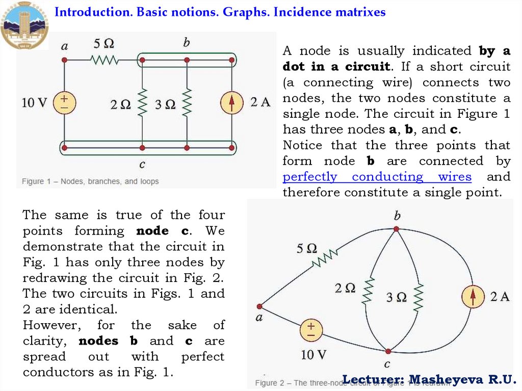
Introduction. Basic notions. Graphs. Incidence matrixesA node is usually indicated by a
dot in a circuit. If a short circuit
(a connecting wire) connects two
nodes, the two nodes constitute a
single node. The circuit in Figure 1
has three nodes a, b, and c.
Notice that the three points that
form node b are connected by
perfectly conducting wires and
therefore constitute a single point.
The same is true of the four
points forming node c. We
demonstrate that the circuit in
Fig. 1 has only three nodes by
redrawing the circuit in Fig. 2.
The two circuits in Figs. 1 and
2 are identical.
However, for the sake of
clarity, nodes b and c are
spread
out
with
perfect
conductors as in Fig. 1.
Lecturer: Masheyeva R.U.
5.
Introduction. Basic notions. Graphs. Incidence matrixesA loop is a closed path formed by starting at a node, passing
through a set of nodes, and returning to the starting node without
passing through any node more than once. A loop is said to be
independent if it contains at least one branch which is not a part of
any other independent loop. Independent loops or paths result in
independent sets of equations.
It is possible to form an independent set of loops where one of the
loops does not contain such a branch. In Fig. 2, abca with the 2Ω
resistor is independent. A second loop with the 3Ω resistor and the
current source is independent. The third loop could be the one with
the 2Ω resistor in parallel with the 3Ω resistor. This does form an
independent set of loops.
A network with b branches, n nodes, and I independent loops will
satisfy the fundamental theorem of network topology
b= I+n-1
Lecturer: Masheyeva R.U.
6.
Introduction. Basic notions. Graphs. Incidence matrixesThe method of connecting branches and nodes of an electrical circuit, that
is, a structural diagram of a circuit, is presented in the form of a directed
graph (Граф), the tops of which correspond to the nodes of the circuit, and
the edges correspond to its branches.
Sources of EMF, current, resistance do not show in this graphs but only
take into account the nodes and their circuits.
For each branch, its orientation (positive direction) is set, in accordance
with which the positive directions of the current and voltage of the branch
are taken. We will take the direction of the current in the branch to the
node as a positive direction. For loop currents, we take the clockwise
direction as positive. Under these conditions, any electrical circuit can be
represented in the form of a graph and P matrix, connections that uniquely
reflects the structural diagram of the graph.
Lecturer: Masheyeva R.U.
7.
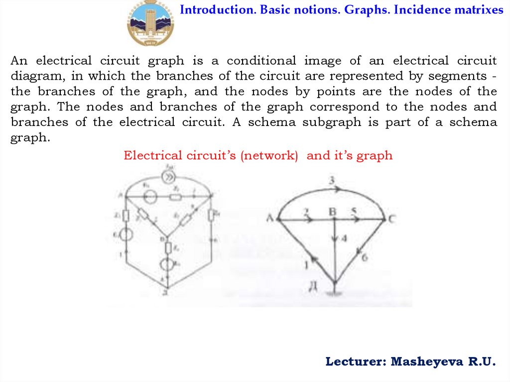
Introduction. Basic notions. Graphs. Incidence matrixesAn electrical circuit graph is a conditional image of an electrical circuit
diagram, in which the branches of the circuit are represented by segments the branches of the graph, and the nodes by points are the nodes of the
graph. The nodes and branches of the graph correspond to the nodes and
branches of the electrical circuit. A schema subgraph is part of a schema
graph.
Electrical circuit’s (network) and it’s graph
Lecturer: Masheyeva R.U.
8.
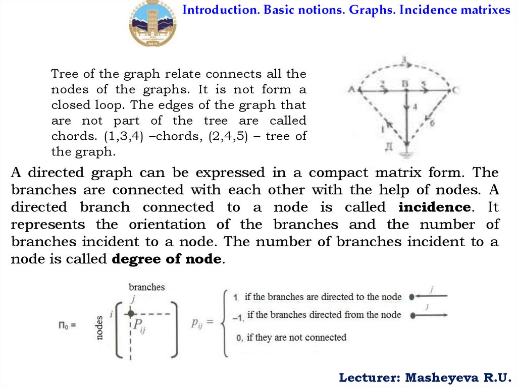
Introduction. Basic notions. Graphs. Incidence matrixesTree of the graph relate connects all the
nodes of the graphs. It is not form a
closed loop. The edges of the graph that
are not part of the tree are called
chords. (1,3,4) –chords, (2,4,5) – tree of
the graph.
A directed graph can be expressed in a compact matrix form. The
branches are connected with each other with the help of nodes. A
directed branch connected to a node is called incidence. It
represents the orientation of the branches and the number of
branches incident to a node. The number of branches incident to a
node is called degree of node.
Lecturer: Masheyeva R.U.
9.
Introduction. Basic notions. Graphs. Incidence matrixesOrder of incidence matrix: If there are 'n’ nodes and 'b’ branches in a
network graph, then incidence matrix have 'n’ rows and 'b’ columns. So
order of the incidence matrix in nxb.
Reduced incidence matrix (A): When any one row is completely
deleted from the matrix then this is called reduced incidence
matrix. The order of this matrix is (n-1)xb. This reduction results from
mathematical manipulation.
Lecturer: Masheyeva R.U.
10.
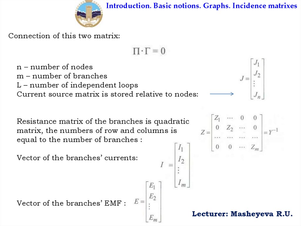
Introduction. Basic notions. Graphs. Incidence matrixesConnection of this two matrix:
n – number of nodes
m – number of branches
L – number of independent loops
Current source matrix is stored relative to nodes:
Resistance matrix of the branches is quadratic
matrix, the numbers of row and columns is
equal to the number of branches :
Vector of the branches’ currents:
Vector of the branches’ EMF :
Lecturer: Masheyeva R.U.