


 Электроника
Похожие презентации:

 & Compressor Dehydrator")


Training course
1.
TRAINING COURSETRANSMITTER GROUP (TXG)
Primary Surveillance Radar
ATM
Nº doc.: 0066605020000MA04
Edición: A Revisión: 1
Fecha: 09/03/2020
2.
Warning of ConfidentialityThe data and information, in its totality or partial expression, contained in this document are property of
Indra Sistemas, S.A. This data and information cannot be disclosed totally or partially to third parties.
The copy, reproduction, public communication, dissemination, total or partial distribution, modification or
assignment will require the prior written authorization of Indra Sistemas, S.A. Its content cannot be used
for different purposes to those for which it is provided, its use being limited to the execution of the
Program it is supplied for.
0066605020000MA04 _A1
09/03/2020
2 de 46
3.
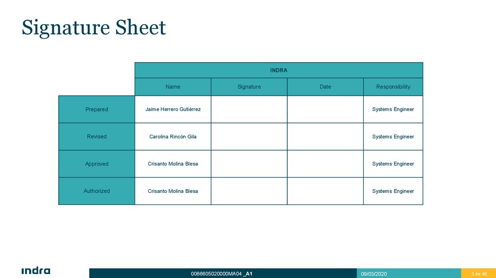
Signature SheetINDRA
Name
Signature
Date
Responsibility
Prepared
Jaime Herrero Gutiérrez
Systems Engineer
Revised
Carolina Rincón Gila
Systems Engineer
Approved
Crisanto Molina Blesa
Systems Engineer
Authorized
Crisanto Molina Blesa
Systems Engineer
0066605020000MA04 _A1
09/03/2020
3 de 463
4.
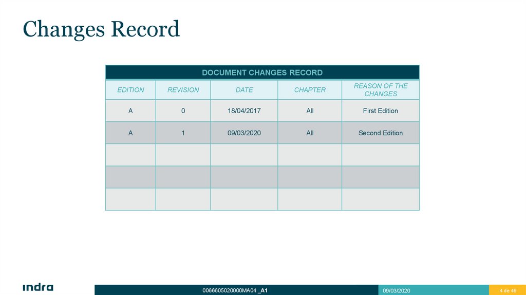
Changes RecordDOCUMENT CHANGES RECORD
EDITION
REVISION
DATE
CHAPTER
REASON OF THE
CHANGES
A
0
18/04/2017
All
First Edition
A
1
09/03/2020
All
Second Edition
0066605020000MA04 _A1
09/03/2020
4 de 464
5.
AcronymsAC
Alternate Current
BITE
Built-in test Equipment
BPS
Bulk Power Supply
CMS
Control and Monitor System
CPC
Central Processor Computer
dB
Decibel
dBC
Decibel (relative to carrier)
dBM
Decibel (relative to miliwatt)
DC
Direct Current
EPG
Exciter and Processor Group
GRPG
Generator, Receiver and Processor Group
Kw
Kilowatt
LRU
Line Replaceable Unit
MVPS
Multivoltage Power Supply
mW
milliWatt
0066605020000MA04 _A1
09/03/2020
5 de 46
6.
AcronymsMWG
Microwave Group
NM (nmi)
Nautical Miles
PA
Power Amplifier
PRPA
Previous Power Amplifier
PSR
Primary Surveillance Radar
RF
Radiofrequency
SLG
Local Control System
TXCU
Transmission Control Unit
TXG
Transmitter Group
TXGU
Transmission Generation Unit
VSWR
Video Standing Wave Ratio
w
WATT
3PST
Three Pole Single Throw
0066605020000MA04 _A1
09/03/2020
6 de 46
7.
IndexIndex
Introduction
1
Functional Description
2
Signal Path
Amplification Chain
Fail Soft Operation
LRU List and Interfaces
LRU List
Power Distribution
Interfaces
3
8.
IndexIndex
Subgroup Physical Description
General Diagram
General Description
Transmitter Control Unit (TXCU)
Preamplifier Panels (PRPA)
Power Amplifiers (PA)
Splitter/Combiner Assembly
Blower Assembly
Power Supply
Auxiliary Elements
4
9.
Introduction1
10.
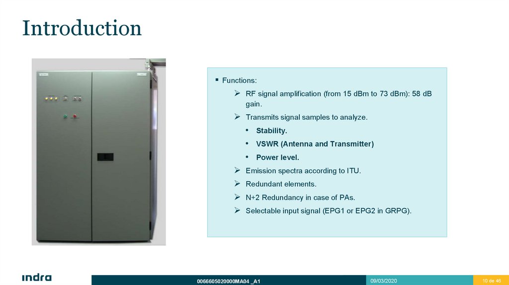
IntroductionFunctions:
RF signal amplification (from 15 dBm to 73 dBm): 58 dB
gain.
Transmits signal samples to analyze.
• Stability.
• VSWR (Antenna and Transmitter)
• Power level.
Emission spectra according to ITU.
Redundant elements.
N+2 Redundancy in case of PAs.
Selectable input signal (EPG1 or EPG2 in GRPG).
0066605020000MA04 _A1
09/03/2020
10 de 46
11.
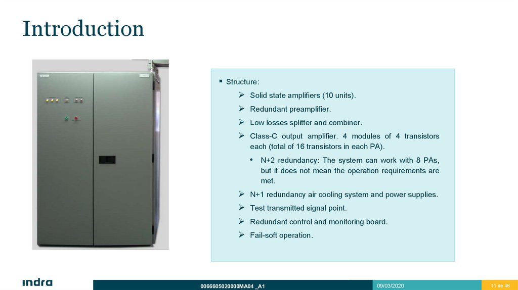
IntroductionStructure:
Solid state amplifiers (10 units).
Redundant preamplifier.
Low losses splitter and combiner.
Class-C output amplifier. 4 modules of 4 transistors
each (total of 16 transistors in each PA).
• N+2 redundancy: The system can work with 8 PAs,
but it does not mean the operation requirements are
met.
N+1 redundancy air cooling system and power supplies.
Test transmitted signal point.
Redundant control and monitoring board.
Fail-soft operation.
0066605020000MA04 _A1
09/03/2020
11 de 46
12.
IntroductionFront view.
TWO DOORS
CIRCUIT BREAKERS
CONTROL & MONITOR
BOARDS
10 RF AMPLIFIER
PANELS
(FAIL-SOFT)
REDUNDANT PREAMPLIFIERS
TX SIGNAL
SAMPLE
CONNECTOR
REDUNDANT MULTI VOLTAGE POWER
SUPPLIES
0066605020000MA04 _A1
REDUNDANT
BLOWERS
REDUNDANT BULK
POWER SUPPLIES
09/03/2020
12 de 46
13.
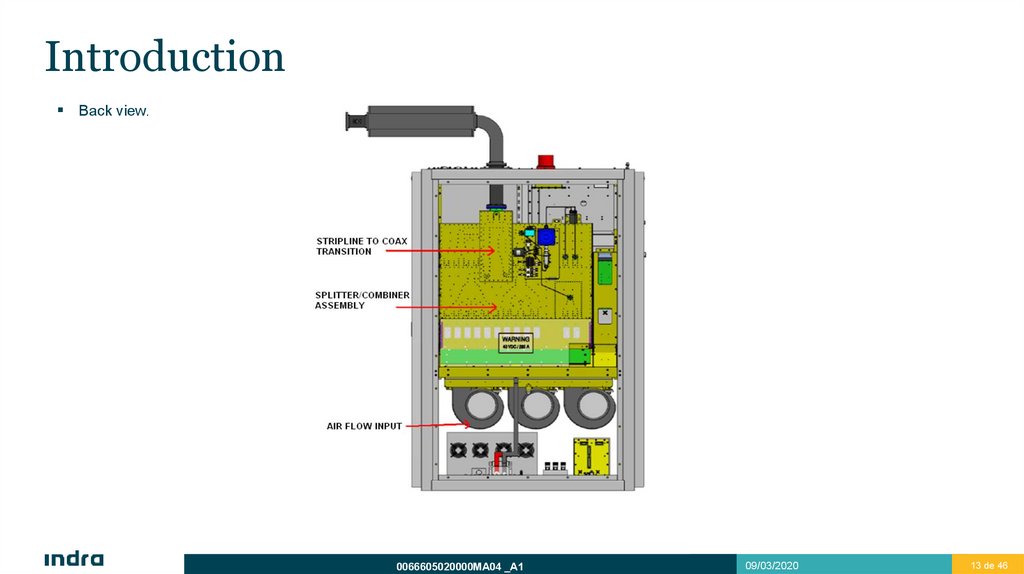
IntroductionBack view.
0066605020000MA04 _A1
09/03/2020
13 de 46
14.
IntroductionFailure LEDs on the door:
Power input: Ф1, Ф2, Ф3. Three phases, yellow colour.
Soft Failure: Unit Failure. Orange colour.
Hard Failure: Interlock or Blower fault. Red colour.
Lamp Test: Green button.
Inhibit transmission manually: Red button.
0066605020000MA04 _A1
09/03/2020
14 de 46
15.
Functional DescriptionSignal Path
Amplification Chain
Soft Failure Operation
2
16.
Signal Path1.
RF input signal selection: TXGU 1 or TXGU 2
output.
2.
Signal division in two equal parts to PRPAs.
3.
Amplification in both PRPAs.
4.
Active PRPA selection. The signal from standby PRPA is sent to a RF short-circuit.
5.
Division of active PRPA signal into 10 equal
parts to PAs.
6.
Amplification in all PAs.
7.
Addition of the 10 PAs output signals.
8.
Signal output from TXG to harmonic filter and
antenna.
0066605020000MA04 _A1
09/03/2020
16 de 46
17.
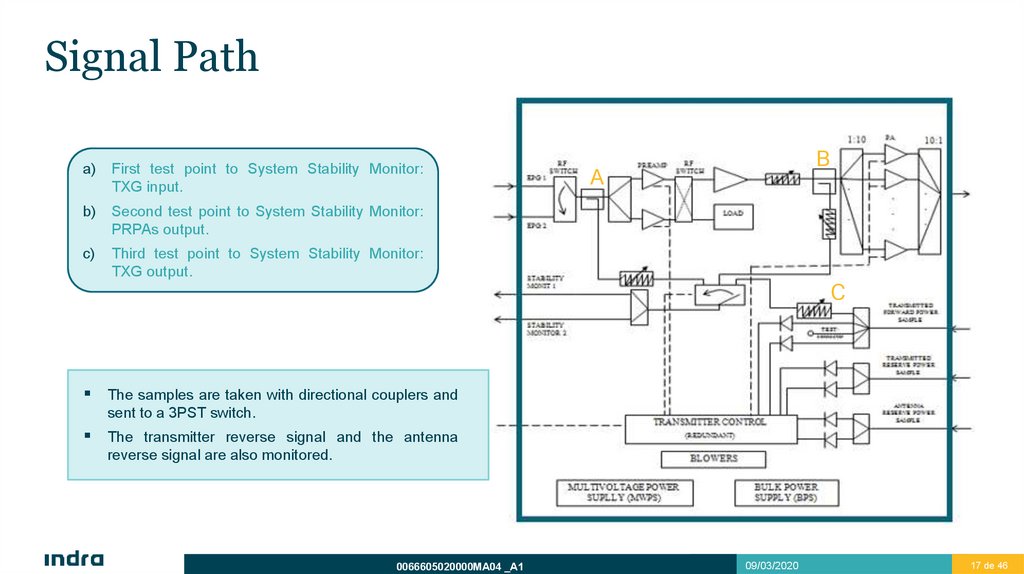
Signal Patha)
First test point to System Stability Monitor:
TXG input.
b)
Second test point to System Stability Monitor:
PRPAs output.
c)
Third test point to System Stability Monitor:
TXG output.
B
A
C
The samples are taken with directional couplers and
sent to a 3PST switch.
The transmitter reverse signal and the antenna
reverse signal are also monitored.
0066605020000MA04 _A1
09/03/2020
17 de 46
18.
Signal Path0066605020000MA04 _A1
09/03/2020
18 de 46
19.
Amplification ChainDual Redundant Pre-Amplifiers.
Hot Pluggable and Removable.
Automatic Switching in case of failure
10 Power Amplifiers.
Hot Pluggable and Removable (switching
off power supply from CMS).
Total of 16 Transistors in each PA.
Soft Failure until 20% transistors had failed.
Peak Power 22 kW.
0066605020000MA04 _A1
09/03/2020
19 de 46
20.
Fail-Soft OperationSeveral transistors of the transmitter can fail without degrading radar performance significantly.
The system is able to operate in soft failure mode until 32 out of 160 transistors are broken.
0066605020000MA04 _A1
09/03/2020
20 de 46
21.
Fail-Soft OperationThis power reduction carries on a coverage reduction until 60 NM as minimum.
0066605020000MA04 _A1
09/03/2020
21 de 46
22.
LRU List andInterfaces
LRU List
Power Distribution
Interfaces
3
23.
LRU ListTransmitter Control Unit, TXCU (2).
Power Amplifier, PA (10).
Power Preamplifier, PRPA (2).
Multivoltage Power Supply, MVPS (2).
Bulk Power Supply, BPS (4).
Blowers (3).
0066605020000MA04 _A1
09/03/2020
23 de 46
24.
Power Distribution0066605020000MA04 _A1
09/03/2020
24 de 46
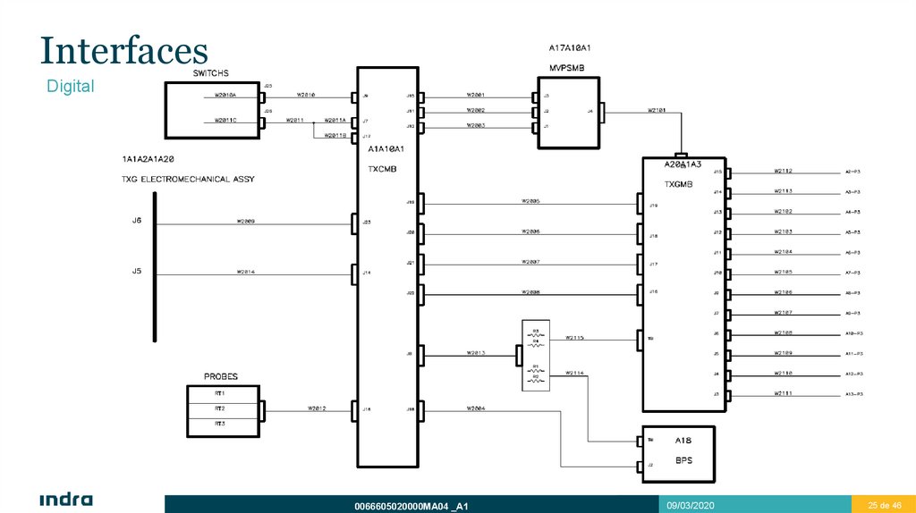
25.
InterfacesDigital
0066605020000MA04 _A1
09/03/2020
25 de 46
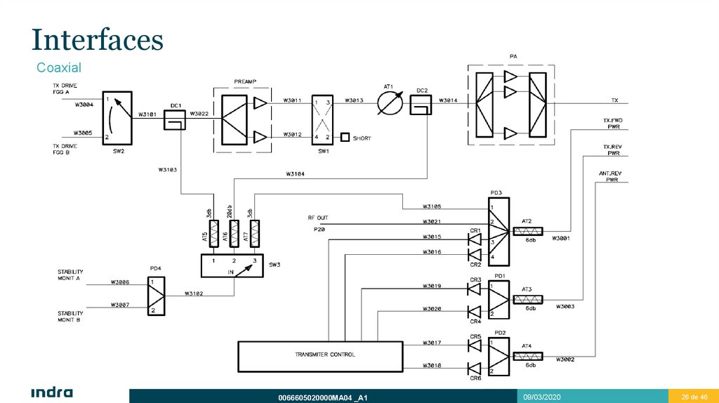
26.
InterfacesCoaxial
0066605020000MA04 _A1
09/03/2020
26 de 46
27.
Subgroup PhysicalDescription
General Diagram
General Description
Transmitter Control Unit (TXCU)
Preamplifier Panels (PRPA)
Power Amplifiers (PA)
Splitter/Combiner Assembly
Blower Assembly
Power Supply
Auxiliary Elements
4
28.
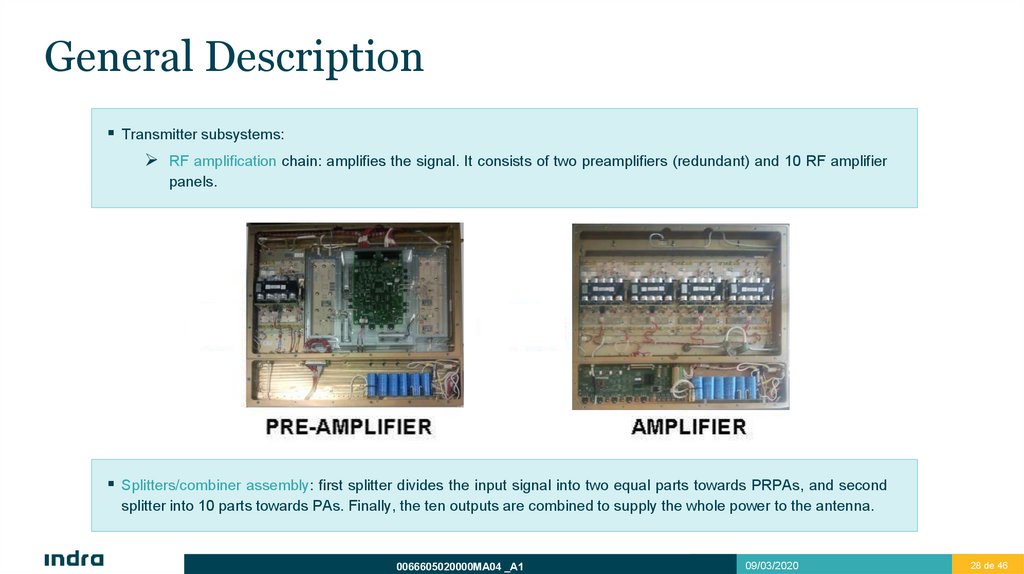
General DescriptionTransmitter subsystems:
RF amplification chain: amplifies the signal. It consists of two preamplifiers (redundant) and 10 RF amplifier
panels.
Splitters/combiner assembly: first splitter divides the input signal into two equal parts towards PRPAs, and second
splitter into 10 parts towards PAs. Finally, the ten outputs are combined to supply the whole power to the antenna.
0066605020000MA04 _A1
09/03/2020
28 de 46
29.
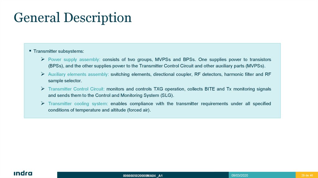
General DescriptionTransmitter subsystems:
Power supply assembly: consists of two groups, MVPSs and BPSs. One supplies power to transistors
(BPSs), and the other supplies power to the Transmitter Control Circuit and other auxiliary parts (MVPSs).
Auxiliary elements assembly: switching elements, directional coupler, RF detectors, harmonic filter and RF
sample selector.
Transmitter Control Circuit: monitors and controls TXG operation, collects BITE and Tx monitoring signals
and sends them to the Control and Monitoring System (SLG).
Transmitter cooling system: enables compliance with the transmitter requirements under all specified
conditions of temperature and altitude (forced air).
0066605020000MA04 _A1
09/03/2020
29 de 46
30.
Transmitter Control Unit (TXCU)Redundant Unit. Automatic
switching if failure. It can be
switched manually from
CMS.
Monitors and controls the
transmitter operation.
0066605020000MA04 _A1
09/03/2020
30 de 46
31.
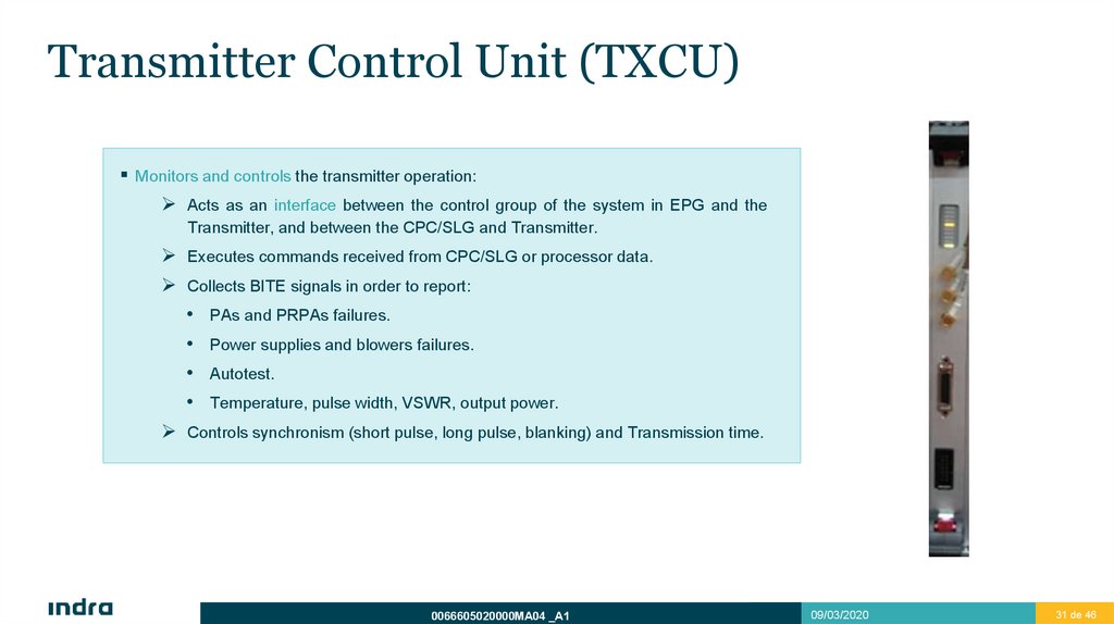
Transmitter Control Unit (TXCU)Monitors and controls the transmitter operation:
Acts as an interface between the control group of the system in EPG and the
Transmitter, and between the CPC/SLG and Transmitter.
Executes commands received from CPC/SLG or processor data.
Collects BITE signals in order to report:
PAs and PRPAs failures.
Power supplies and blowers failures.
Autotest.
Temperature, pulse width, VSWR, output power.
Controls synchronism (short pulse, long pulse, blanking) and Transmission time.
0066605020000MA04 _A1
09/03/2020
31 de 46
32.
Transmitter Control Unit (TXCU)Monitors and controls the transmitter operation:
If a critical failure occurs, TXCU detects and reports it, then activates an interlock if
required (inhibits transmission):
• Antenna safety switch.
• Deactivation of radiation from the transmitter front panel.
• Two out of three blowers failure.
• Over-voltage in 40V power supplies, or two out of four power supplies failures.
• Less than 8 PAs operating correctly.
• Communication Ethernet with the data processor failure.
• Operative preamplifier and transfer switch position do not match up.
• System clock failure.
Select RF signal generation from EPG 1 or EPG 2.
Select the active preamplifier.
0066605020000MA04 _A1
09/03/2020
32 de 46
33.
Transmitter Control Unit (TXCU)0066605020000MA04 _A1
09/03/2020
33 de 46
34.
Preamplifier Panels (PRPA)Redundant element. Automatic switching in case of failure. Manually switching is also allowed.
First element in RF transmitter chain. Amplifies the signal from the TXGU output into the appropriate level to excite
the next amplification stage.
Controls that the amplified signal does not exceed pulse-width restrictions or duty cycle. In addition, it avoids these
failures to propagate and damage subsequent devices.
0066605020000MA04 _A1
09/03/2020
34 de 46
35.
Preamplifier Panels (PRPA)Amplification stages: consists of insulators to ensure stability and facilitate adjustment.
Low-level amplifier chain: the input signal will be about 12 dBm and it shall be amplified to 36 dBm (4 W)
required at the amplifier module input, carried on in two stages.
Amplifier module: transmitter basic amplification unit, made up of 3 cascaded amplification stages.
Provides a minimum output signal of 57.7 dBm (600 w) (PRPA Output).
Control board and regulators:
Control and BITE: enable/disable PRPA, synchronization, duty cycle and pulse width protection,
enable/disable regulator loads and BITE reporting to TXCU.
Regulators: adjust amplifier supply, control gain and output power.
0066605020000MA04 _A1
09/03/2020
35 de 46
36.
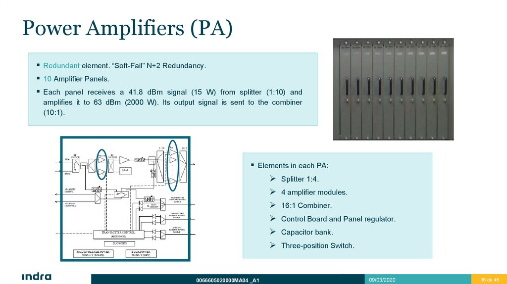
Power Amplifiers (PA)Redundant element. “Soft-Fail” N+2 Redundancy.
10 Amplifier Panels.
Each panel receives a 41.8 dBm signal (15 W) from splitter (1:10) and
amplifies it to 63 dBm (2000 W). Its output signal is sent to the combiner
(10:1).
Elements in each PA:
Splitter 1:4.
0066605020000MA04 _A1
4 amplifier modules.
16:1 Combiner.
Control Board and Panel regulator.
Capacitor bank.
Three-position Switch.
09/03/2020
36 de 46
37.
Power Amplifiers (PA)Splitter 1:4: Divides signal to distribute it into four amplifier modules.
Amplifier modules: same as PRPA’s.
Combiner 16:1: adds the outputs of the 16 Transistors (4 each PAM).
Control Board and Panel Regulator: performs the following functions:
Communication with TXCU: receives control orders and sends BITE reports.
Controls the PIN diodes for shaping the transmitted pulses.
Receives BITE from the modules.
Regulates 40 V power into 36 V and supplies modules.
0066605020000MA04 _A1
09/03/2020
37 de 46
38.
Power Amplifiers (PA)Capacitor Bank:
5 parallel capacitors operate as voltage supply filter. Acts as energy store in order to allow fast loading of Capacitors Bank
incorporated in each RF amplifier modules. Capacitor Bank is made of 6 capacitors in parallel, which are loaded with the
voltage of direct current Bus from the power supplies, being a filter for this voltage. This capacitor bank is a power storage
to get the capacitor bank of each PA loaded between transmissions.
Three-Position Switch:
Prevents against stored energy in the capacitors bank. Allows extraction or insertion of the PA in the transmitter (“hotrepair”) without high transient.
0066605020000MA04 _A1
09/03/2020
38 de 46
39.
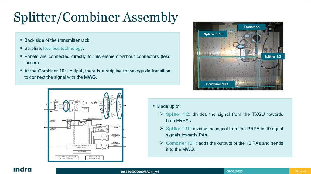
Splitter/Combiner AssemblyTransition
Splitter 1:10
Back side of the transmitter rack.
Stripline, low loss technology.
Panels are connected directly to this element without connectors (less
Splitter 1:2
losses).
At the Combiner 10:1 output, there is a stripline to waveguide transition
to connect the signal with the MWG.
Combiner 10:1
Made up of:
Splitter 1:2: divides the signal from the TXGU towards
both PRPAs.
Splitter 1:10: divides the signal from the PRPA in 10 equal
signals towards PAs.
Combiner 10:1: adds the outputs of the 10 PAs and sends
it to the MWG.
0066605020000MA04 _A1
09/03/2020
39 de 46
40.
Blowers AssemblyRedundant Unit. N+1 redundancy, it can operate with 2 out of 3 blowers.
The TXG cooling operates using forced air.
The air flow is distributed from the bottom of PRPAs and PAs, passing through the four air inlet channels of each one, cooling the
RF amplifier modules heat sinks.
If a 1 out of 3 blowers failure is detected, an alarm is reported, but the TXG continues operation without any interruption.
If a failure in 2 out of 3 blowers is detected, an inhibiting transmission interlock will be enabled.
Air input and output are performed through EMI and dust filters.
0066605020000MA04 _A1
09/03/2020
40 de 46
41.
Power SupplyRedundant units. N+1 redundancy.
Two groups: MVPS y BPS.
MVPS: Multi Voltage Power Supplies.
Supplies +5V, +15V, -15V, -50V to PAs and PRPAs.
N+1 Redundancy On-Line Repair Capacity.
AC OK, DC OK LEDs; PWR ON/OFF and ENABLE ON/OFF
MVPS
BPS
switches.
BPS: Bulk Power Supplies.
Supplies +40 V to PAs and PRPAs.
N+1 Redundancy On-Line Repair Capacity.
AC OK, DC Output OK Indicators; ON/OFF switch.
Overheating, over-current and over-voltage protection.
0066605020000MA04 _A1
09/03/2020
41 de 46
42.
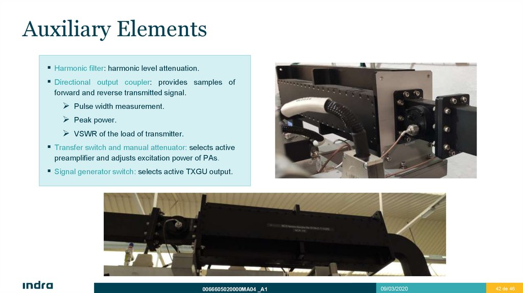
Auxiliary ElementsHarmonic filter: harmonic level attenuation.
Directional output coupler: provides samples of
forward and reverse transmitted signal.
Pulse width measurement.
Peak power.
VSWR of the load of transmitter.
Transfer switch and manual attenuator: selects active
preamplifier and adjusts excitation power of PAs.
Signal generator switch: selects active TXGU output.
0066605020000MA04 _A1
09/03/2020
42 de 46
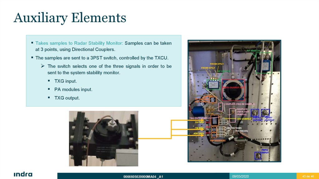
43.
Auxiliary ElementsTakes samples to Radar Stability Monitor: Samples can be taken
at 3 points, using Directional Couplers.
The samples are sent to a 3PST switch, controlled by the TXCU.
The switch selects one of the three signals in order to be
sent to the system stability monitor.
TXG input.
PA modules input.
TXG output.
0066605020000MA04 _A1
09/03/2020
43 de 46