
 Программное обеспечение
Похожие презентации:


")


MSE block library for Simulink
1. MSE block library for Simulink
Library – a function description language for an engineer• Minimum set of elementary operations for composing
control functions
• Integration with the data preparation system
• Automatic data scaling in operations
• Automatic data conversion into binary form and vice
versa
• Advanced diagnostics of data using accuracy
• Automatic generation of efficient code
2.
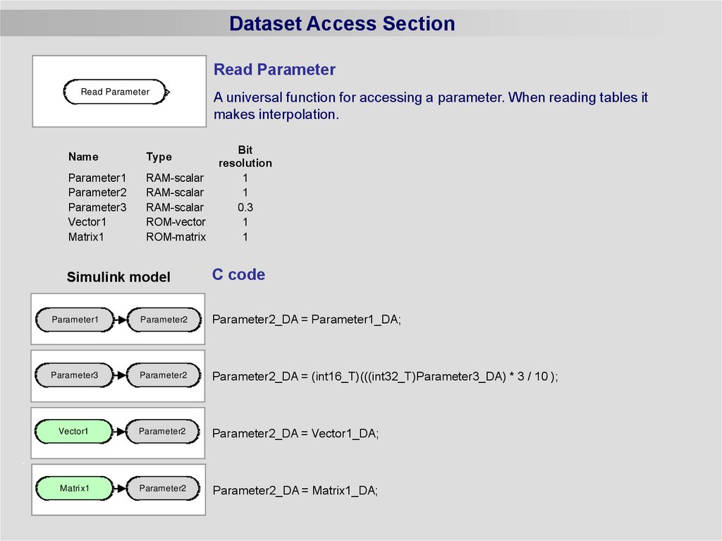
Dataset Access SectionRead Parameter
Read Parameter
Name
Type
Parameter1
Parameter2
Parameter3
Vector1
Matrix1
RAM-scalar
RAM-scalar
RAM-scalar
ROM-vector
ROM-matrix
Simulink model
A universal function for accessing a parameter. When reading tables it
makes interpolation.
Bit
resolution
1
1
0.3
1
1
C code
Parameter2_DA = Parameter1_DA;
Parameter1
Parameter1
Parameter2
Parameter2
Parameter1
Parameter2
Parameter3
Parameter3
Parameter2
Parameter2
Parameter3
Parameter2
Vector1
Parameter2
Parameter2_DA = Vector1_DA;
Matrix1
Parameter2
Parameter2_DA = Matrix1_DA;
Parameter2_DA = (int16_T)(((int32_T)Parameter3_DA) * 3 / 10 );
3.
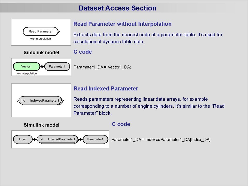
Dataset Access SectionRead Parameter without Interpolation
Read Parameter
w/o interpolation
Simulink model
Vector1
Parameter1
Extracts data from the nearest node of a parameter-table. It’s used for
calculation of dynamic table data.
C code
Parameter1_DA = Vector1_DA;
w/o interpolation
Read Indexed Parameter
Ind
IndexedParameter1
Reads parameters representing linear data arrays, for example
corresponding to a number of engine cylinders. It’s similar to the “Read
Parameter” block.
C code
Simulink model
Index
Ind
IndexedParameter1
Parameter1
Parameter1_DA = IndexedParameter1_DA[Index_DA];
4.
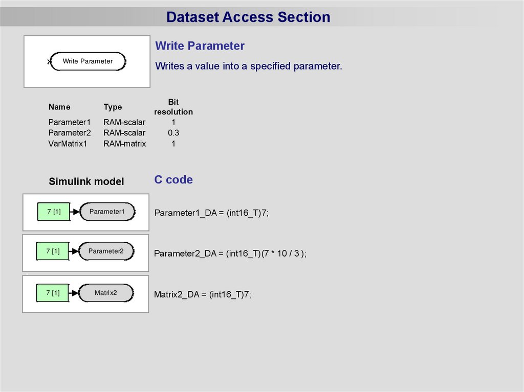
Dataset Access SectionWrite Parameter
Write Parameter
Name
Writes a value into a specified parameter.
Bit
resolution
RAM-scalar
1
RAM-scalar
0.3
RAM-matrix
1
Type
Parameter1
Parameter2
VarMatrix1
Simulink model
7 [1]
7 [1]
Parameter1
Parameter1
7 [1]
7 [1]
Parameter2
Parameter2
7 [1]
Matrix2
C code
Parameter1_DA = (int16_T)7;
Parameter2_DA = (int16_T)(7 * 10 / 3 );
Matrix2_DA = (int16_T)7;
5.
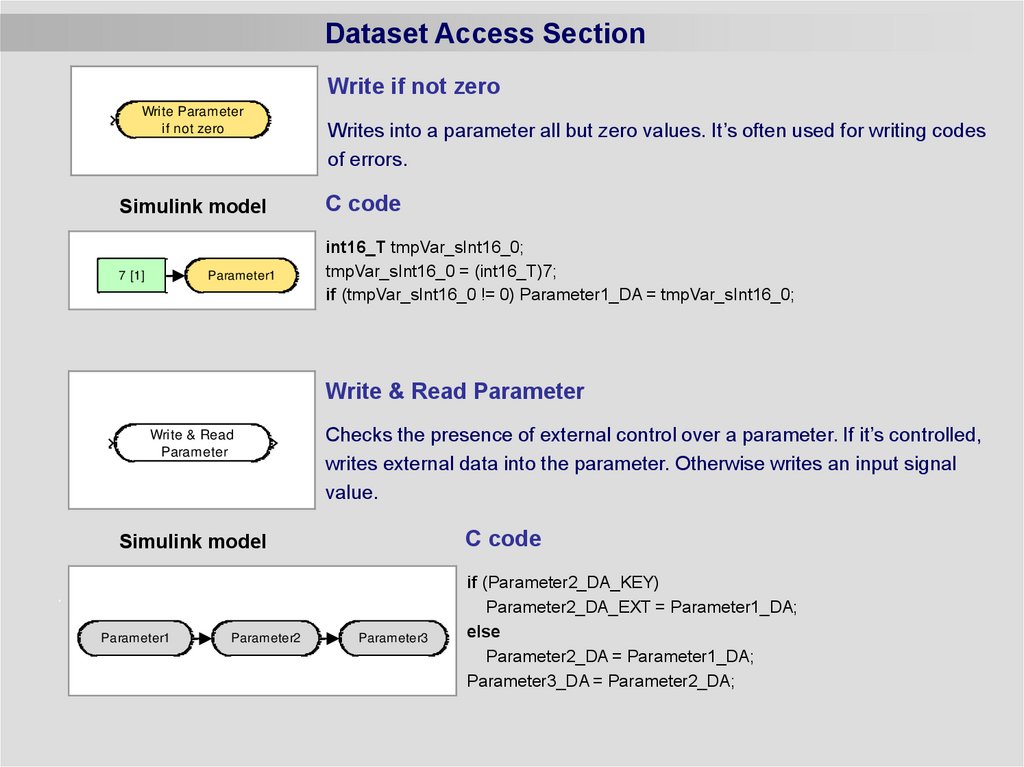
Dataset Access SectionWrite if not zero
Write Parameter
if not zero
Writes into a parameter all but zero values. It’s often used for writing codes
of errors.
Simulink model
C code
7 [1]
int16_T tmpVar_sInt16_0;
tmpVar_sInt16_0 = (int16_T)7;
if (tmpVar_sInt16_0 != 0) Parameter1_DA = tmpVar_sInt16_0;
Parameter1
Write & Read Parameter
Write & Read
Parameter
Checks the presence of external control over a parameter. If it’s controlled,
writes external data into the parameter. Otherwise writes an input signal
value.
C code
Simulink model
Parameter1
Parameter2
Parameter3
if (Parameter2_DA_KEY)
Parameter2_DA_EXT = Parameter1_DA;
else
Parameter2_DA = Parameter1_DA;
Parameter3_DA = Parameter2_DA;
6.
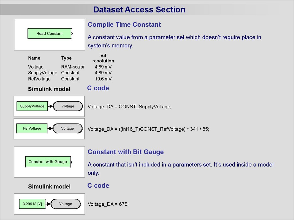
Dataset Access SectionCompile Time Constant
Read Constant
Name
Type
Voltage
RAM-scalar
SupplyVoltage Constant
RefVoltage
Constant
Simulink model
SupplyVoltage
SupplyVoltage
Voltage
Voltage
RefVoltage
RefVoltage
Voltage
Voltage
A constant value from a parameter set which doesn’t require place in
system’s memory.
Bit
resolution
4.89 mV
4.89 mV
19.6 mV
C code
Voltage_DA = CONST_SupplyVoltage;
Voltage_DA = ((int16_T)CONST_RefVoltage) * 341 / 85;
Constant with Bit Gauge
Constant with Gauge
A constant that isn’t included in a parameters set. It’s used inside a model
only.
Simulink model
C code
3.29912 [V]
Voltage
Voltage_DA = 675;
7.
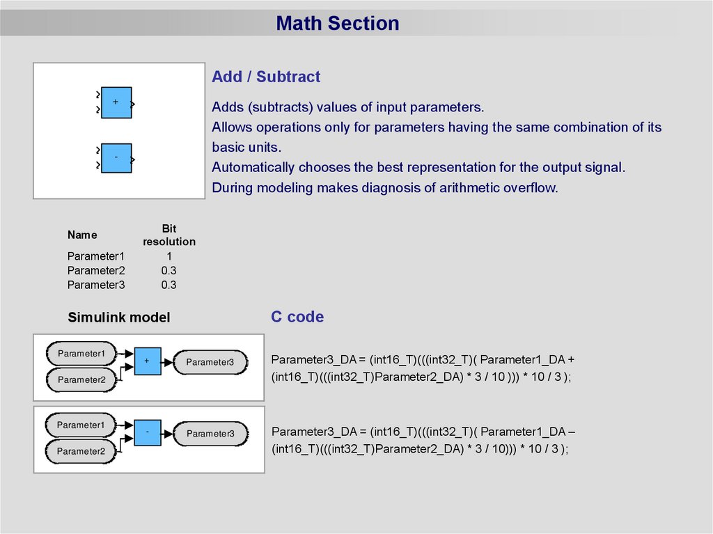
Math SectionAdd / Subtract
+
Adds (subtracts) values of input parameters.
Allows operations only for parameters having the same combination of its
basic units.
Automatically chooses the best representation for the output signal.
During modeling makes diagnosis of arithmetic overflow.
-
Name
Parameter1
Parameter2
Parameter3
Bit
resolution
1
0.3
0.3
C code
Simulink model
Parameter1
+
Parameter3
-
Parameter3
Parameter2
Parameter1
Parameter2
Parameter3_DA = (int16_T)(((int32_T)( Parameter1_DA +
(int16_T)(((int32_T)Parameter2_DA) * 3 / 10 ))) * 10 / 3 );
Parameter3_DA = (int16_T)(((int32_T)( Parameter1_DA –
(int16_T)(((int32_T)Parameter2_DA) * 3 / 10))) * 10 / 3 );
8.
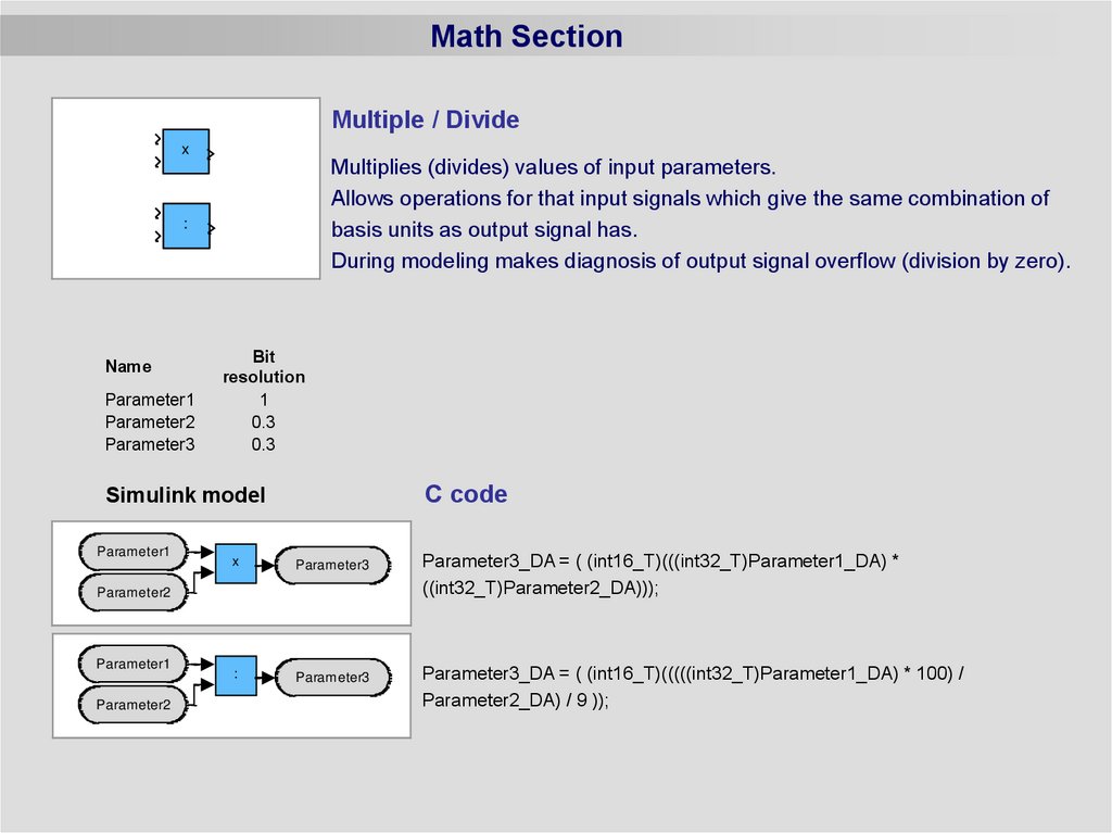
Math SectionMultiple / Divide
x
Multiplies (divides) values of input parameters.
Allows operations for that input signals which give the same combination of
basis units as output signal has.
During modeling makes diagnosis of output signal overflow (division by zero).
:
Name
Parameter1
Parameter2
Parameter3
Bit
resolution
1
0.3
0.3
C code
Simulink model
Parameter1
x
Parameter3
Parameter3_DA = ( (int16_T)(((int32_T)Parameter1_DA) *
((int32_T)Parameter2_DA)));
:
Parameter3
Parameter3_DA = ( (int16_T)(((((int32_T)Parameter1_DA) * 100) /
Parameter2_DA) / 9 ));
Parameter2
Parameter1
Parameter2
9.
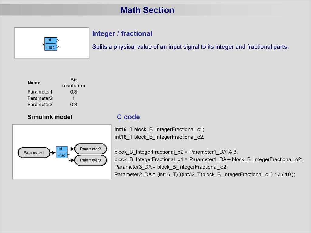
Math SectionInteger / fractional
Int
Splits a physical value of an input signal to its integer and fractional parts.
Frac
Bit
resolution
0.3
1
0.3
Name
Parameter1
Parameter2
Parameter3
C code
Simulink model
int16_T block_B_IntegerFractional_o1;
int16_T block_B_IntegerFractional_o2;
Int
Parameter1
Parameter2
Frac
Parameter3
block_B_IntegerFractional_o2 = Parameter1_DA % 3;
block_B_IntegerFractional_o1 = Parameter1_DA – block_B_IntegerFractional_o2;
Parameter3_DA = block_B_IntegerFractional_o2;
Parameter2_DA = (int16_T)(((int32_T)block_B_IntegerFractional_o1) * 3 / 10 );
10.
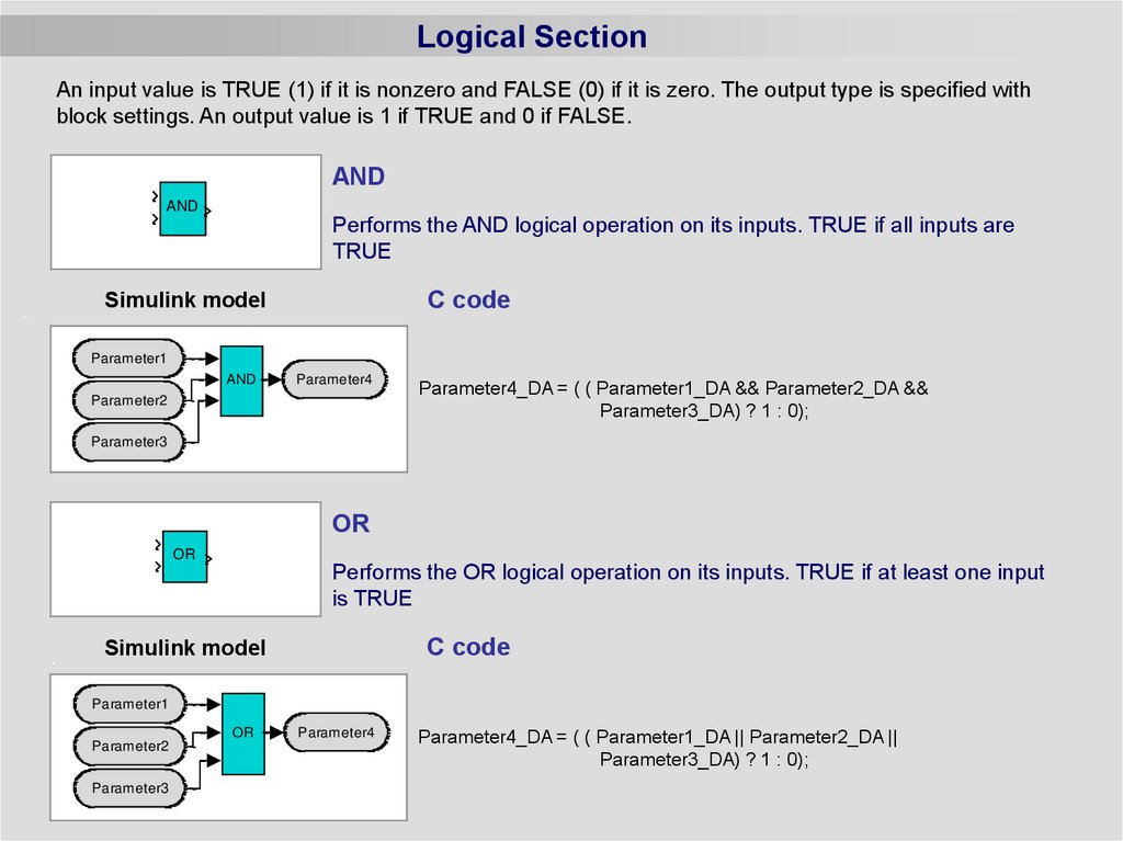
Logical SectionAn input value is TRUE (1) if it is nonzero and FALSE (0) if it is zero. The output type is specified with
block settings. An output value is 1 if TRUE and 0 if FALSE.
AND
AND
Performs the AND logical operation on its inputs. TRUE if all inputs are
TRUE
C code
Simulink model
Parameter1
AND
Parameter4
Parameter2
Parameter4_DA = ( ( Parameter1_DA && Parameter2_DA &&
Parameter3_DA) ? 1 : 0);
Parameter3
OR
OR
Performs the OR logical operation on its inputs. TRUE if at least one input
is TRUE
C code
Simulink model
Parameter1
OR
Parameter2
Parameter3
Parameter4
Parameter4_DA = ( ( Parameter1_DA || Parameter2_DA ||
Parameter3_DA) ? 1 : 0);
11.
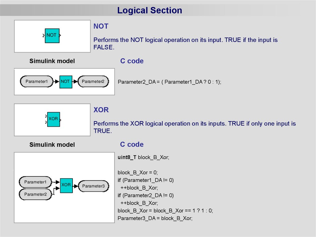
Logical SectionNOT
NOT
Performs the NOT logical operation on its input. TRUE if the input is
FALSE.
C code
Simulink model
Parameter1
NOT
Parameter2
Parameter2_DA = ( Parameter1_DA ? 0 : 1);
XOR
XOR
Performs the XOR logical operation on its inputs. TRUE if only one input is
TRUE.
C code
Simulink model
uint8_T block_B_Xor;
Parameter1
Parameter2
XOR
Parameter3
block_B_Xor = 0;
if (Parameter1_DA != 0)
++block_B_Xor;
if (Parameter2_DA != 0)
++block_B_Xor;
block_B_Xor = block_B_Xor == 1 ? 1 : 0;
Parameter3_DA = block_B_Xor;
12.
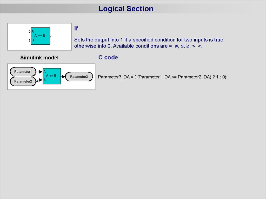
Logical SectionIf
A
A == B
Sets the output into 1 if a specified condition for two inputs is true
otherwise into 0. Available conditions are =, ≠, ≤, ≥, <, >.
B
C code
Simulink model
Parameter1
A
A <= B
Parameter2
B
Parameter3
Parameter3_DA = ( (Parameter1_DA <= Parameter2_DA) ? 1 : 0);
13.
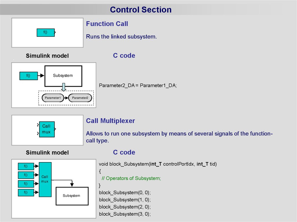
Control SectionFunction Call
f()
Runs the linked subsystem.
C code
Simulink model
f()
Subsystem
Parameter2_DA = Parameter1_DA;
Parameter1
Parameter2
Call Multiplexer
Call
mux
Allows to run one subsystem by means of several signals of the functioncall type.
Simulink model
f()
f()
f()
Call
mux
f()
Subsystem
C code
void block_Subsystem(int_T controlPortIdx, int_T tid)
{
// Operators of Subsystem;
}
block_Subsystem(0, 0);
block_Subsystem(1, 0);
block_Subsystem(2, 0);
block_Subsystem(3, 0);
14.
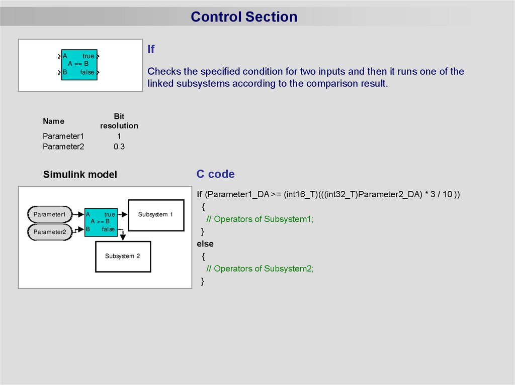
Control SectionIf
A
true
A == B
B
false
Checks the specified condition for two inputs and then it runs one of the
linked subsystems according to the comparison result.
Bit
resolution
1
0.3
Name
Parameter1
Parameter2
C code
Simulink model
Parameter1
Parameter2
A
true
A >= B
B
false
Subsystem 1
Subsystem 2
if (Parameter1_DA >= (int16_T)(((int32_T)Parameter2_DA) * 3 / 10 ))
{
// Operators of Subsystem1;
}
else
{
// Operators of Subsystem2;
}
15.
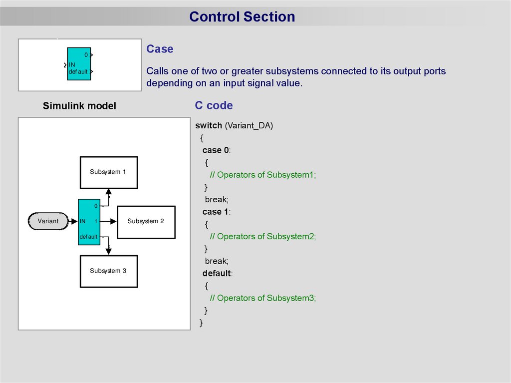
Control SectionCase
0
IN
def ault
Calls one of two or greater subsystems connected to its output ports
depending on an input signal value.
C code
Simulink model
Subsystem 1
0
Variant
IN
1
def ault
Subsystem 3
Subsystem 2
switch (Variant_DA)
{
case 0:
{
// Operators of Subsystem1;
}
break;
case 1:
{
// Operators of Subsystem2;
}
break;
default:
{
// Operators of Subsystem3;
}
}
16.
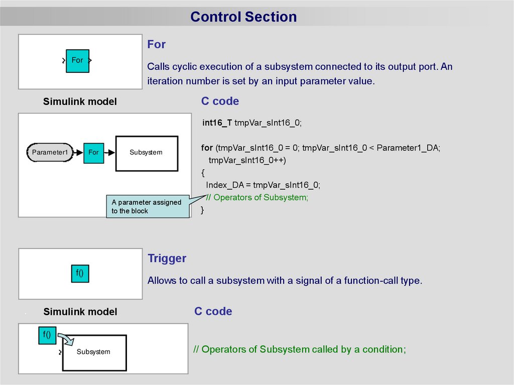
Control SectionFor
For
Calls cyclic execution of a subsystem connected to its output port. An
iteration number is set by an input parameter value.
C code
Simulink model
int16_T tmpVar_sInt16_0;
Parameter1
For
Subsystem
A parameter assigned
to the block
for (tmpVar_sInt16_0 = 0; tmpVar_sInt16_0 < Parameter1_DA;
tmpVar_sInt16_0++)
{
Index_DA = tmpVar_sInt16_0;
// Operators of Subsystem;
}
Trigger
f()
Simulink model
Allows to call a subsystem with a signal of a function-call type.
C code
f()
Subsystem
// Operators of Subsystem called by a condition;
17.
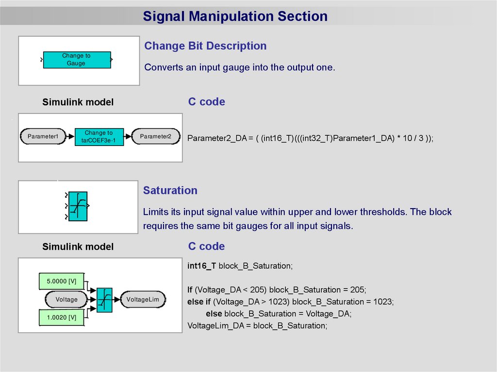
Signal Manipulation SectionChange Bit Description
Change to
Gauge
Converts an input gauge into the output one.
C code
Simulink model
Parameter1
Change to
tarCOEF3e-1
Parameter2
Parameter2_DA = ( (int16_T)(((int32_T)Parameter1_DA) * 10 / 3 ));
Saturation
Limits its input signal value within upper and lower thresholds. The block
requires the same bit gauges for all input signals.
C code
Simulink model
int16_T block_B_Saturation;
5.0000 [V]
Voltage
1.0020 [V]
VoltageLim
If (Voltage_DA < 205) block_B_Saturation = 205;
else if (Voltage_DA > 1023) block_B_Saturation = 1023;
else block_B_Saturation = Voltage_DA;
VoltageLim_DA = block_B_Saturation;
18.
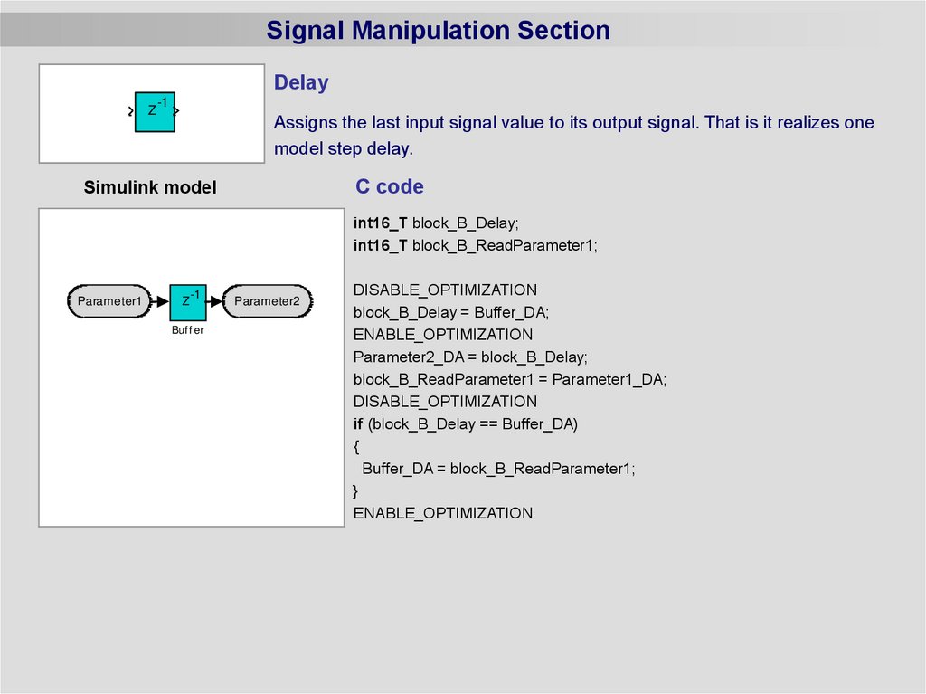
Signal Manipulation SectionDelay
Z
-1
Assigns the last input signal value to its output signal. That is it realizes one
model step delay.
C code
Simulink model
int16_T block_B_Delay;
int16_T block_B_ReadParameter1;
Parameter1
Z
-1
Buf f er
Parameter2
DISABLE_OPTIMIZATION
block_B_Delay = Buffer_DA;
ENABLE_OPTIMIZATION
Parameter2_DA = block_B_Delay;
block_B_ReadParameter1 = Parameter1_DA;
DISABLE_OPTIMIZATION
if (block_B_Delay == Buffer_DA)
{
Buffer_DA = block_B_ReadParameter1;
}
ENABLE_OPTIMIZATION
19.
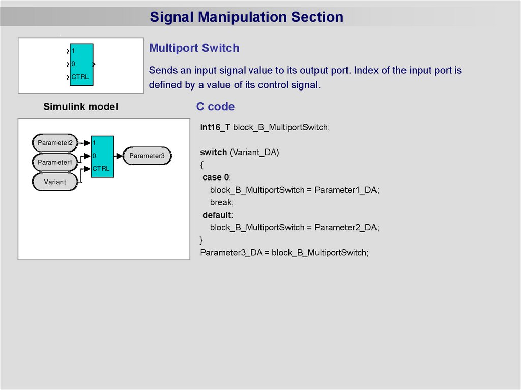
Signal Manipulation SectionMultiport Switch
1
0
Sends an input signal value to its output port. Index of the input port is
defined by a value of its control signal.
CTRL
C code
Simulink model
int16_T block_B_MultiportSwitch;
Parameter2
1
0
Parameter1
CTRL
Variant
Parameter3
switch (Variant_DA)
{
case 0:
block_B_MultiportSwitch = Parameter1_DA;
break;
default:
block_B_MultiportSwitch = Parameter2_DA;
}
Parameter3_DA = block_B_MultiportSwitch;
20.
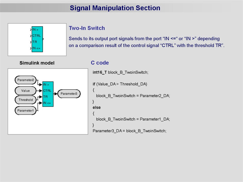
Signal Manipulation SectionTwo-In Switch
IN >
CTRL
Sends to its output port signals from the port “IN <=“ or “IN >” depending
on a comparison result of the control signal “CTRL” with the threshold TR”.
TR
IN <=
C code
Simulink model
int16_T block_B_TwoinSwitch;
Parameter2
IN >
Value
CTRL
Parameter3
TR
Threshold
IN <=
Parameter1
if (Value_DA > Threshold_DA)
{
block_B_TwoinSwitch = Parameter2_DA;
}
else
{
block_B_TwoinSwitch = Parameter1_DA;
}
Parameter3_DA = block_B_TwoinSwitch;
21.
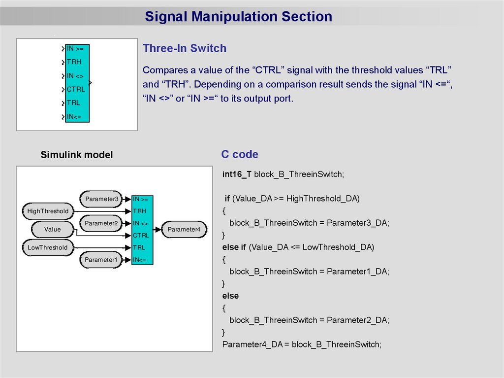
Signal Manipulation SectionThree-In Switch
IN >=
TRH
Compares a value of the “CTRL” signal with the threshold values “TRL”
and “TRH”. Depending on a comparison result sends the signal “IN <=“,
“IN <>” or “IN >=“ to its output port.
IN <>
CTRL
TRL
IN<=
C code
Simulink model
int16_T block_B_ThreeinSwitch;
Parameter3
HighThreshold
IN >=
TRH
Parameter2
IN <>
Value
Parameter4
CTRL
LowThreshold
TRL
Parameter1
IN<=
if (Value_DA >= HighThreshold_DA)
{
block_B_ThreeinSwitch = Parameter3_DA;
}
else if (Value_DA <= LowThreshold_DA)
{
block_B_ThreeinSwitch = Parameter1_DA;
}
else
{
block_B_ThreeinSwitch = Parameter2_DA;
}
Parameter4_DA = block_B_ThreeinSwitch;
22.
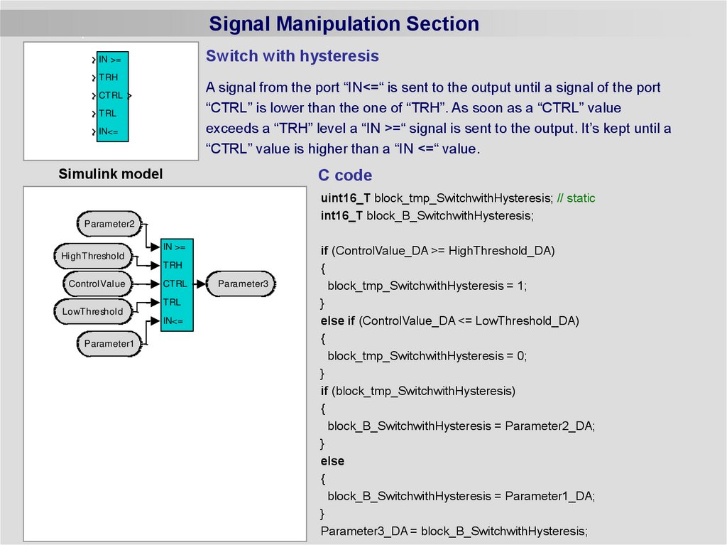
Signal Manipulation SectionSwitch with hysteresis
IN >=
TRH
A signal from the port “IN<=“ is sent to the output until a signal of the port
“CTRL” is lower than the one of “TRH”. As soon as a “CTRL” value
exceeds a “TRH” level a “IN >=“ signal is sent to the output. It’s kept until a
“CTRL” value is higher than a “IN <=“ value.
CTRL
TRL
IN<=
Simulink model
C code
uint16_T block_tmp_SwitchwithHysteresis; // static
int16_T block_B_SwitchwithHysteresis;
Parameter2
IN >=
HighThreshold
TRH
ControlValue
CTRL
TRL
LowThreshold
IN<=
Parameter1
Parameter3
if (ControlValue_DA >= HighThreshold_DA)
{
block_tmp_SwitchwithHysteresis = 1;
}
else if (ControlValue_DA <= LowThreshold_DA)
{
block_tmp_SwitchwithHysteresis = 0;
}
if (block_tmp_SwitchwithHysteresis)
{
block_B_SwitchwithHysteresis = Parameter2_DA;
}
else
{
block_B_SwitchwithHysteresis = Parameter1_DA;
}
Parameter3_DA = block_B_SwitchwithHysteresis;
23.
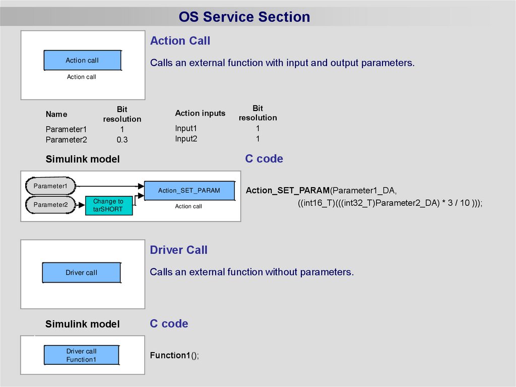
OS Service SectionAction Call
Action call
Calls an external function with input and output parameters.
Action call
Bit
resolution
1
0.3
Name
Parameter1
Parameter2
Action inputs
Input1
Input2
C code
Simulink model
Parameter1
Parameter2
Action_SET_PARAM
Change to
tarSHORT
Bit
resolution
1
1
Action call
Action_SET_PARAM(Parameter1_DA,
((int16_T)(((int32_T)Parameter2_DA) * 3 / 10 )));
Driver Call
Driver call
Simulink model
Driver call
Function1
Calls an external function without parameters.
C code
Function1();
24.
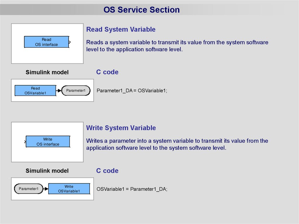
OS Service SectionRead System Variable
Read
OS interface
Reads a system variable to transmit its value from the system software
level to the application software level.
Simulink model
Read
OSVariable1
Parameter1
C code
Parameter1_DA = OSVariable1;
Write System Variable
Write
OS interface
Simulink model
Parameter1
Write
OSVariable1
Writes a parameter into a system variable to transmit its value from the
application software level to the system software level.
C code
OSVariable1 = Parameter1_DA;
25.
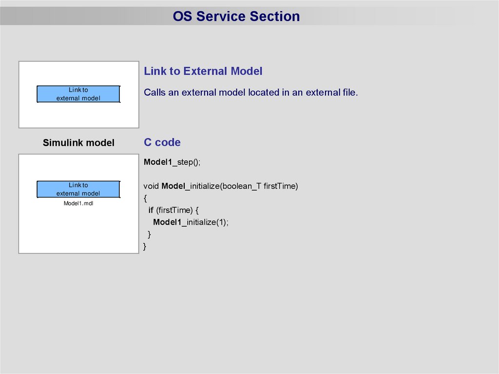
OS Service SectionLink to External Model
Link to
external model
Simulink model
Calls an external model located in an external file.
C code
Model1_step();
Link to
external model
Model1.mdl
void Model_initialize(boolean_T firstTime)
{
if (firstTime) {
Model1_initialize(1);
}
}
26.
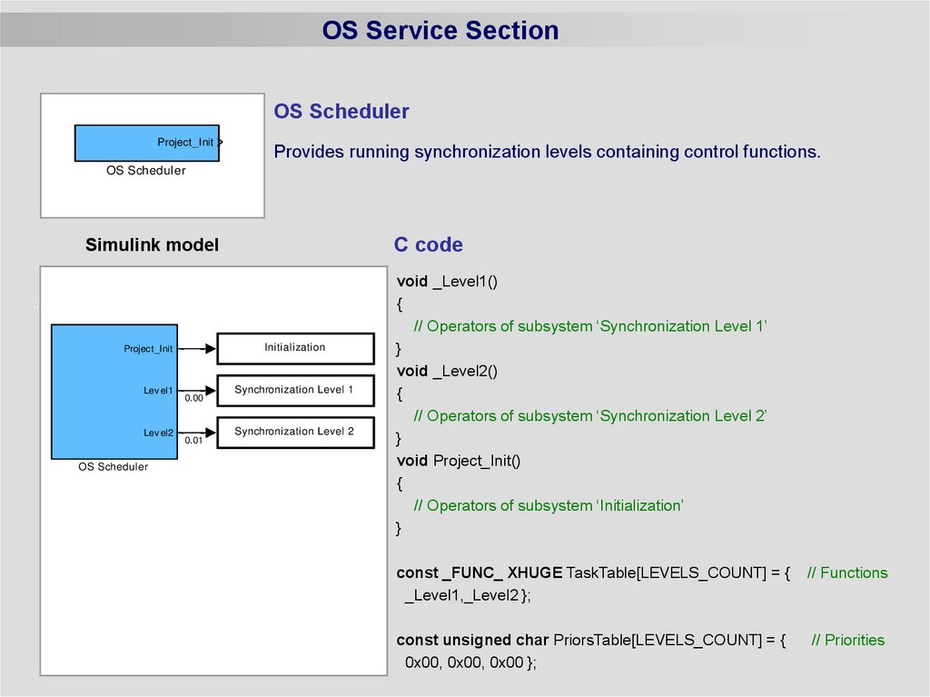
OS Service SectionOS Scheduler
Project_Init
Provides running synchronization levels containing control functions.
OS Scheduler
C code
Simulink model
Initialization
Project_Init
Lev el1
Lev el2
OS Scheduler
0.00
0.01
Synchronization Level 1
Synchronization Level 2
void _Level1()
{
// Operators of subsystem ‘Synchronization Level 1’
}
void _Level2()
{
// Operators of subsystem ‘Synchronization Level 2’
}
void Project_Init()
{
// Operators of subsystem ‘Initialization’
}
const _FUNC_ XHUGE TaskTable[LEVELS_COUNT] = {
_Level1,_Level2 };
// Functions
const unsigned char PriorsTable[LEVELS_COUNT] = {
0x00, 0x00, 0x00 };
// Priorities
27.
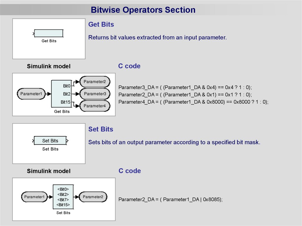
Bitwise Operators SectionGet Bits
Returns bit values extracted from an input parameter.
Get Bits
C code
Simulink model
Parameter2
Bit0
Parameter1
Bit2
Bit15
Parameter3
Parameter4
Parameter3_DA = ( (Parameter1_DA & 0x4) == 0x4 ? 1 : 0);
Parameter2_DA = ( (Parameter1_DA & 0x1) == 0x1 ? 1 : 0);
Parameter4_DA = ( (Parameter1_DA & 0x8000) == 0x8000 ? 1 : 0);
Get Bits
Set Bits
Set Bits
Sets bits of an output parameter according to a specified bit mask.
Set Bits
C code
Simulink model
Parameter1
<Bit0>
<Bit2>
<Bit7>
<Bit15>
Set Bits
Parameter2
Parameter2_DA = ( Parameter1_DA | 0x8085);
28.
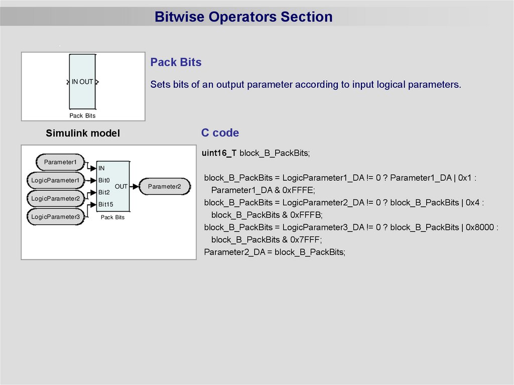
Bitwise Operators SectionPack Bits
IN OUT
Sets bits of an output parameter according to input logical parameters.
Pack Bits
C code
Simulink model
uint16_T block_B_PackBits;
Parameter1
IN
LogicParameter1
Bit0
OUT
Bit2
LogicParameter2
Bit15
LogicParameter3
Pack Bits
Parameter2
block_B_PackBits = LogicParameter1_DA != 0 ? Parameter1_DA | 0x1 :
Parameter1_DA & 0xFFFE;
block_B_PackBits = LogicParameter2_DA != 0 ? block_B_PackBits | 0x4 :
block_B_PackBits & 0xFFFB;
block_B_PackBits = LogicParameter3_DA != 0 ? block_B_PackBits | 0x8000 :
block_B_PackBits & 0x7FFF;
Parameter2_DA = block_B_PackBits;
29.
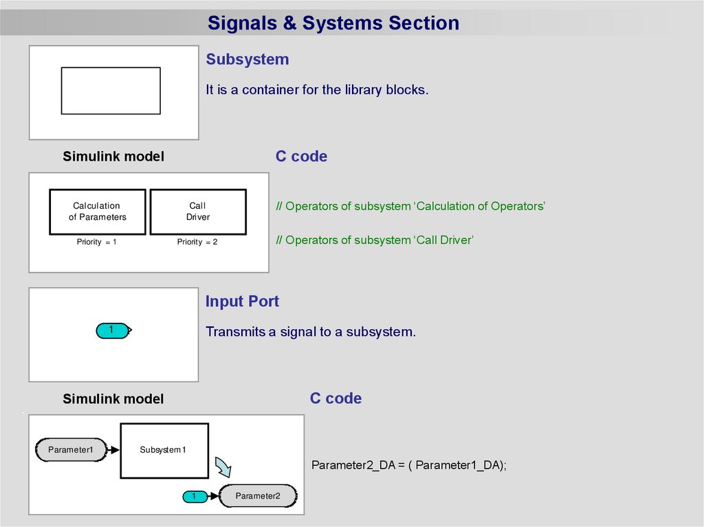
Signals & Systems SectionSubsystem
It is a container for the library blocks.
C code
Simulink model
Calculation
of Parameters
Call
Driver
Priority = 1
Priority = 2
// Operators of subsystem ‘Calculation of Operators’
// Operators of subsystem ‘Call Driver’
Input Port
1
Transmits a signal to a subsystem.
C code
Simulink model
Parameter1
Subsystem1
Parameter2_DA = ( Parameter1_DA);
1
Parameter2
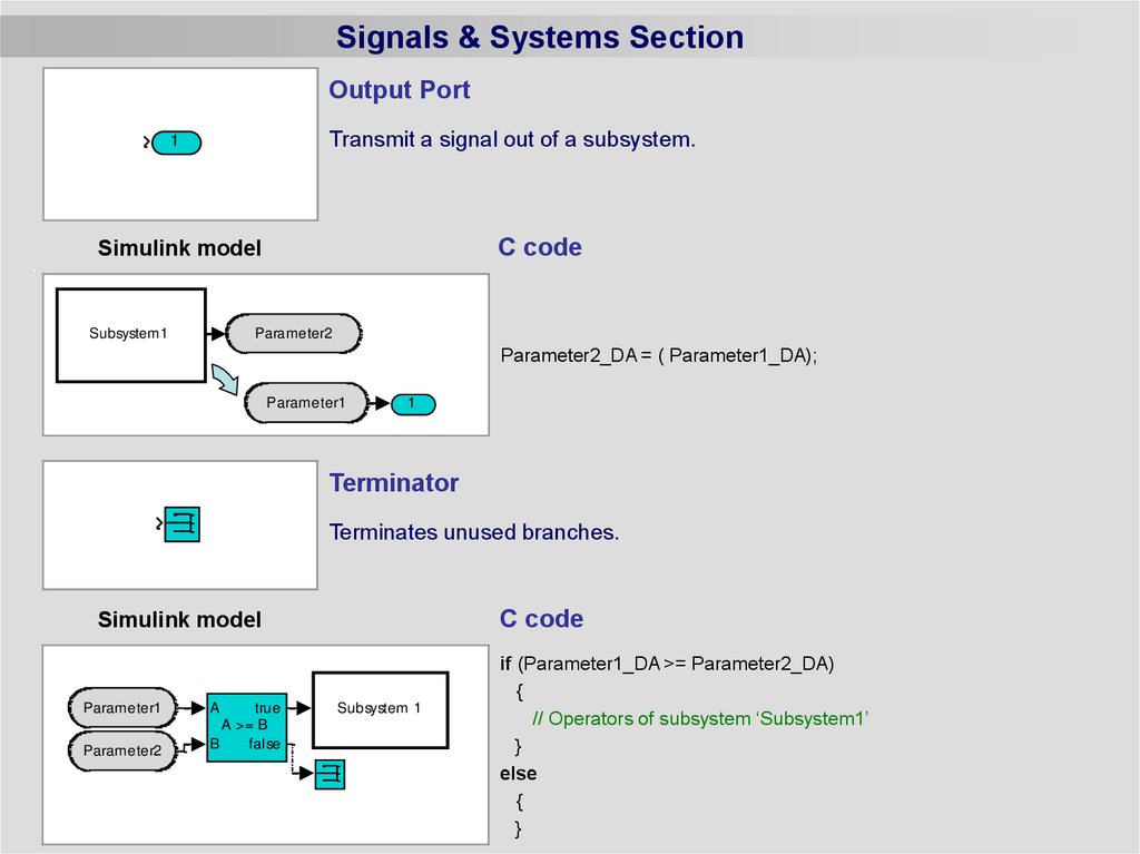
30.
Signals & Systems SectionOutput Port
Transmit a signal out of a subsystem.
1
C code
Simulink model
Subsystem1
Parameter2
Parameter2_DA = ( Parameter1_DA);
Parameter1
1
Terminator
Terminates unused branches.
C code
Simulink model
Parameter1
Parameter2
A
true
A >= B
B
false
Subsystem 1
if (Parameter1_DA >= Parameter2_DA)
{
// Operators of subsystem ‘Subsystem1’
}
else
{
}