

 Электроника
Похожие презентации:


 & Compressor Dehydrator")


On core safety system
1.
OnCore Safety SystemArchitecture, Hardware & Software
Copyright 2020 Baker Hughes Company. All rights reserved. The information contained in this document is company confidential and proprietary property of Baker
Hughes and its affiliates. It is to be used only for the benefit of Baker Hughes and may not be distributed, transmitted, reproduced, altered, or used for any purpose
without the express written consent of Baker Hughes.
2.
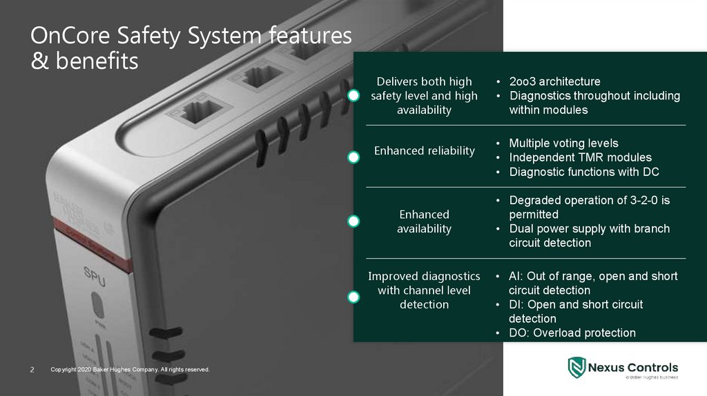
OnCore Safety System features& benefits
Delivers both high
safety level and high
availability
• 2oo3 architecture
• Diagnostics throughout including
within modules
Enhanced reliability
• Multiple voting levels
• Independent TMR modules
• Diagnostic functions with DC
Enhanced
availability
Improved diagnostics
with channel level
detection
2
Copyright 2020 Baker Hughes Company. All rights reserved.
• Degraded operation of 3-2-0 is
permitted
• Dual power supply with branch
circuit detection
• AI: Out of range, open and short
circuit detection
• DI: Open and short circuit
detection
• DO: Overload protection
3.
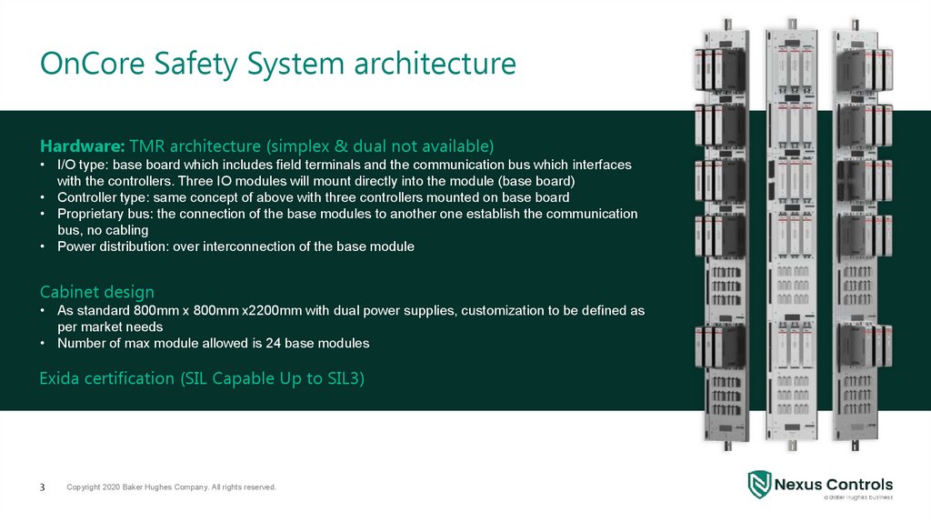
OnCore Safety System architectureHardware: TMR architecture (simplex & dual not available)
• I/O type: base board which includes field terminals and the communication bus which interfaces
with the controllers. Three IO modules will mount directly into the module (base board)
• Controller type: same concept of above with three controllers mounted on base board
• Proprietary bus: the connection of the base modules to another one establish the communication
bus, no cabling
• Power distribution: over interconnection of the base module
Cabinet design
• As standard 800mm x 800mm x2200mm with dual power supplies, customization to be defined as
per market needs
• Number of max module allowed is 24 base modules
Exida certification (SIL Capable Up to SIL3)
3
Copyright 2020 Baker Hughes Company. All rights reserved.
4.
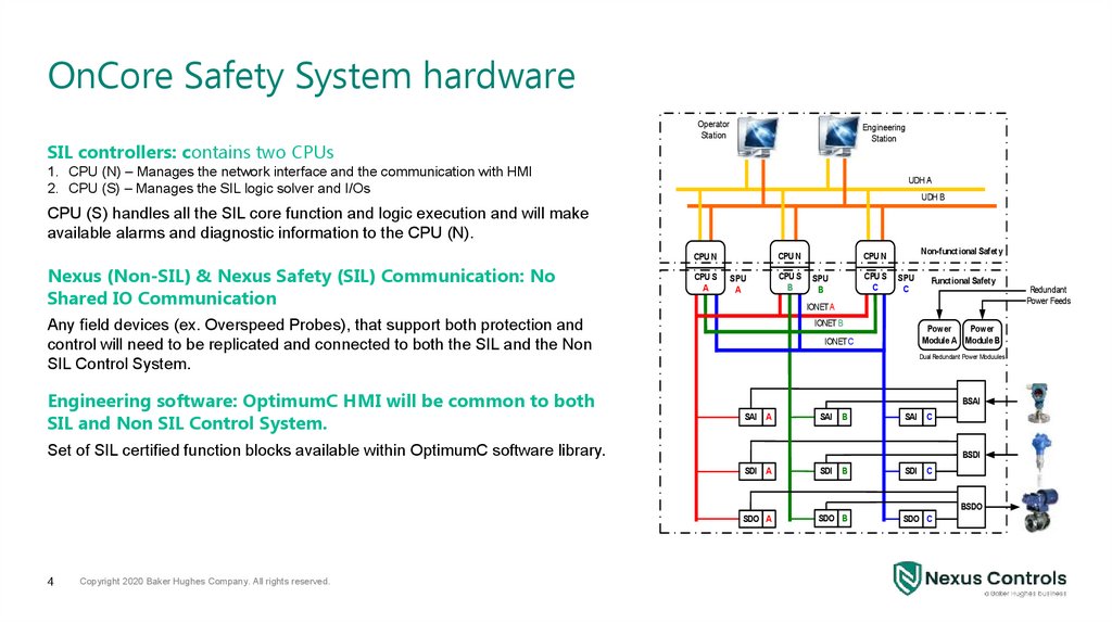
OnCore Safety System hardwareSIL controllers: contains two CPUs
Operator
Station
Engineering
Station
1. CPU (N) – Manages the network interface and the communication with HMI
2. CPU (S) – Manages the SIL logic solver and I/Os
UDH A
UDH B
CPU (S) handles all the SIL core function and logic execution and will make
available alarms and diagnostic information to the CPU (N).
CPU N
CPU N
Nexus (Non-SIL) & Nexus Safety (SIL) Communication: No
Shared IO Communication
CPU S
A
SPU
A
SPU
B
CPU S
C
SPU
C
Functional Safety
IONET A
IONET B
Any field devices (ex. Overspeed Probes), that support both protection and
control will need to be replicated and connected to both the SIL and the Non
SIL Control System.
Engineering software: OptimumC HMI will be common to both
SIL and Non SIL Control System.
CPU S
B
Non-functional Safety
CPU N
Power
Power
Module A Module B
IONET C
Dual Redundant Power Moduules
BSAI
SAI A
SAI B
SAI C
Set of SIL certified function blocks available within OptimumC software library.
BSDI
SDI A
SDI B
SDI
C
SDO A
SDO B
SDO C
BSDO
4
Copyright 2020 Baker Hughes Company. All rights reserved.
Redundant
Power Feeds
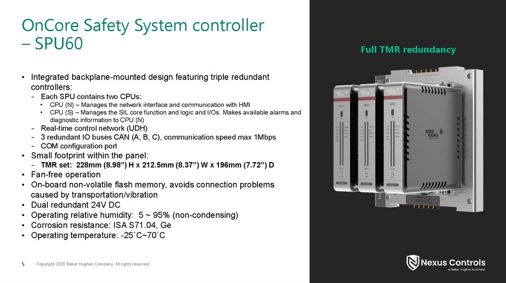
5.
OnCore Safety System controller– SPU60
• Integrated backplane-mounted design featuring triple redundant
controllers:
– Each SPU contains two CPUs:
CPU (N) – Manages the network interface and communication with HMI
CPU (S) – Manages the SIL core function and logic and I/Os. Makes available alarms and
diagnostic information to CPU (N)
– Real-time control network (UDH)
– 3 redundant IO buses CAN (A, B, C), communication speed max 1Mbps
– COM configuration port
• Small footprint within the panel:
– TMR set: 228mm (8.98”) H x 212.5mm (8.37”) W x 196mm (7.72”) D
• Fan-free operation
• On-board non-volatile flash memory, avoids connection problems
caused by transportation/vibration
• Dual redundant 24V DC
• Operating relative humidity: 5 ~ 95% (non-condensing)
• Corrosion resistance: ISA S71.04, Ge
• Operating temperature: -25˚C~70˚C
5
Copyright 2020 Baker Hughes Company. All rights reserved.
Full TMR redundancy
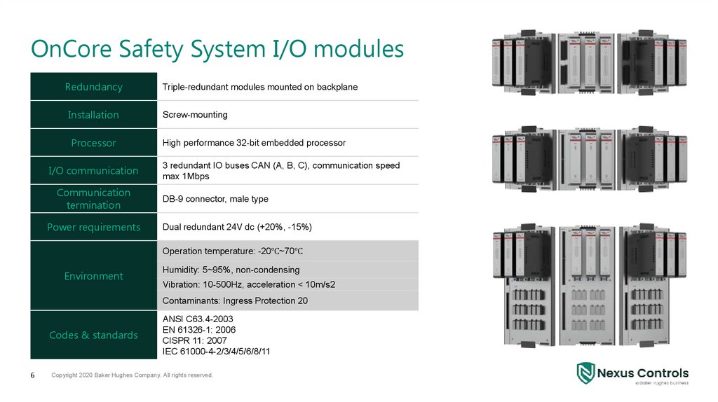
6.
OnCore Safety System I/O modulesRedundancy
Installation
Processor
I/O communication
Communication
termination
Power requirements
Triple-redundant modules mounted on backplane
Screw-mounting
High performance 32-bit embedded processor
3 redundant IO buses CAN (A, B, C), communication speed
max 1Mbps
DB-9 connector, male type
Dual redundant 24V dc (+20%, -15%)
Operation temperature: -20℃~70℃
Environment
Humidity: 5~95%, non-condensing
Vibration: 10-500Hz, acceleration < 10m/s2
Contaminants: Ingress Protection 20
Codes & standards
6
ANSI C63.4-2003
EN 61326-1: 2006
CISPR 11: 2007
IEC 61000-4-2/3/4/5/6/8/11
Copyright 2020 Baker Hughes Company. All rights reserved.
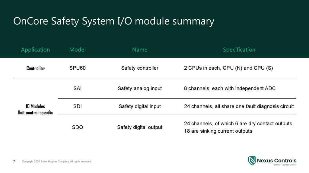
7.
OnCore Safety System I/O module summaryApplication
Model
Name
Controller
SPU60
Safety controller
2 CPUs in each, CPU (N) and CPU (S)
SAI
Safety analog input
8 channels, each with independent ADC
SDI
Safety digital input
24 channels, all share one fault diagnosis circuit
SDO
Safety digital output
24 channels, of which 6 are dry contact outputs,
18 are sinking current outputs
IO Modules
Unit control specific
7
Copyright 2020 Baker Hughes Company. All rights reserved.
Specification
8.
9.
Backup9
Copyright 2020 Baker Hughes Company. All rights reserved.
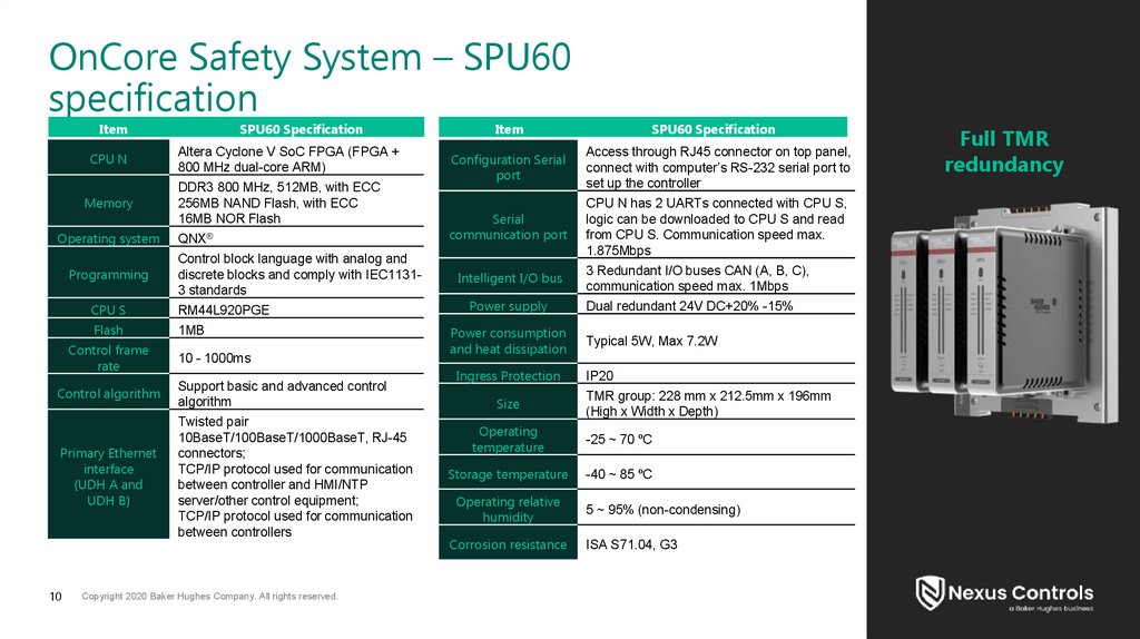
10.
OnCore Safety System – SPU60specification
Item
CPU N
Memory
Operating system
Programming
SPU60 Specification
Altera Cyclone V SoC FPGA (FPGA +
800 MHz dual-core ARM)
DDR3 800 MHz, 512MB, with ECC
256MB NAND Flash, with ECC
16MB NOR Flash
QNX®
Control block language with analog and
discrete blocks and comply with IEC11313 standards
CPU S
RM44L920PGE
Flash
1MB
Control frame
rate
10 - 1000ms
Control algorithm
Support basic and advanced control
algorithm
Primary Ethernet
interface
(UDH A and
UDH B)
Twisted pair
10BaseT/100BaseT/1000BaseT, RJ-45
connectors;
TCP/IP protocol used for communication
between controller and HMI/NTP
server/other control equipment;
TCP/IP protocol used for communication
between controllers
10
Copyright 2020 Baker Hughes Company. All rights reserved.
Item
SPU60 Specification
Configuration Serial
port
Access through RJ45 connector on top panel,
connect with computer’s RS-232 serial port to
set up the controller
Serial
communication port
CPU N has 2 UARTs connected with CPU S,
logic can be downloaded to CPU S and read
from CPU S. Communication speed max.
1.875Mbps
Intelligent I/O bus
Power supply
Power consumption
and heat dissipation
Ingress Protection
Size
3 Redundant I/O buses CAN (A, B, C),
communication speed max. 1Mbps
Dual redundant 24V DC+20% -15%
Typical 5W, Max 7.2W
IP20
TMR group: 228 mm x 212.5mm x 196mm
(High x Width x Depth)
Operating
temperature
-25 ~ 70 ºC
Storage temperature
-40 ~ 85 ºC
Operating relative
humidity
Corrosion resistance
5 ~ 95% (non-condensing)
ISA S71.04, G3
Full TMR
redundancy
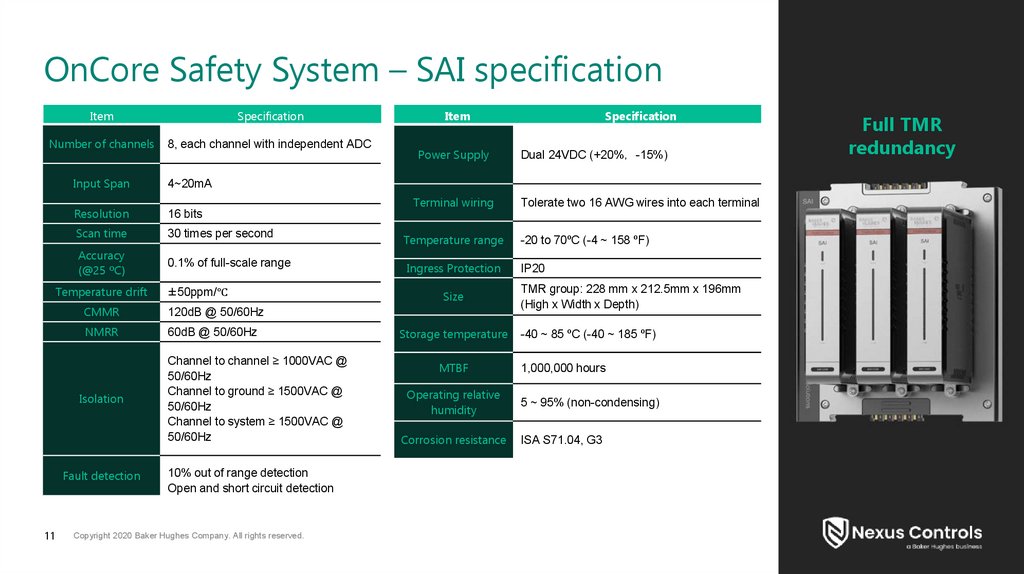
11.
OnCore Safety System – SAI specificationItem
Specification
Number of channels
8, each channel with independent ADC
Power Supply
Specification
Dual 24VDC (+20% -15%)
Input Span
4~20mA
Resolution
16 bits
Scan time
30 times per second
Temperature range
-20 to 70ºC (-4 ~ 158 ºF)
Accuracy
(@25 ºC)
0.1% of full-scale range
Ingress Protection
IP20
Temperature drift
Terminal wiring
±50ppm/℃
CMMR
120dB @ 50/60Hz
NMRR
60dB @ 50/60Hz
Isolation
Fault detection
11
Item
Channel to channel ≥ 1000VAC @
50/60Hz
Channel to ground ≥ 1500VAC @
50/60Hz
Channel to system ≥ 1500VAC @
50/60Hz
10% out of range detection
Open and short circuit detection
Copyright 2020 Baker Hughes Company. All rights reserved.
Size
Storage temperature
MTBF
Operating relative
humidity
Corrosion resistance
Tolerate two 16 AWG wires into each terminal
TMR group: 228 mm x 212.5mm x 196mm
(High x Width x Depth)
-40 ~ 85 ºC (-40 ~ 185 ºF)
1,000,000 hours
5 ~ 95% (non-condensing)
ISA S71.04, G3
Full TMR
redundancy
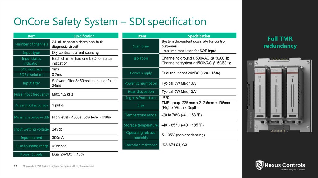
12.
OnCore Safety System – SDI specificationItem
Number of channels
Input type
Input status
indication
SOE accuracy
SOE resolution
Input filter
Specification
24, all channels share one fault
diagnosis circuit
Each channel has one LED for status
indication
1ms
0.2ms
Software filter,3~50ms tunable, default
24ms
1 pulse
Minimum pulse width High level - 420us; Low level - 410us
Input wetting voltage 24Vdc
Input current
300mA
Pulse counting range 0~65535
Power Supply
12
Scan time
Dry contact, current sourcing
Pulse input frequency Max. 1.2 kHz
Pulse input accuracy
Item
Dual 24VDC ±10%
Copyright 2020 Baker Hughes Company. All rights reserved.
Isolation
Power supply
Specification
System dependent scan rate for control
purposes
1ms time resolution for SOE input
Channel to ground ≥ 500VAC @ 50/60Hz
Channel to system ≥ 1500VAC @ 50/60Hz
Dual redundant 24VDC (+20~-15%)
Power consumption
Typical 5W Max 10W
Heat dissipation
Typical 5W Max 10W
Ingress Protection
Size
IP20
TMR group: 228 mm x 212.5mm x 196mm
(High x Width x Depth)
Temperature range
-20 to 70ºC (-4 ~ 158 ºF)
Storage temperature
-40 ~ 85 ºC (-40 ~ 185 ºF)
Operating relative
humidity
5 ~ 95% (non-condensing)
Corrosion resistance
ISA S71.04, G3
Full TMR
redundancy
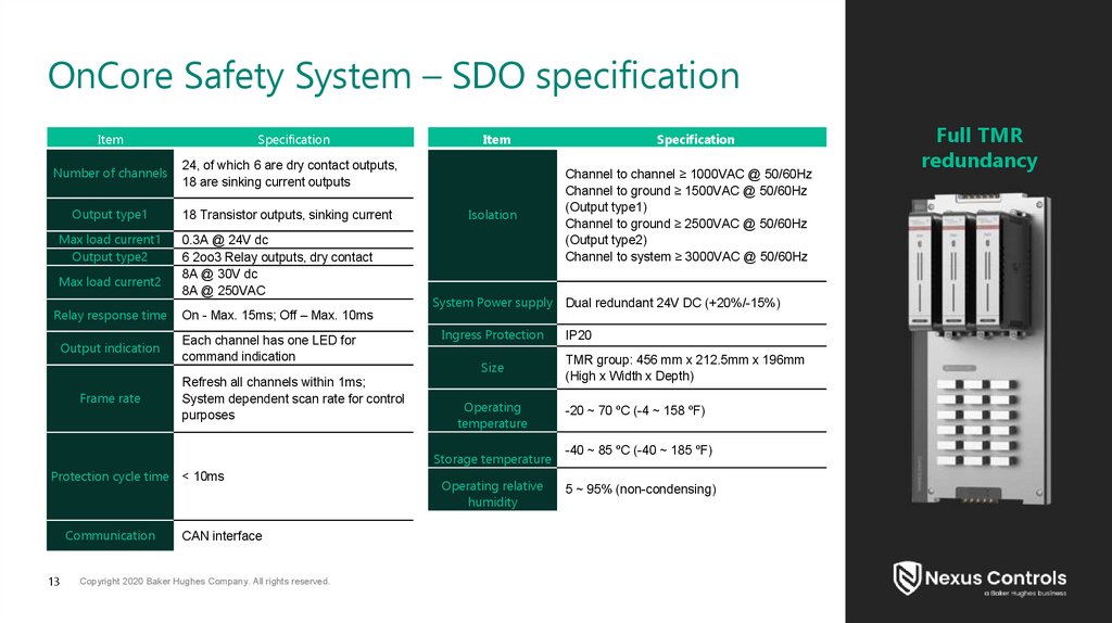
13.
OnCore Safety System – SDO specificationItem
Specification
Number of channels
24, of which 6 are dry contact outputs,
18 are sinking current outputs
Output type1
18 Transistor outputs, sinking current
Max load current1
Output type2
Max load current2
Relay response time
Output indication
Frame rate
0.3A @ 24V dc
6 2oo3 Relay outputs, dry contact
8A @ 30V dc
8A @ 250VAC
On - Max. 15ms; Off – Max. 10ms
Each channel has one LED for
command indication
Refresh all channels within 1ms;
System dependent scan rate for control
purposes
Item
Isolation
System Power supply
Ingress Protection
Size
Operating
temperature
Storage temperature
Protection cycle time < 10ms
Communication
13
CAN interface
Copyright 2020 Baker Hughes Company. All rights reserved.
Operating relative
humidity
Specification
Channel to channel ≥ 1000VAC @ 50/60Hz
Channel to ground ≥ 1500VAC @ 50/60Hz
(Output type1)
Channel to ground ≥ 2500VAC @ 50/60Hz
(Output type2)
Channel to system ≥ 3000VAC @ 50/60Hz
Dual redundant 24V DC (+20%/-15%)
IP20
TMR group: 456 mm x 212.5mm x 196mm
(High x Width x Depth)
-20 ~ 70 ºC (-4 ~ 158 ºF)
-40 ~ 85 ºC (-40 ~ 185 ºF)
5 ~ 95% (non-condensing)
Full TMR
redundancy