


")
")
")


 Introduction")
 Introduction")
 Introduction")
 How ? (1/3)")
 How ? (2/3)")
 How ? (3/3)")
")
")
")
")
")
")
")
")
")
")
")
")


 Механика
Похожие презентации:


 - Technical Highlights")


TE transmissions training program
1. TE transmissions training program
Spicer Off-Highway Products DivisionTE transmissions training program
Basic converter/transmission theory
TE transmissions
TE 13/17/32 transmissions
APC200 controller
TE transmission field experience
2. Basic connverter /transmission theory
Spicer Off-Highway Products DivisionBasic connverter /transmission theory
movie
3. TE transmissions
Spicer Off-Highway Products DivisionTE transmissions
Electronic controlled modulation
Clutch overlap control
Inching control
4.
Spicer Off-Highway Products DivisionController
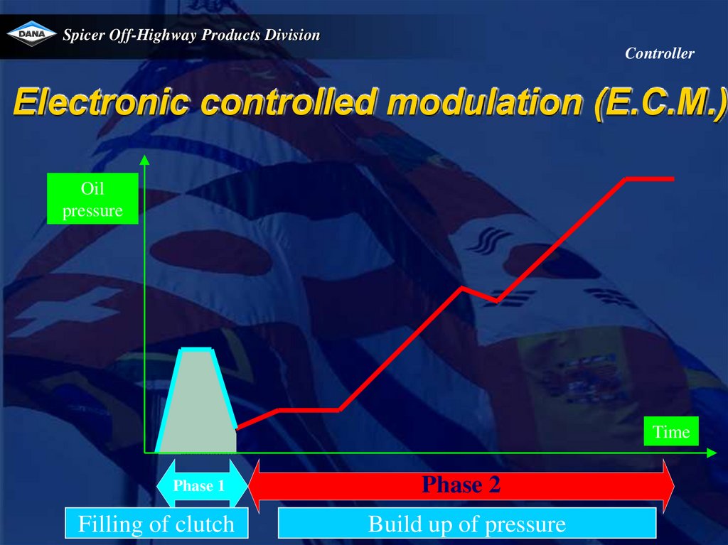
Electronic controlled modulation (E.C.M.)
Oil
pressure
Time
Phase 1
Filling of clutch
Phase 2
Build up of pressure
5.
Spicer Off-Highway Products DivisionController
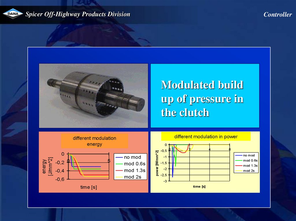
Electronic controlled modulation (E.C.M.)
Modulated build
up of pressure in
the clutch
2,00E+06
1,80E+06
1,60E+06
1,40E+06
1,20E+06
1,00E+06
8,00E+05
6,00E+05
4,00E+05
2,00E+05
0,00E+00
Different modulation : vehspeed [m/s]
ifo time [s]
no mod
mod 0.6s
mod 1.3s
mod 2s
0
1
2
3
time [s]
4
5
vehspeed
[m/s]
pressure [Pa]
Different
modulation
: pressure
[Pa]toifo
time [s]
different
modulation
pressure
time.
4
2
0
-2 0
5
time [s]
no mod
mod 0.6s
mod 1.3s
mod 2s
6.
Spicer Off-Highway Products DivisionController
Modulated build
up of pressure in
the clutch
Different modulation : power [W/mm^2] ifo time [s]
different modulation in power
Different
modulation
: energy
different
modulation
[J/mm^2]
ifo time [s]
energy
-0,2 0
5
-0,4
-0,6
no mod
mod 0.6s
mod 1.3s
mod 2s
power [W/mm^2]
energy
[J/mm^2]
0
0
-0,5 0
2
4
no mod
-1
mod 0.6s
-1,5
mod 1.3s
-2
mod 2s
-2,5
-3
time [s]
6
time [s]
7.
Spicer Off-Highway Products DivisionController
Overlap control
Oil
pressure
Pressure
phase out in
clutch 1
“overlap”
Pressure
phase in in
clutch 2
Time
8.
Spicer Off-Highway Products DivisionController
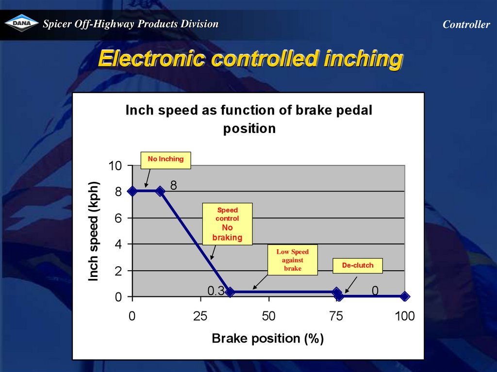
Electronic controlled inching
Inch speed as function of brake pedal
position
No Inching
Inch speed (kph)
10
8
8
Speed
control
6
No
braking
4
Low Speed
against
brake
2
De-clutch
0.3
0
0
25
0
50
Brake position (%)
75
100
9. TE13/17 transmission
Spicer Off-Highway Products DivisionTE13/17 transmission
10.
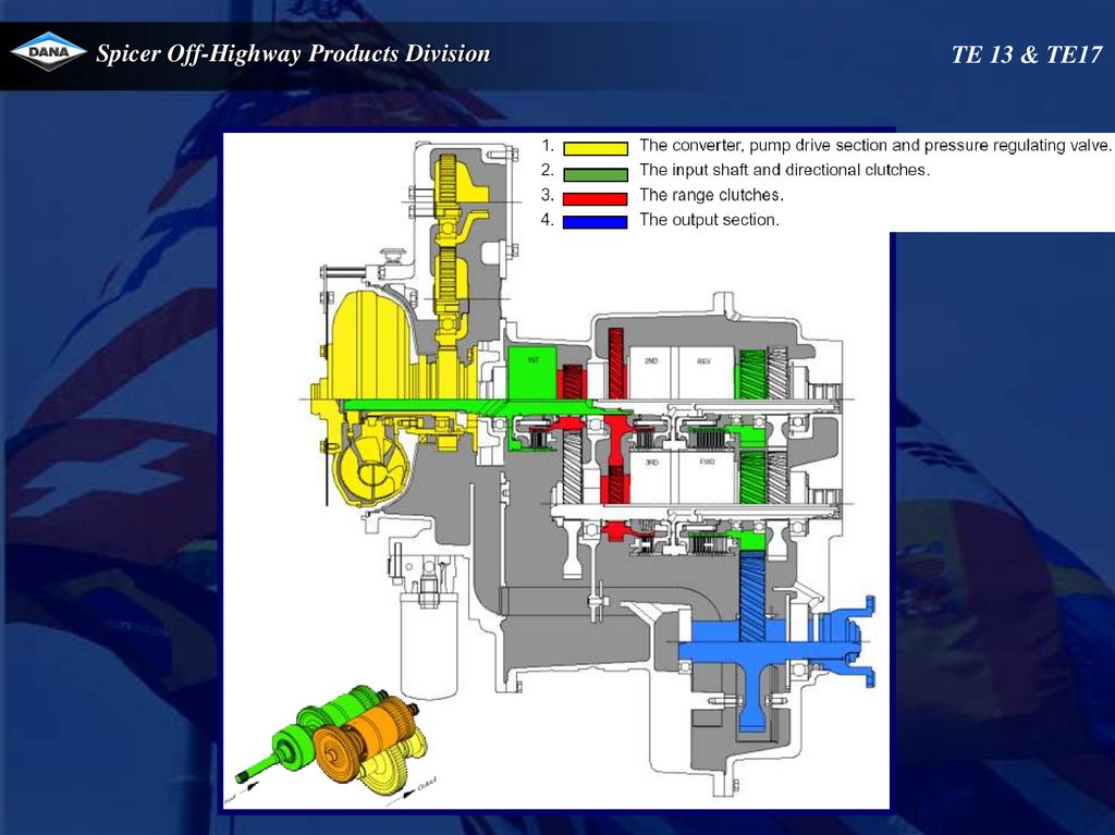
Spicer Off-Highway Products DivisionTE 13 & TE17
11.
Spicer Off-Highway Products DivisionTE 13 & TE17
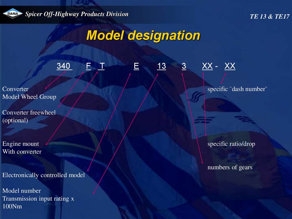
Model designation
340
Converter
Model Wheel Group
F
T
E
13
3
XX - XX
specific ¨dash number¨
Converter freewheel
(optional)
Engine mount
With converter
specific ratio/drop
numbers of gears
Electronically controlled model
Model number
Transmission input rating x
100Nm
12.
Spicer Off-Highway Products DivisionTechnical specifications
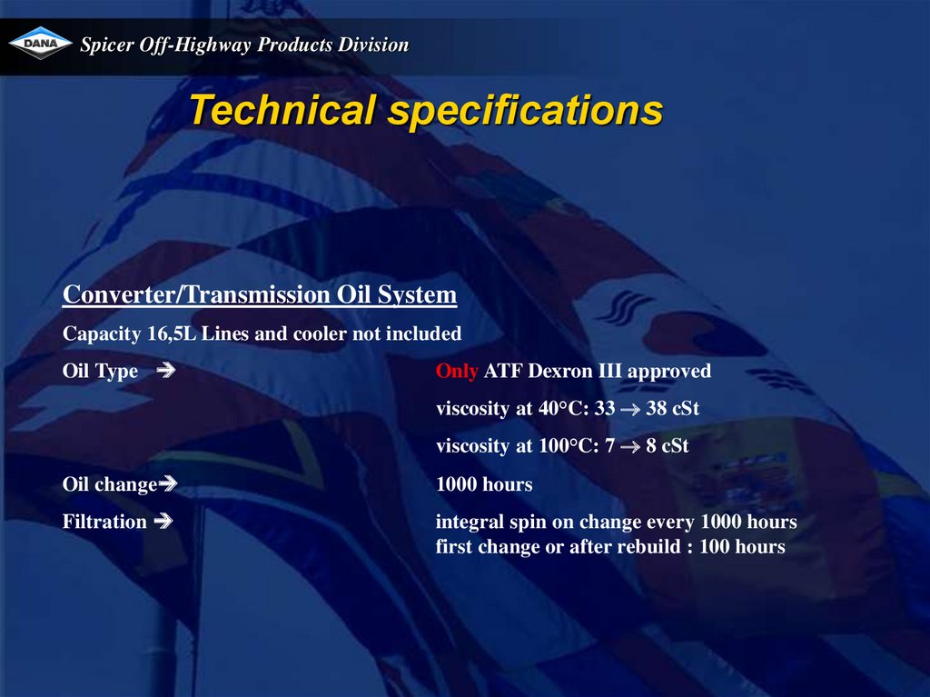
Converter/Transmission Oil System
Capacity 16,5L Lines and cooler not included
Oil Type
Only ATF Dexron III approved
viscosity at 40°C: 33 38 cSt
viscosity at 100°C: 7 8 cSt
Oil change
1000 hours
Filtration
integral spin on change every 1000 hours
first change or after rebuild : 100 hours
13.
Spicer Off-Highway Products DivisionTE 13 & TE17
Technical specifications
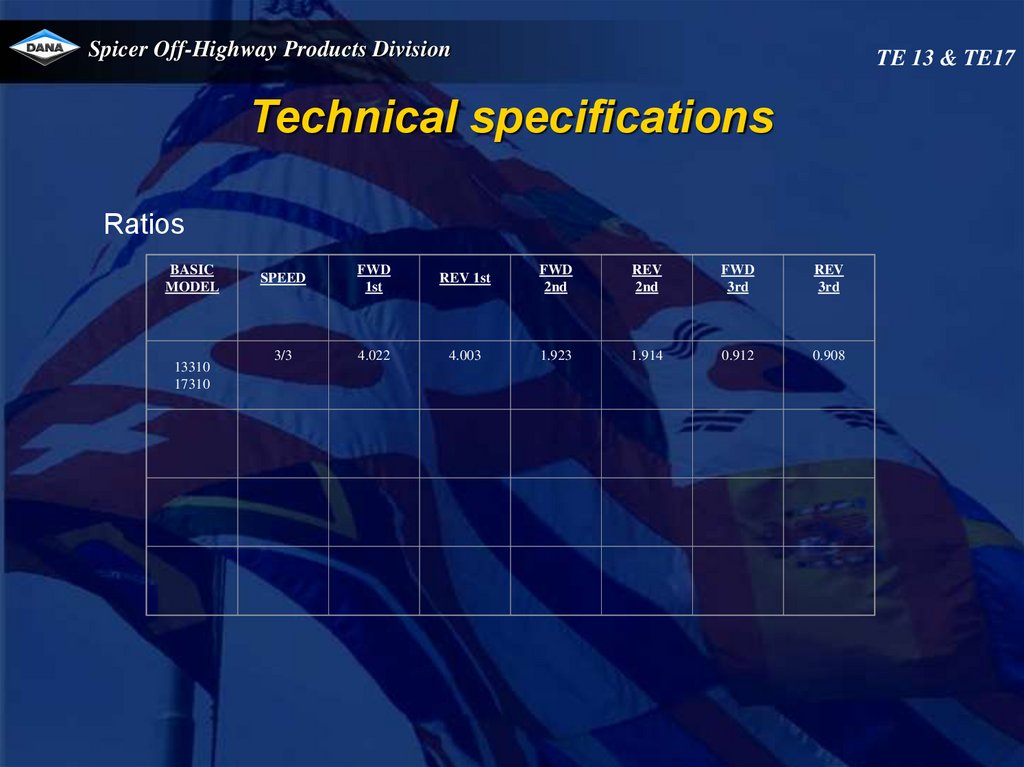
Ratios
BASIC
MODEL
13310
17310
SPEED
FWD
1st
REV 1st
FWD
2nd
REV
2nd
FWD
3rd
REV
3rd
3/3
4.022
4.003
1.923
1.914
0.912
0.908
14.
Spicer Off-Highway Products DivisionTE 13 & TE17
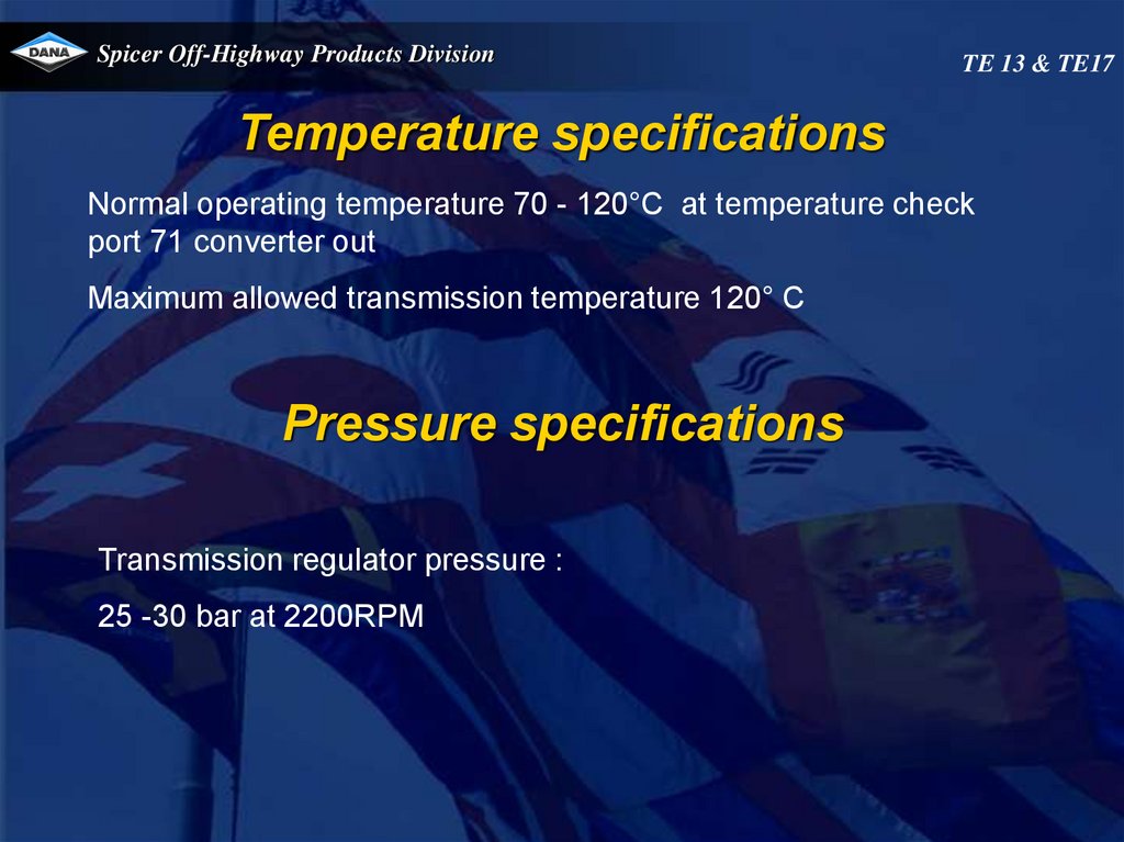
Temperature specifications
Normal operating temperature 70 - 120°C at temperature check
port 71 converter out
Maximum allowed transmission temperature 120° C
Pressure specifications
Transmission regulator pressure :
25 -30 bar at 2200RPM
15.
Spicer Off-HighwayOffOff-Highway Products Division
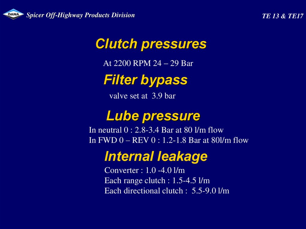
Clutch pressures
At 2200 RPM 24 – 29 Bar
Filter bypass
valve set at 3.9 bar
Lube pressure
In neutral 0 : 2.8-3.4 Bar at 80 l/m flow
In FWD 0 – REV 0 : 1.2-1.8 Bar at 80l/m flow
Internal leakage
Converter : 1.0 -4.0 l/m
Each range clutch : 1.5-4.5 l/m
Each directional clutch : 5.5-9.0 l/m
TE 13 & TE17
16.
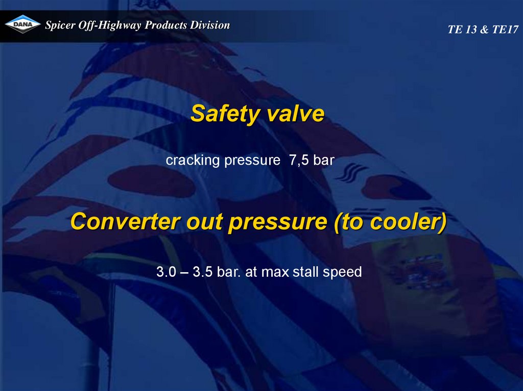
Spicer Off-Highway Products DivisionSafety valve
cracking pressure 7,5 bar
Converter out pressure (to cooler)
3.0 – 3.5 bar. at max stall speed
TE 13 & TE17
17.
Spicer Off-Highway Products DivisionPump flow
At 2200 RPM : 90 to 110 lpm
TE 13 & TE17
18.
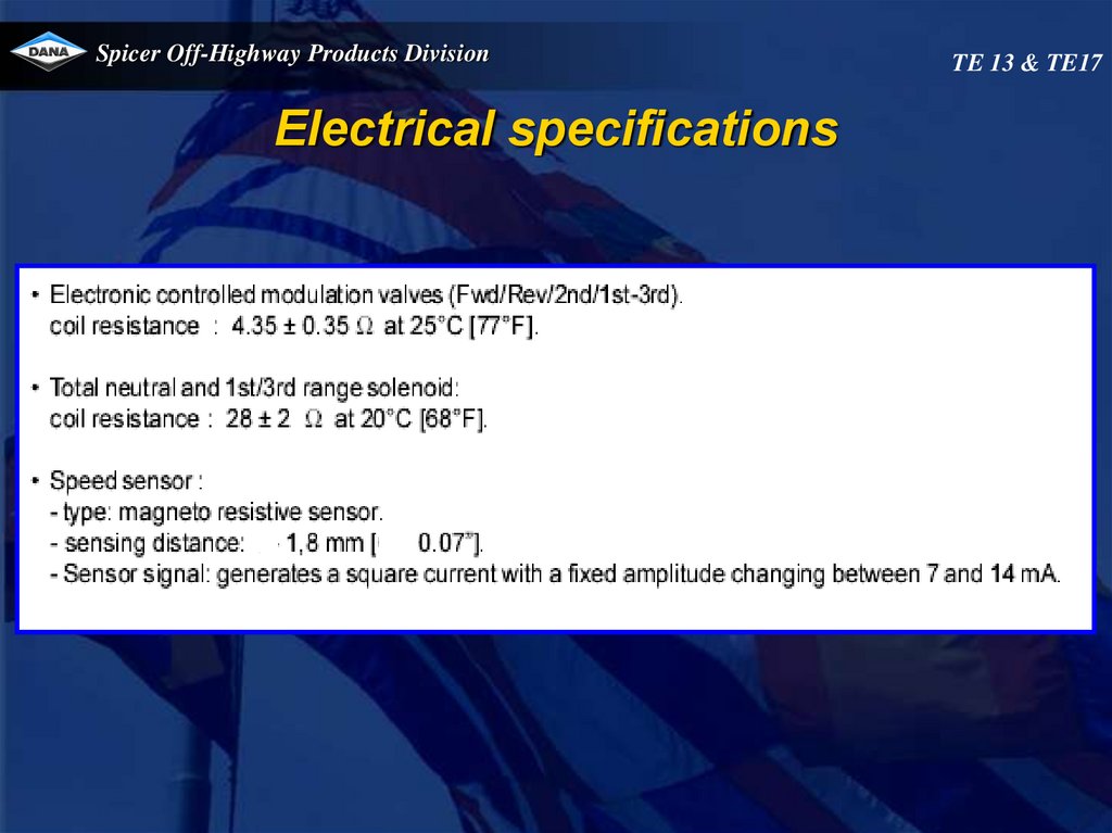
Spicer Off-Highway Products DivisionElectrical specifications
TE 13 & TE17
19.
Spicer Off-Highway Products DivisionTE 13 & TE17
Hydraulic cooler line specifications
HYDRAULIC COOLER LINES SPECIFICATIONS.
Minimum 19 mm internal diameter for lines and fittings.
Suitable for operation from ambient to 120° C continuous operating
temperature.
Must withstand 30 bar continuous pressure and 45 bar intermittent
surges.
Conform SAE J1019 and SAE J517, 100RI.
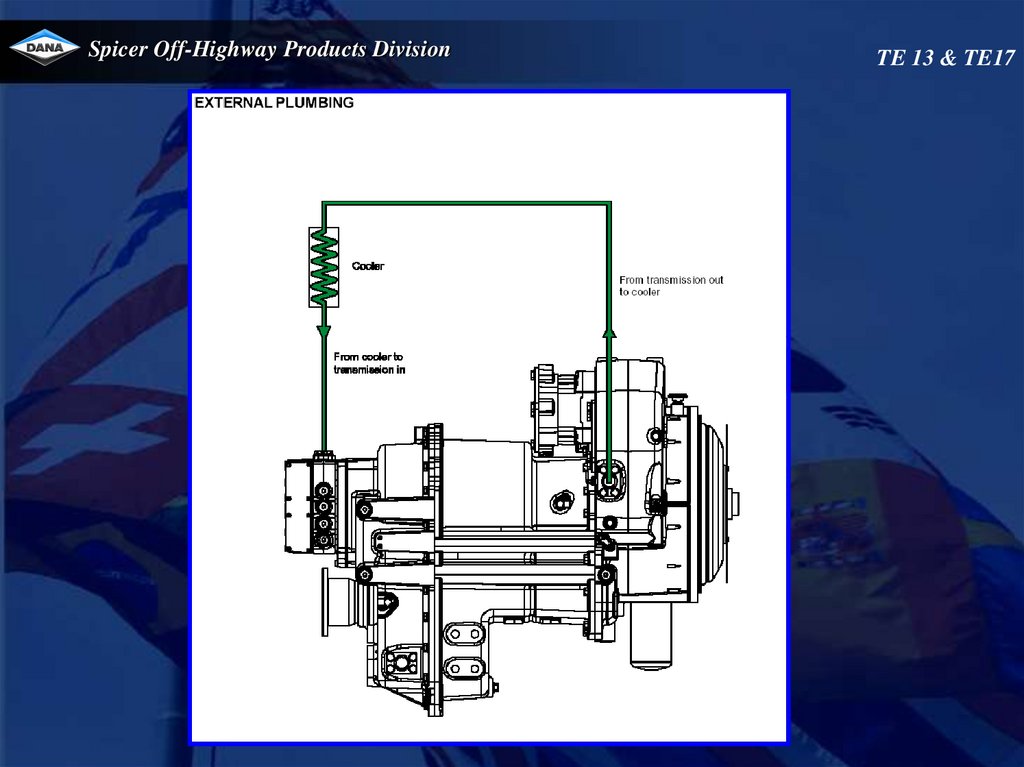
20.
Spicer Off-Highway Products DivisionTE 13 & TE17
21.
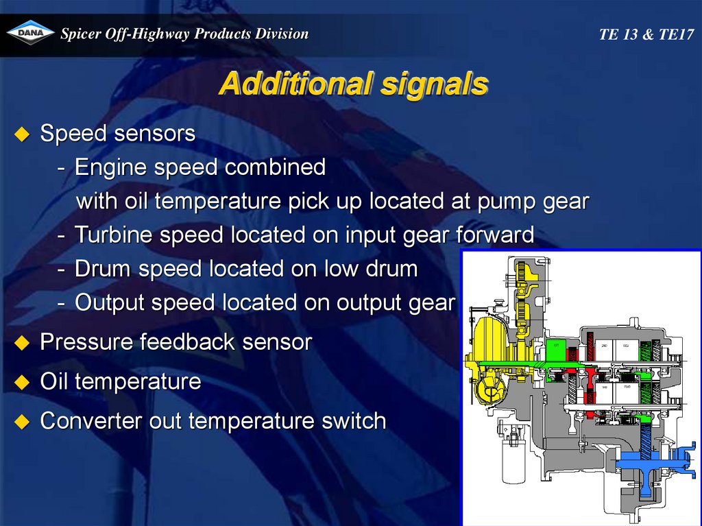
Spicer Off-Highway Products DivisionAdditional signals
Speed sensors
- Engine speed combined
with oil temperature pick up located at pump gear
- Turbine speed located on input gear forward
- Drum speed located on low drum
- Output speed located on output gear
Pressure feedback sensor
Oil temperature
Converter out temperature switch
TE 13 & TE17
22.
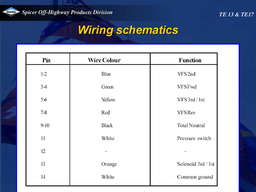
Spicer Off-Highway Products DivisionWiring schematics
Total
neutral
TE 13 & TE17
23.
Spicer Off-Highway Products DivisionWiring schematics
TE 13 & TE17
24.
Spicer Off-Highway Products DivisionControl valve
Variable force solenoids (VFS)
- VFS0 for forward
- VFS1 for 2nd
- VFS2 for reverse
- VFS3 for 1st / 3rd
Pressure reducer
Pressure intensifiers for each VFS
TE 13 & TE17
25.
Spicer Off-Highway Products DivisionTE 13 & TE17
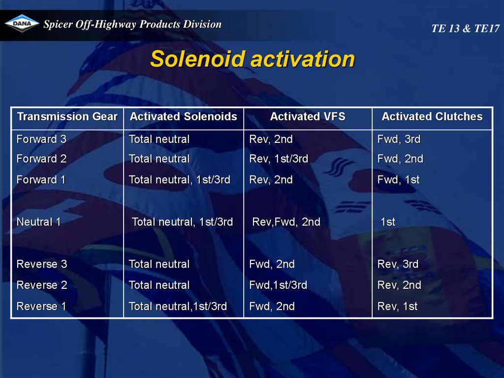
Solenoid activation
Transmission Gear
Activated Solenoids
Activated VFS
Activated Clutches
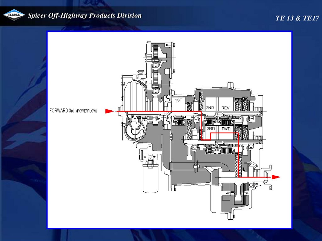
Forward 3
Total neutral
Rev, 2nd
Fwd, 3rd
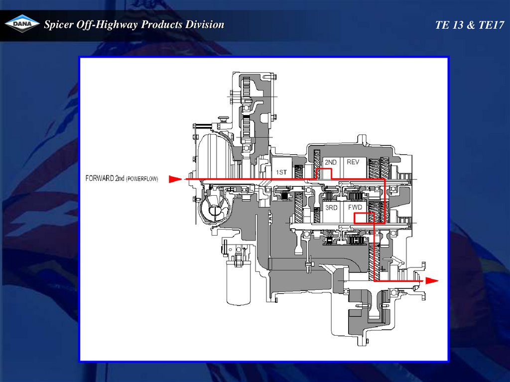
Forward 2
Total neutral
Rev, 1st/3rd
Fwd, 2nd
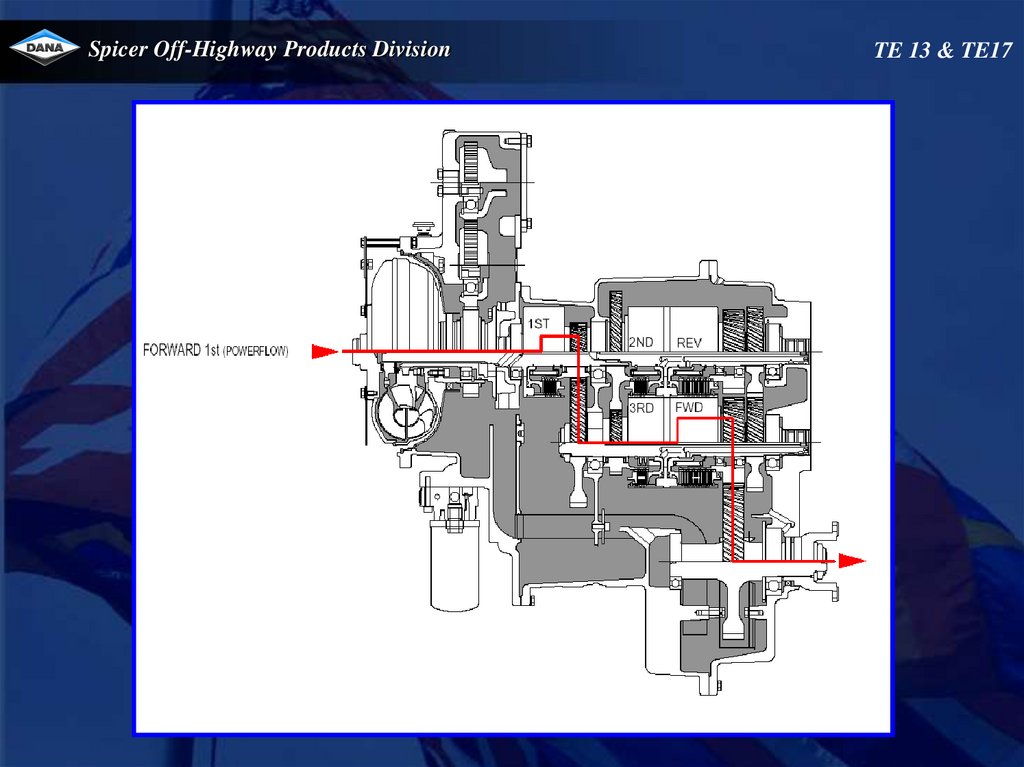
Forward 1
Total neutral, 1st/3rd
Rev, 2nd
Fwd, 1st
Neutral 1
Total neutral, 1st/3rd
Rev,Fwd, 2nd
1st
Reverse 3
Total neutral
Fwd, 2nd
Rev, 3rd
Reverse 2
Total neutral
Fwd,1st/3rd
Rev, 2nd
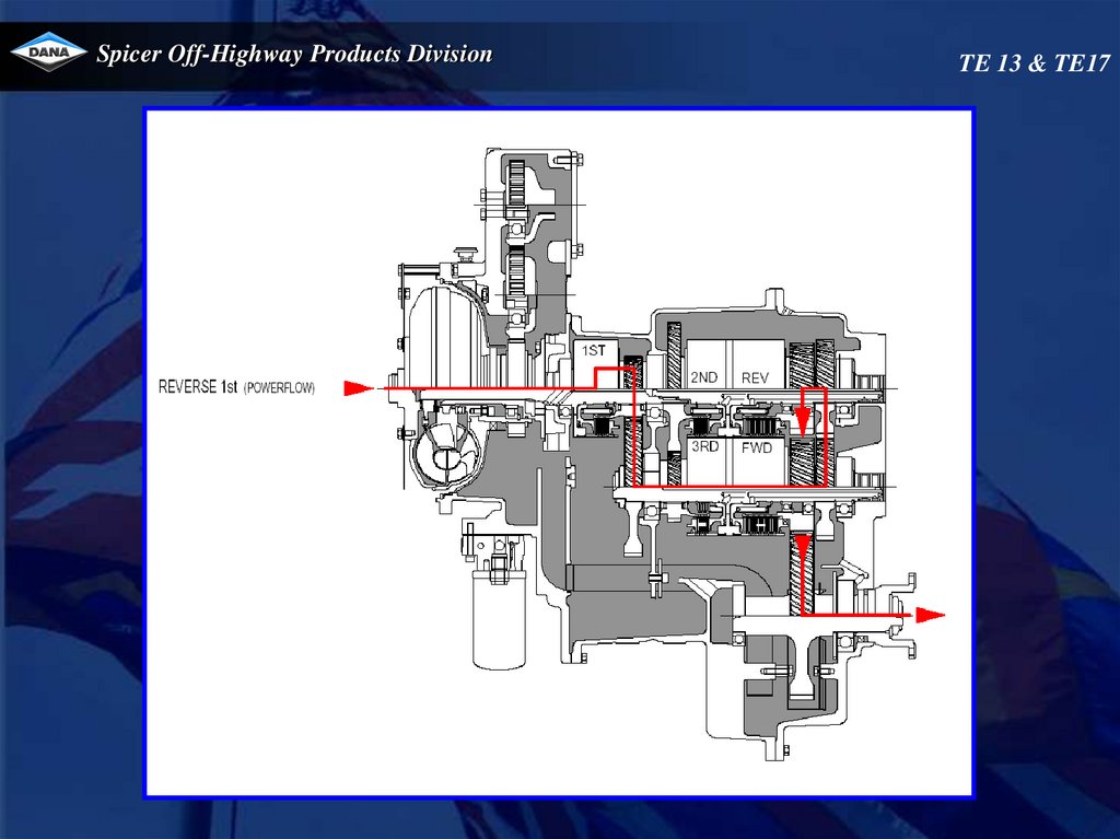
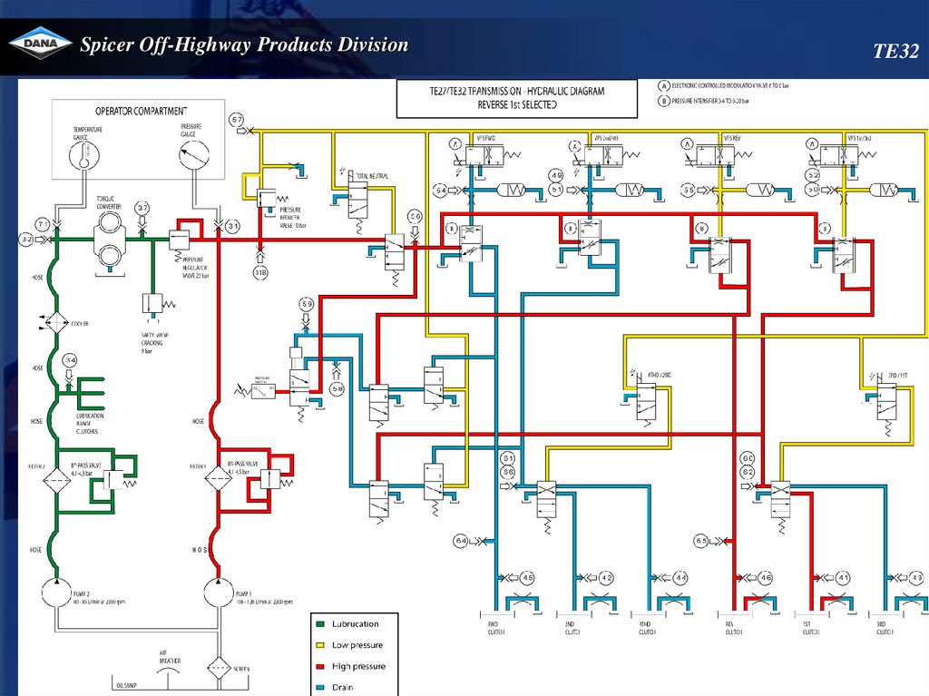
Reverse 1
Total neutral,1st/3rd
Fwd, 2nd
Rev, 1st
26.
Spicer Off-Highway Products DivisionTE13-17
Electronic controlled modulation (E.C.M.)
Oil
pressure
Time
Phase 1
Filling of clutch
Phase 2
Build up of pressure
27.
Spicer Off-Highway Products DivisionTE 13 & TE17
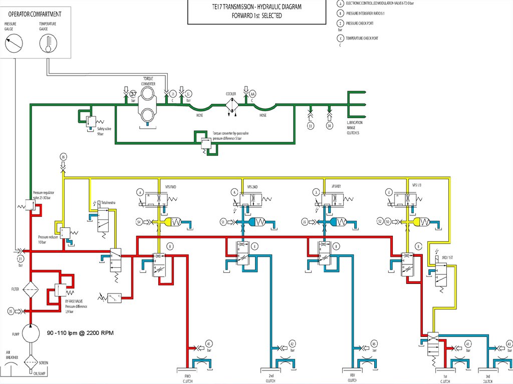
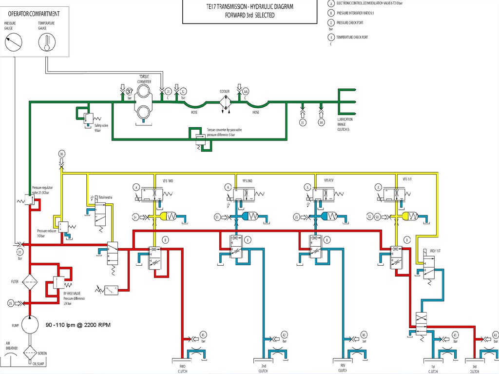
Operation of transmission
The transmission is controlled by an APC200 box. This unit has a
microprocessor that receives certain inputs (gear selector position, speed
sensors,…), which are processed and will give output signals to the control
valve.
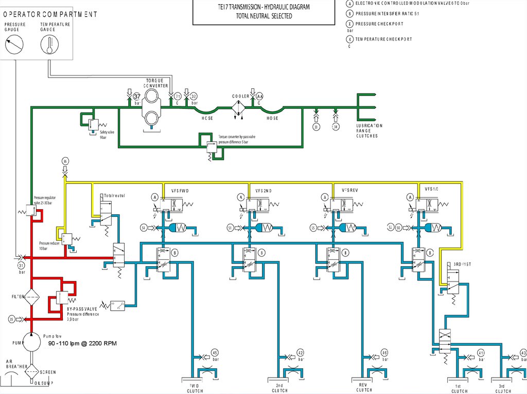
Operation of the valve
Regulated pressure (25-30 bar) is directed to the total neutral shift spool and the
pressure reducer that will decrease the pressure to 10 bar.
This reduced pressure will be used to supply the variable force solenoids(VFS),
total neutral solenoid and 3rd/1st solenoid.
The VFS will give an output pressure curve from 0 to 6 bar proportional to a
current from 1000 mA to 0 mA. The pressure intensifiers with a ratio of 5:1 will
multiply this pressure curve so that a curve from 0 to 30 bar is available for each
directional and range clutch. Between each VFS a pressure intensifier is placed
and an accumulator to dampen any hydraulic vibration.
Directional selection
When a direction (forward or reverse) is selected , total neutral solenoid is
activated and the required directional VFS will provide a pressure rise from 0 to
6 bar. The directional clutch is then fed with modulated pressure supplied
through the pressure intensifier.
28.
Spicer Off-Highway Products DivisionTE 13 & TE17
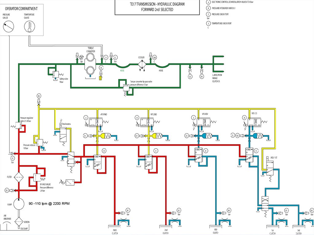
Operation of transmission
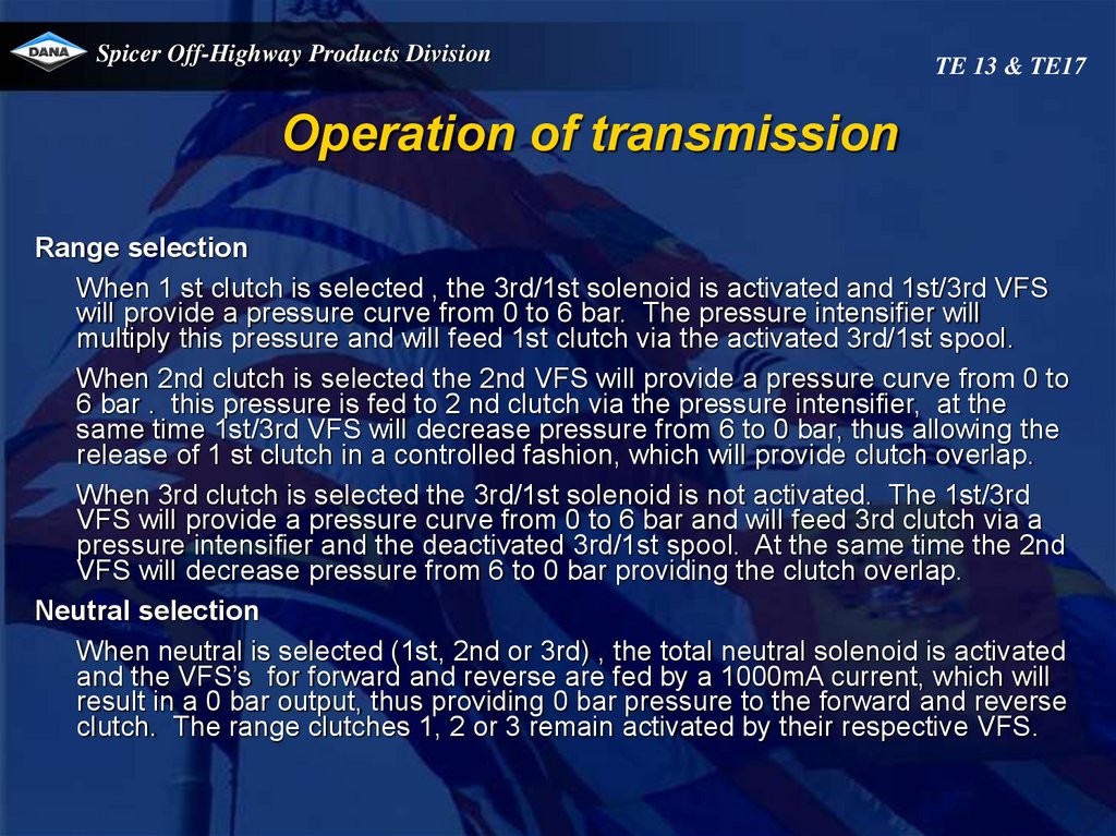
Range selection
When 1 st clutch is selected , the 3rd/1st solenoid is activated and 1st/3rd VFS
will provide a pressure curve from 0 to 6 bar. The pressure intensifier will
multiply this pressure and will feed 1st clutch via the activated 3rd/1st spool.
When 2nd clutch is selected the 2nd VFS will provide a pressure curve from 0 to
6 bar . this pressure is fed to 2 nd clutch via the pressure intensifier, at the
same time 1st/3rd VFS will decrease pressure from 6 to 0 bar, thus allowing the
release of 1 st clutch in a controlled fashion, which will provide clutch overlap.
When 3rd clutch is selected the 3rd/1st solenoid is not activated. The 1st/3rd
VFS will provide a pressure curve from 0 to 6 bar and will feed 3rd clutch via a
pressure intensifier and the deactivated 3rd/1st spool. At the same time the 2nd
VFS will decrease pressure from 6 to 0 bar providing the clutch overlap.
Neutral selection
When neutral is selected (1st, 2nd or 3rd) , the total neutral solenoid is activated
and the VFS’s for forward and reverse are fed by a 1000mA current, which will
result in a 0 bar output, thus providing 0 bar pressure to the forward and reverse
clutch. The range clutches 1, 2 or 3 remain activated by their respective VFS.
29.
Spicer Off-Highway Products DivisionTE 13 & TE17
Operation of transmission
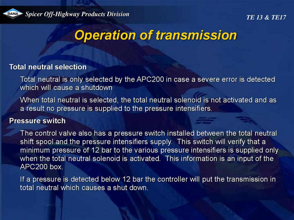
Total neutral selection
Total neutral is only selected by the APC200 in case a severe error is detected
which will cause a shutdown
When total neutral is selected, the total neutral solenoid is not activated and as
a result no pressure is supplied to the pressure intensifiers.
Pressure switch
The control valve also has a pressure switch installed between the total neutral
shift spool and the pressure intensifiers supply. This switch will verify that a
minimum pressure of 12 bar to the various pressure intensifiers is supplied only
when the total neutral solenoid is activated. This information is an input of the
APC200 box.
If a pressure is detected below 12 bar the controller will put the transmission in
total neutral which causes a shut down.
30.
Spicer Off-Highway Products Division37
90 -110 lpm @ 2200 RPM
TE 13 & TE17
31.
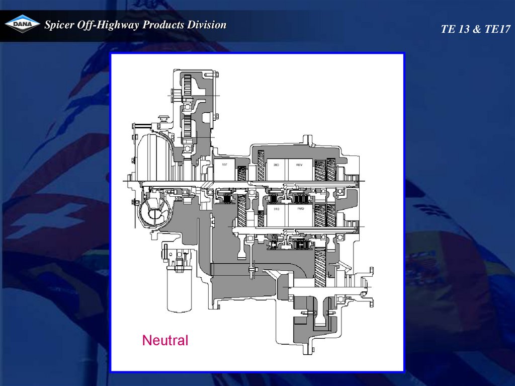
Spicer Off-Highway Products DivisionNeutral
TE 13 & TE17
32.
Spicer Off-Highway Products Division37
90 -110 lpm @ 2200 RPM
TE 13 & TE17
33.
Spicer Off-Highway Products DivisionTE 13 & TE17
34.
Spicer Off-Highway Products Division37
90 -110 lpm @ 2200 RPM
TE 13 & TE17
35.
Spicer Off-Highway Products DivisionTE 13 & TE17
36.
Spicer Off-Highway Products Division37
90 -110 lpm @ 2200 RPM
TE 13 & TE17
37.
Spicer Off-Highway Products DivisionTE 13 & TE17
38.
Spicer Off-Highway Products Division37
90 -110 lpm @ 2200 RPM
TE 13 & TE17
39.
Spicer Off-Highway Products DivisionTE 13 & TE17
40.
Spicer Off-Highway Products DivisionCheck ports
TE 13 & TE17
41.
Spicer Off-Highway Products DivisionTE 13 & TE17
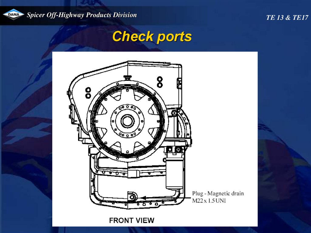
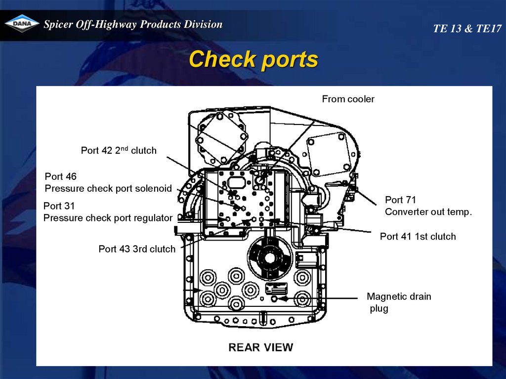
Check ports
From cooler
Port 42 2nd clutch
Port 46
Pressure check port solenoid
Port 31
Pressure check port regulator
Port 71
Converter out temp.
Port 41 1st clutch
Port 43 3rd clutch
Magnetic drain
plug
42.
Spicer Off-Highway Products DivisionTE 13 & TE17
Check ports
To
cooler
Port 37
Safety valve
pressure
Safaty valve
pressure
Safaty valve
mmmpressure
43.
Spicer Off-Highway Products DivisionCheck ports
Engine
Safaty valve
pressure
TE 13 & TE17
44.
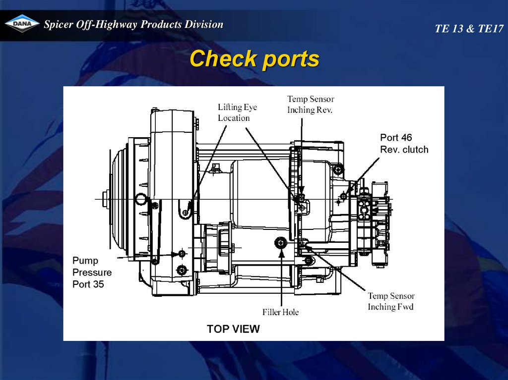
Spicer Off-Highway Products DivisionTE 13 & TE17
Check ports
Port 46
Rev. clutch
Rev.
clutch
Pump
Pressure
Port 35
45.
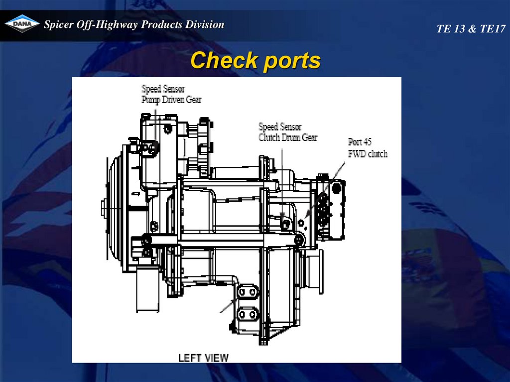
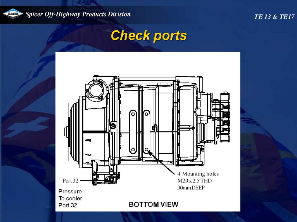
Spicer Off-Highway Products DivisionCheck ports
Pressure
To cooler
Port 32
TE 13 & TE17
46.
Spicer Off-Highway Products DivisionTE 13 & TE17
Check ports Control valve
VFS REV
Port 55
VFS 2nd
Port 51
VFS FWD
Port 54
VFS 1st/3rd
Port 50/52
47.
Spicer Off-Highway Products DivisionTE 13 & TE17
Control valve installation instruction
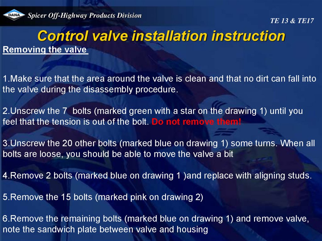
Removing the valve
1.Make sure that the area around the valve is clean and that no dirt can fall into
the valve during the disassembly procedure.
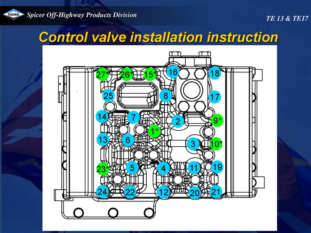
2.Unscrew the 7 bolts (marked green with a star on the drawing 1) until you
feel that the tension is out of the bolt. Do not remove them!
3.Unscrew the 20 other bolts (marked blue on drawing 1) some turns. When all
bolts are loose, you should be able to move the valve a bit
4.Remove 2 bolts (marked blue on drawing 1 )and replace with aligning studs.
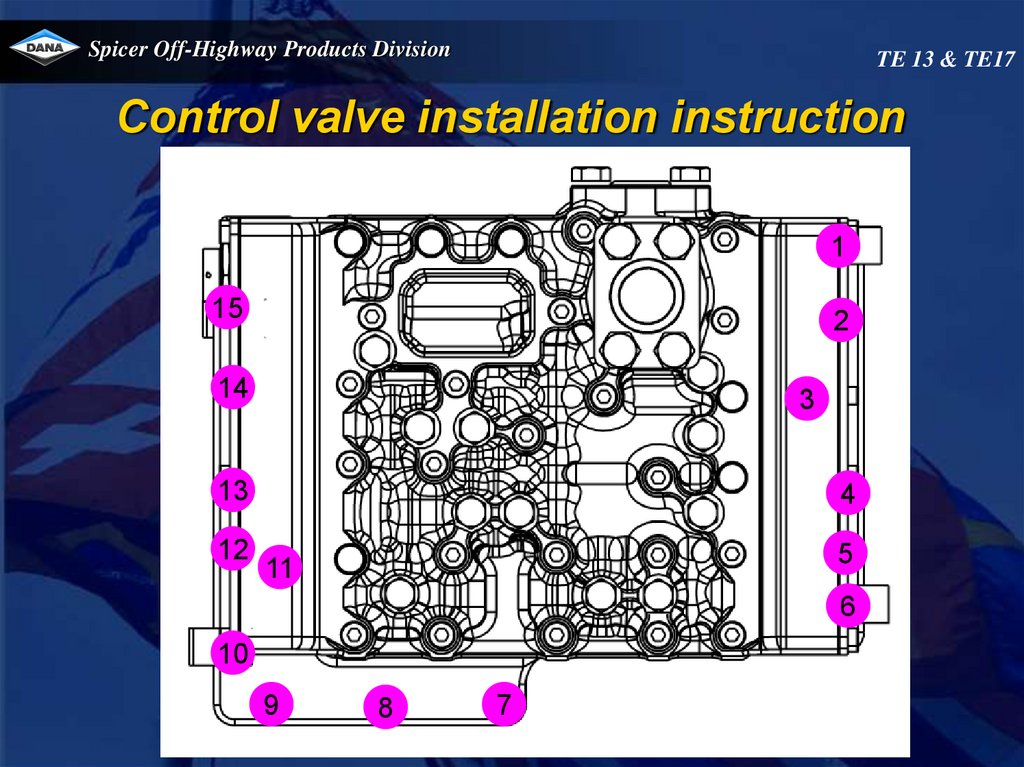
5.Remove the 15 bolts (marked pink on drawing 2)
6.Remove the remaining bolts (marked blue on drawing 1) and remove valve,
note the sandwich plate between valve and housing
48.
Spicer Off-Highway Products DivisionTE 13 & TE17
Control valve installation instruction
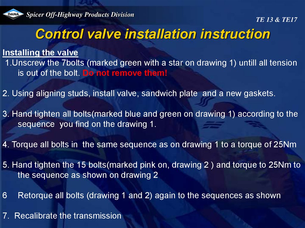
Installing the valve
1.Unscrew the 7bolts (marked green with a star on drawing 1) untill all tension
is out of the bolt. Do not remove them!
2. Using aligning studs, install valve, sandwich plate and a new gaskets.
3. Hand tighten all bolts(marked blue and green on drawing 1) according to the
sequence you find on the drawing 1.
4. Torque all bolts in the same sequence as on drawing 1 to a torque of 25Nm
5. Hand tighten the 15 bolts(marked pink on, drawing 2 ) and torque to 25Nm to
the sequence as shown on drawing 2
6
Retorque all bolts (drawing 1 and 2) again to the sequences as shown
7. Recalibrate the transmission
49.
Spicer Off-Highway Products DivisionTE 13 & TE17
Control valve installation instruction
27*
26*
16
15*
25
18
8
14
7
17
9*
2
1*
13
6
3
10*
23*
5
4
11
19
24
22
12
20
21
50.
Spicer Off-Highway Products DivisionTE 13 & TE17
Control valve installation instruction
1
15
2
14
3
13
12
4
5
11
6
10
9
8
7
51.
Spicer Off-Highway Products DivisionTE 13 & TE17
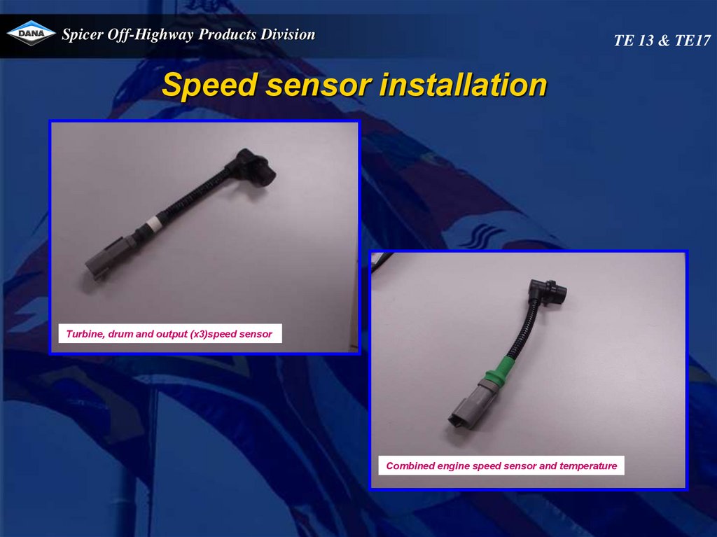
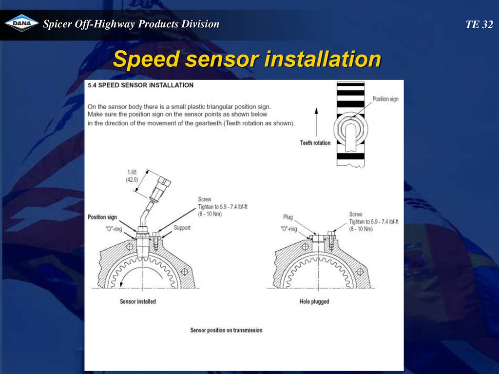
Speed sensor installation
Turbine, drum and output (x3)speed sensor
Combined engine speed sensor and temperature
52.
Spicer Off-Highway Products DivisionSpeed sensor installation
TE 13 & TE17
53.
Spicer Off-Highway Products DivisionSpeed sensor installation
TE 13 & TE17
54.
Spicer Off-Highway Products DivisionSpeed sensor installation
TE 13 & TE17
55. TE32 transmission
Spicer Off-Highway Products DivisionTE32 transmission
56.
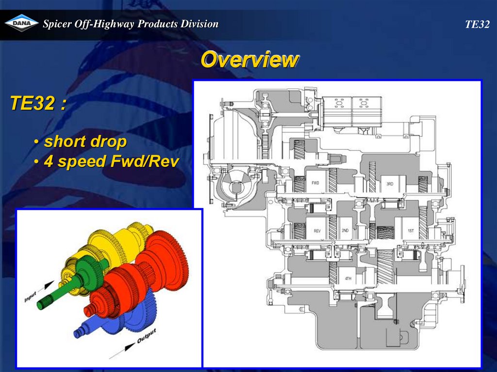
Spicer Off-Highway Products DivisionOverview
TE32 :
• short drop
• 4 speed Fwd/Rev
TE32
57.
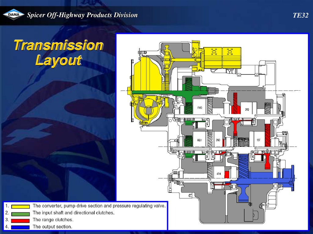
Spicer Off-Highway Products DivisionTransmission
Layout
TE32
58.
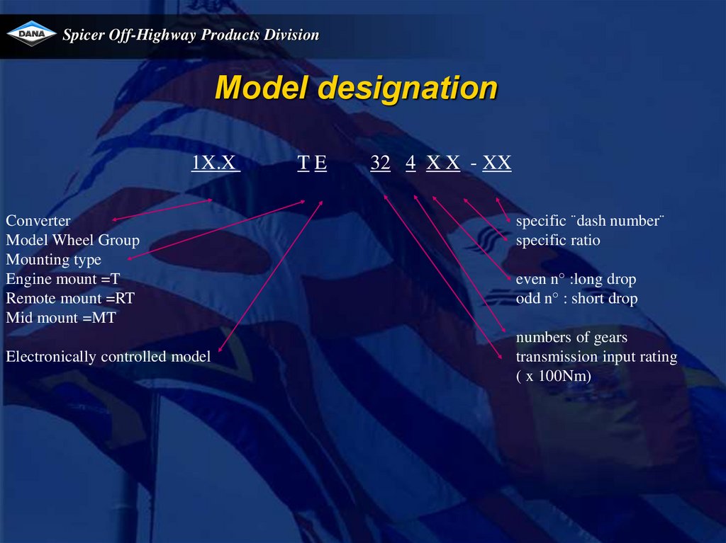
Spicer Off-Highway Products DivisionModel designation
1X.X
Converter
Model Wheel Group
Mounting type
Engine mount =T
Remote mount =RT
Mid mount =MT
Electronically controlled model
TE
32 4 X X - XX
specific ¨dash number¨
specific ratio
even n° :long drop
odd n° : short drop
numbers of gears
transmission input rating
( x 100Nm)
59.
Spicer Off-Highway Products DivisionTE32
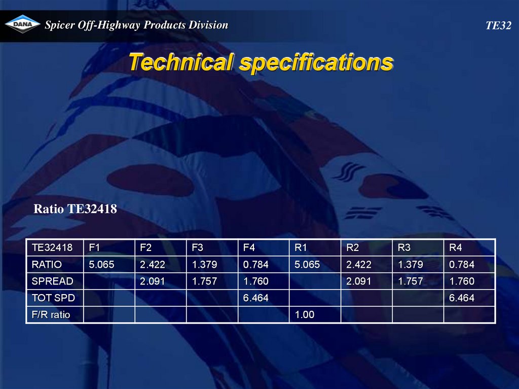
Technical specifications
Ratio TE32418
TE32418
F1
F2
F3
F4
R1
R2
R3
R4
RATIO
5.065
2.422
1.379
0.784
5.065
2.422
1.379
0.784
2.091
1.757
1.760
2.091
1.757
1.760
SPREAD
TOT SPD
F/R ratio
6.464
6.464
1.00
60.
Spicer Off-Highway Products DivisionTechnical specifications
Output flange rotation – (transmission forward clutch engaged)
Model
Short Drop
Long Drop
Output
Opposite
Same
Drop :
- Long Drop
- Short Drop
624.6mm
317.8mm
TE32
61.
Spicer Off-Highway Products DivisionTechnical specifications
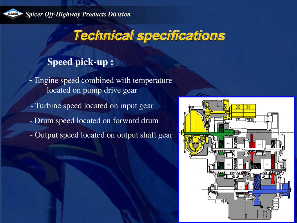
Speed pick-up :
- Engine speed combined with temperature
located on pump drive gear
- Turbine speed located on input gear
- Drum speed located on forward drum
- Output speed located on output shaft gear
62.
Spicer Off-Highway Products DivisionTechnical specifications
Converter/Transmission Oil System
Capacity (Approximate: measured at 600 RPM input speed and oil temp between 60 and 70°C,
neutral) Short drop 60L Long drop 75L Lines and cooler not included
Oil Type
ONLY ATF Dexron III approved
viscosity at 40°C: 33 38 cSt
viscosity at 100°C: 7 8 cSt
flash point: min 160°C
pour point: max –42°C
Oil change
1000 hours
Filtration
2 x Spin On
change every 1000 hours
first change: 100 hrs or after rebuild
TE32
63.
Spicer Off-Highway Products DivisionTE32
Temperature specifications
Normal operating temperature 70 - 120°C at temperature check port converter
out
Maximum allowed transmission temperature 120° C
Pressure specifications
Transmission regulator pressure :
• 600 RPM 22.5-24.5 bar
• 2200 RPM 23.5-25.5 bar
64.
Spicer Off-Highway Products DivisionClutch pressures
At 1800 RPM 20.5 - 24.5 bar
Filter bypass
valve set at 4.1 to 4.5 bar
Lube pressure
0.9 – 1.4 bar at 100 l/min. lube flow.(+/-1000RPM)
Internal leakage @ 1800 RPM
Fwd/Rev max 4 l/min
1st max 9.2 l/min
2nd/3rd/4th max 4 l/min
TE32
65.
Spicer Off-Highway Products DivisionSavety valve
cracking pressure 8.8-9.6 bar
Converter out pressure (to cooler)
5 bar min. at 2000 RPM and max. 8.5
bar at no load governed speed.
Pump flow
System pump flow : 108-128 l/min at 2200
RPM.
Lube pump flow : 80-95 l/min at 2200 RPM.
TE32
66.
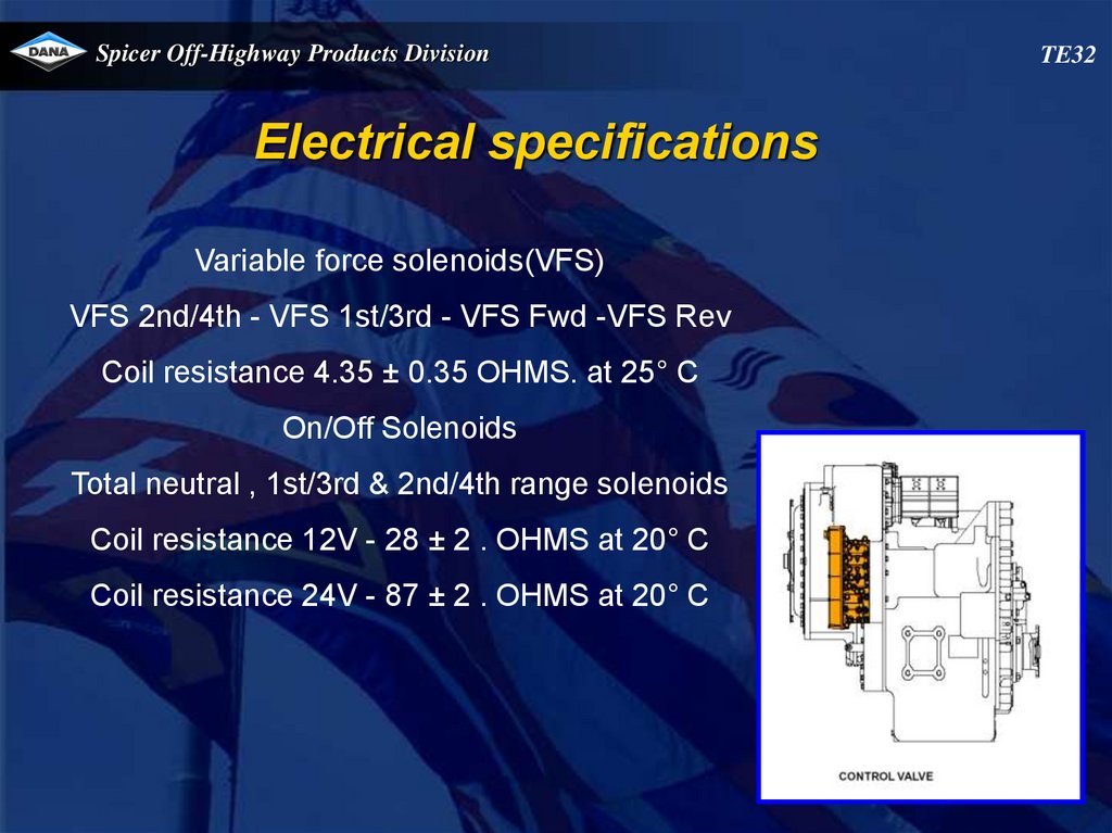
Spicer Off-Highway Products DivisionElectrical specifications
Variable force solenoids(VFS)
VFS 2nd/4th - VFS 1st/3rd - VFS Fwd -VFS Rev
Coil resistance 4.35 ± 0.35 OHMS. at 25° C
On/Off Solenoids
Total neutral , 1st/3rd & 2nd/4th range solenoids
Coil resistance 12V - 28 ± 2 . OHMS at 20° C
Coil resistance 24V - 87 ± 2 . OHMS at 20° C
TE32
67.
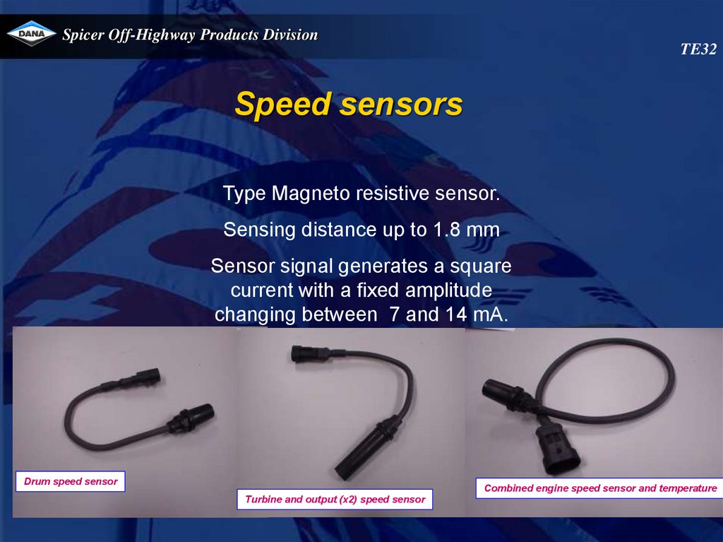
Spicer Off-Highway Products DivisionTE32
Speed sensors
Type Magneto resistive sensor.
Sensing distance up to 1.8 mm
Sensor signal generates a square
current with a fixed amplitude
changing between 7 and 14 mA.
Drum speed sensor
Combined engine speed sensor and temperature
Turbine and output (x2) speed sensor
68.
Spicer Off-Highway Products DivisionHydraulic cooler line specifications
HYDRAULIC COOLER LINES SPECIFICATIONS.
Minimum 32 mm internal diameter for lines and fittings.
Suitable for operation from ambient to 120° C continuous operating
temperature.
Must withstand 30 bar continuous pressure and 45 bar intermittent
surges.
Conform SAE J1019 and SAE J517, 100RI.
TE32
69.
Spicer Off-Highway Products DivisionTE32
70.
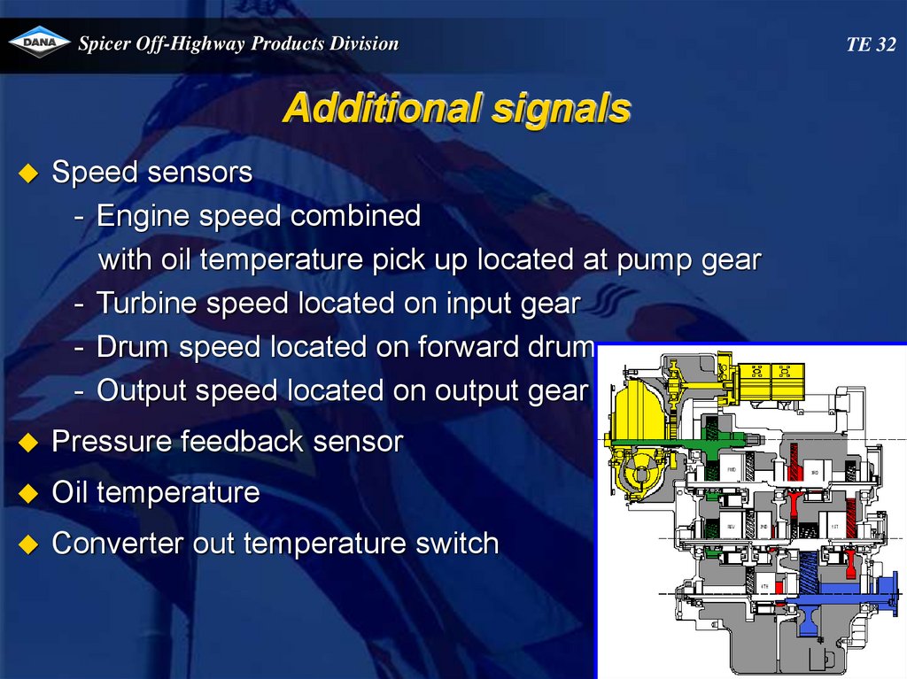
Spicer Off-Highway Products DivisionAdditional signals
Speed sensors
- Engine speed combined
with oil temperature pick up located at pump gear
- Turbine speed located on input gear
- Drum speed located on forward drum
- Output speed located on output gear
Pressure feedback sensor
Oil temperature
Converter out temperature switch
TE 32
71.
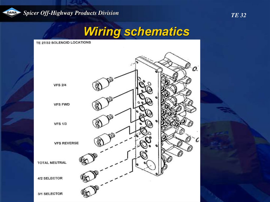
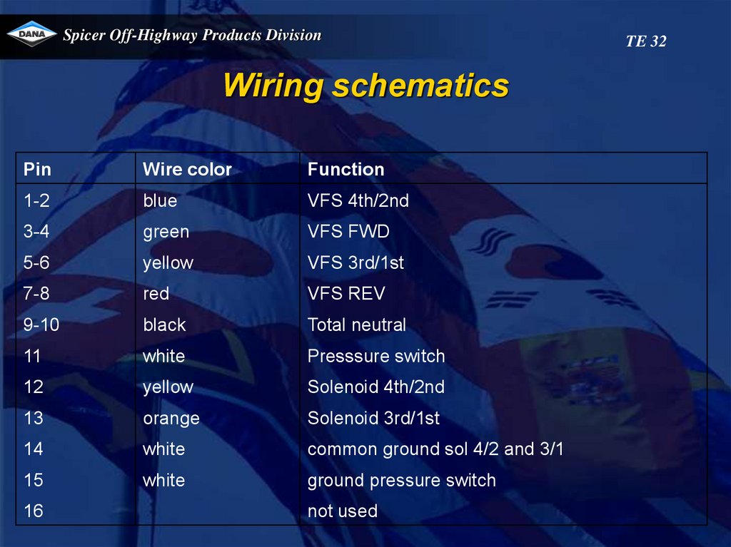
Spicer Off-Highway Products DivisionWiring schematics
TE 32
72.
Spicer Off-Highway Products DivisionWiring schematics
Pin
Wire color
Function
1-2
blue
VFS 4th/2nd
3-4
green
VFS FWD
5-6
yellow
VFS 3rd/1st
7-8
red
VFS REV
9-10
black
Total neutral
11
white
Presssure switch
12
yellow
Solenoid 4th/2nd
13
orange
Solenoid 3rd/1st
14
white
common ground sol 4/2 and 3/1
15
white
ground pressure switch
16
not used
TE 32
73.
Spicer Off-Highway Products DivisionTE32
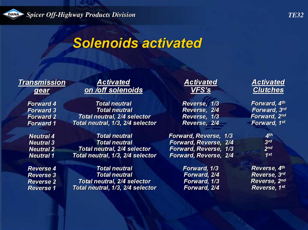
Solenoids activated
Transmission
gear
Activated
on /off solenoids
Forward 4
Forward 3
Forward 2
Forward 1
Total neutral
Total neutral
Total neutral, 2/4 selector
Total neutral, 1/3, 2/4 selector
Reverse,
Reverse,
Reverse,
Reverse,
Neutral 4
Neutral 3
Neutral 2
Neutral 1
Total neutral
Total neutral
Total neutral, 2/4 selector
Total neutral, 1/3, 2/4 selector
Forward, Reverse,
Forward, Reverse,
Forward, Reverse,
Forward, Reverse,
Reverse 4
Reverse 3
Reverse 2
Reverse 1
Total neutral
Total neutral
Total neutral, 2/4 selector
Total neutral, 1/3, 2/4 selector
Activated
Clutches
Activated
VFS’s
Forward, 4th
Forward, 3rd
Forward, 2nd
Forward, 1st
1/3
2/4
1/3
2/4
Forward, 1/3
Forward, 2/4
Forward, 1/3
Forward, 2/4
1/3
2/4
1/3
2/4
4th
3rd
2nd
1st
Reverse, 4th
Reverse, 3rd
Reverse, 2nd
Reverse, 1st
74.
Spicer Off-Highway Products DivisionTE27-32
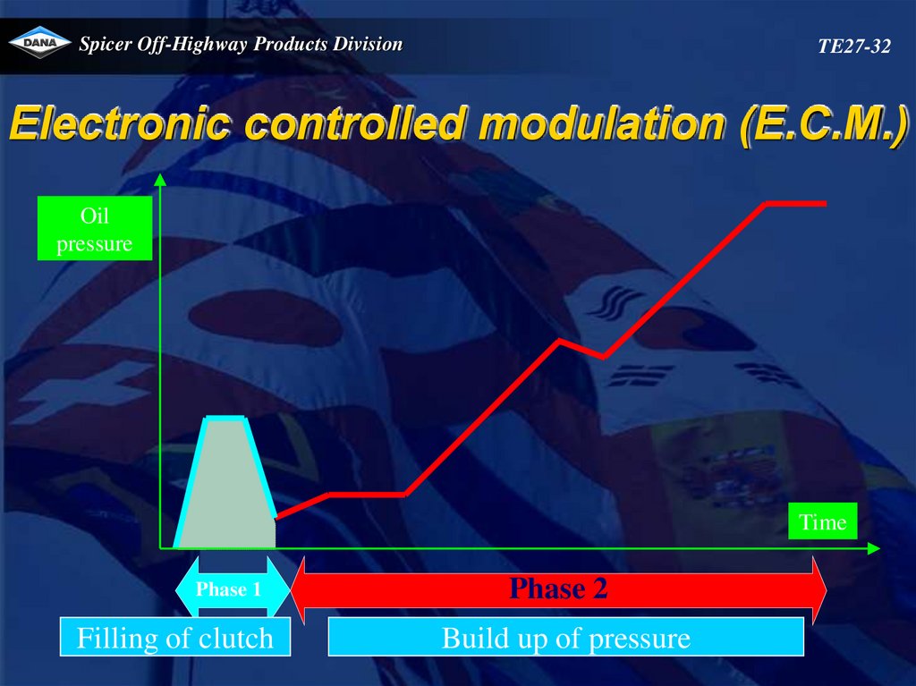
Electronic controlled modulation (E.C.M.)
Oil
pressure
Time
Phase 1
Filling of clutch
Phase 2
Build up of pressure
75.
Spicer Off-Highway Products DivisionTE32
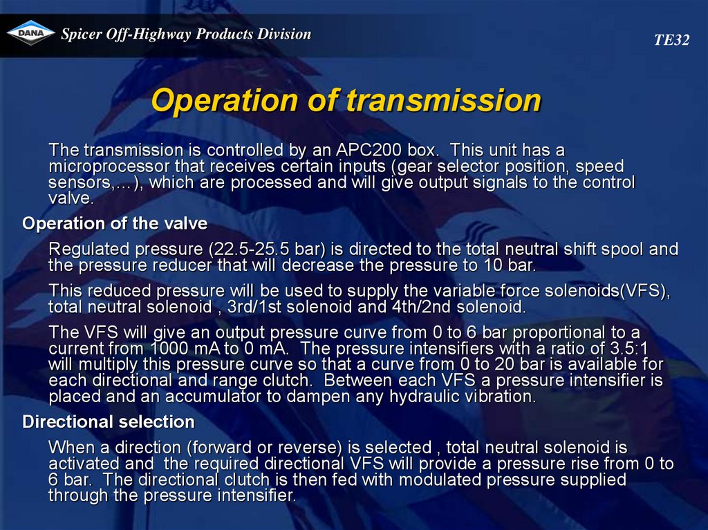
Operation of transmission
The transmission is controlled by an APC200 box. This unit has a
microprocessor that receives certain inputs (gear selector position, speed
sensors,…), which are processed and will give output signals to the control
valve.
Operation of the valve
Regulated pressure (22.5-25.5 bar) is directed to the total neutral shift spool and
the pressure reducer that will decrease the pressure to 10 bar.
This reduced pressure will be used to supply the variable force solenoids(VFS),
total neutral solenoid , 3rd/1st solenoid and 4th/2nd solenoid.
The VFS will give an output pressure curve from 0 to 6 bar proportional to a
current from 1000 mA to 0 mA. The pressure intensifiers with a ratio of 3.5:1
will multiply this pressure curve so that a curve from 0 to 20 bar is available for
each directional and range clutch. Between each VFS a pressure intensifier is
placed and an accumulator to dampen any hydraulic vibration.
Directional selection
When a direction (forward or reverse) is selected , total neutral solenoid is
activated and the required directional VFS will provide a pressure rise from 0 to
6 bar. The directional clutch is then fed with modulated pressure supplied
through the pressure intensifier.
76.
Spicer Off-Highway Products DivisionTE32
Operation of transmission
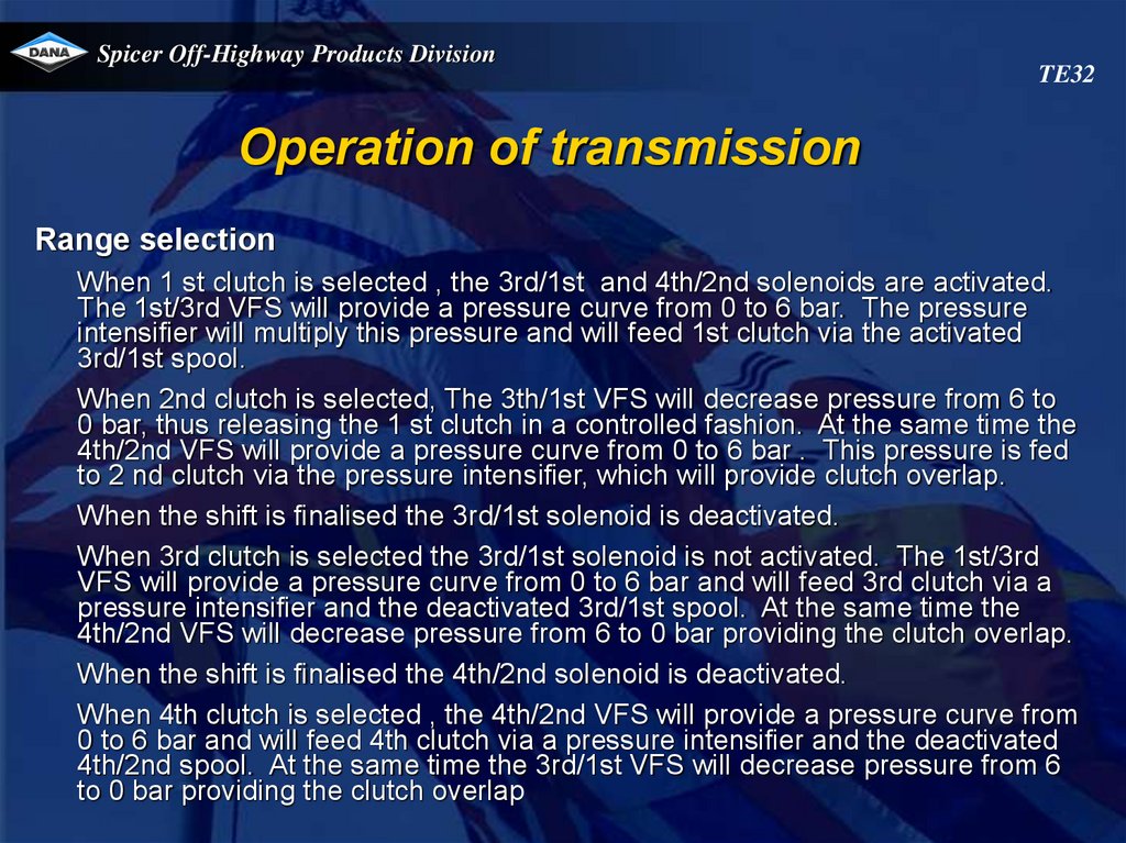
Range selection
When 1 st clutch is selected , the 3rd/1st and 4th/2nd solenoids are activated.
The 1st/3rd VFS will provide a pressure curve from 0 to 6 bar. The pressure
intensifier will multiply this pressure and will feed 1st clutch via the activated
3rd/1st spool.
When 2nd clutch is selected, The 3th/1st VFS will decrease pressure from 6 to
0 bar, thus releasing the 1 st clutch in a controlled fashion. At the same time the
4th/2nd VFS will provide a pressure curve from 0 to 6 bar . This pressure is fed
to 2 nd clutch via the pressure intensifier, which will provide clutch overlap.
When the shift is finalised the 3rd/1st solenoid is deactivated.
When 3rd clutch is selected the 3rd/1st solenoid is not activated. The 1st/3rd
VFS will provide a pressure curve from 0 to 6 bar and will feed 3rd clutch via a
pressure intensifier and the deactivated 3rd/1st spool. At the same time the
4th/2nd VFS will decrease pressure from 6 to 0 bar providing the clutch overlap.
When the shift is finalised the 4th/2nd solenoid is deactivated.
When 4th clutch is selected , the 4th/2nd VFS will provide a pressure curve from
0 to 6 bar and will feed 4th clutch via a pressure intensifier and the deactivated
4th/2nd spool. At the same time the 3rd/1st VFS will decrease pressure from 6
to 0 bar providing the clutch overlap
77.
Spicer Off-Highway Products DivisionTE32
Operation of transmission
Neutral selection
When neutral is selected (1st, 2nd, 3rd or 4th) , the total neutral solenoid
is activated and the VFS’s for forward and reverse are fed by a 1000mA
current, which will result in a 0 bar output, thus providing 0 bar pressure
to the forward and reverse clutch. The range clutches 1, 2,3 or 4
remain activated by their respective VFS.
Total neutral selection
Total neutral is only selected by the APC200 in case a severe error is
detected which will cause a shutdown
When total neutral is selected, the total neutral solenoid is not activated
and as a result no pressure is supplied to the pressure intensifiers.
78.
Spicer Off-Highway Products DivisionTE32
Operation of transmission
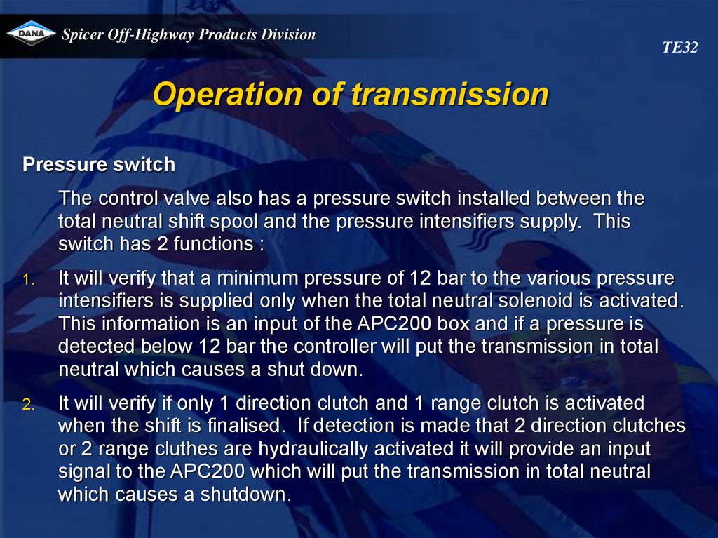
Pressure switch
The control valve also has a pressure switch installed between the
total neutral shift spool and the pressure intensifiers supply. This
switch has 2 functions :
1.
It will verify that a minimum pressure of 12 bar to the various pressure
intensifiers is supplied only when the total neutral solenoid is activated.
This information is an input of the APC200 box and if a pressure is
detected below 12 bar the controller will put the transmission in total
neutral which causes a shut down.
2.
It will verify if only 1 direction clutch and 1 range clutch is activated
when the shift is finalised. If detection is made that 2 direction clutches
or 2 range cluthes are hydraulically activated it will provide an input
signal to the APC200 which will put the transmission in total neutral
which causes a shutdown.
79.
Spicer Off-Highway Products DivisionTE32
VFS 2/4
VFS 1/3
80.
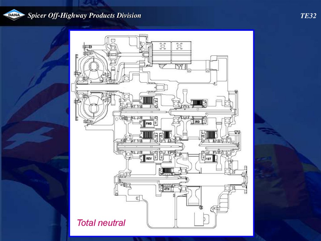
Spicer Off-Highway Products DivisionTotal neutral
TE32
81.
Spicer Off-Highway Products DivisionTE32
VFS 2/4
VFS 1/3
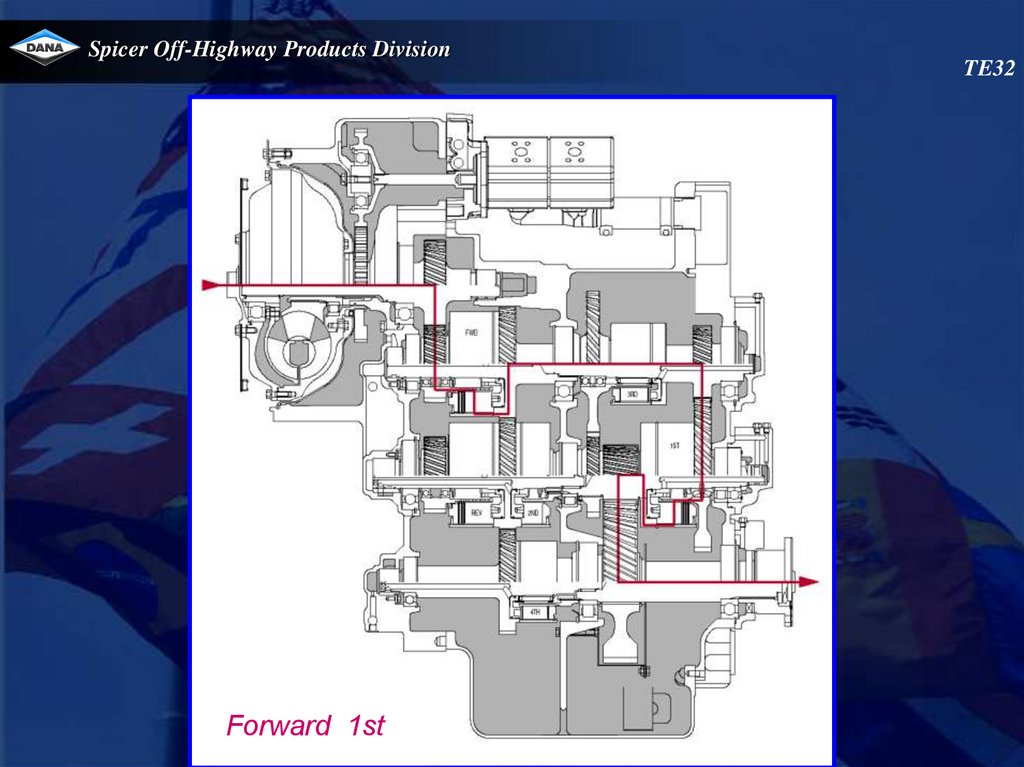
82.
Spicer Off-Highway Products DivisionForward 1st
TE32
83.
Spicer Off-Highway Products DivisionTE32
VFS 2/4
VFS 1/3
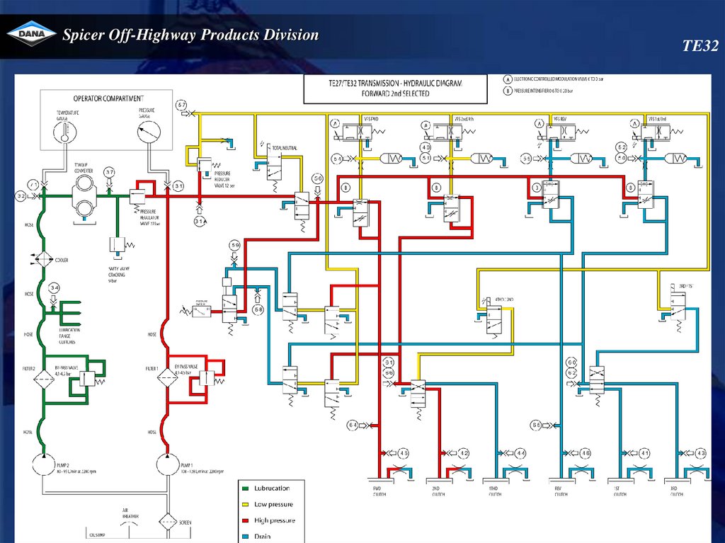
84.
Spicer Off-Highway Products DivisionForward 2nd
TE32
85.
Spicer Off-Highway Products DivisionTE32
VFS 2/4
VFS 1/3
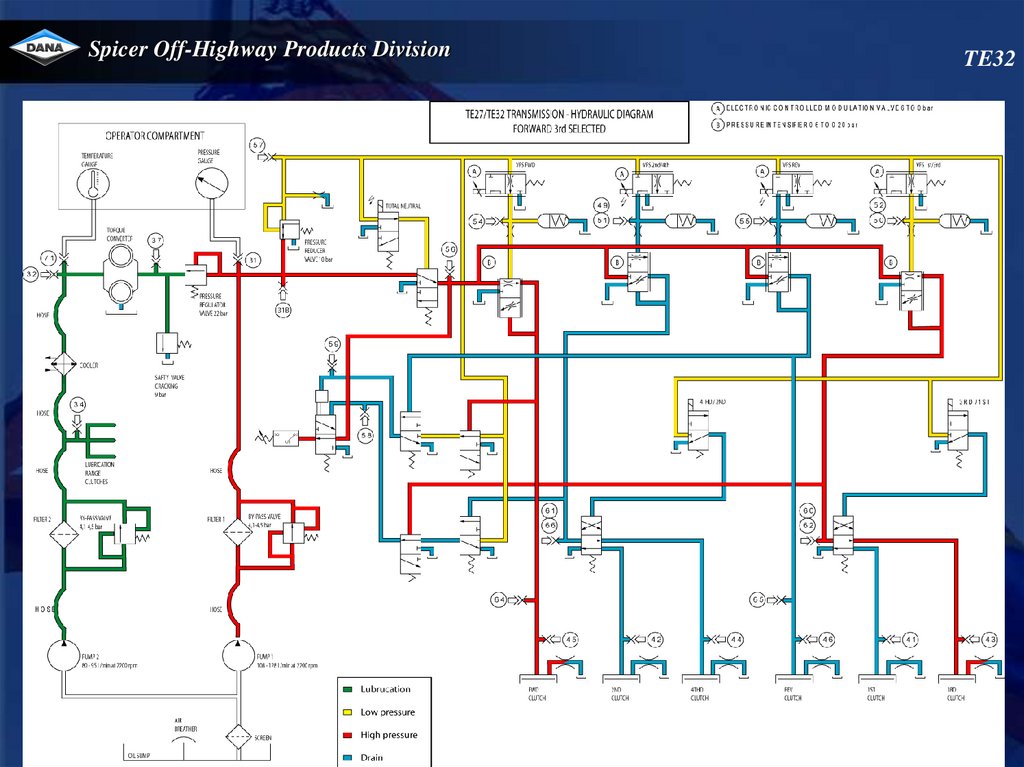
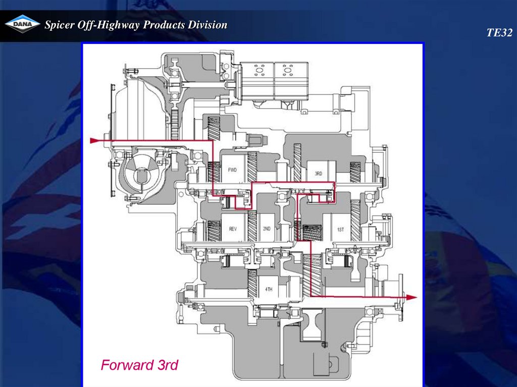
86.
Spicer Off-Highway Products DivisionForward 3rd
TE32
87.
Spicer Off-Highway Products DivisionTE32
VFS 2/4
VFS 1/3
88.
Spicer Off-Highway Products DivisionForward 4th
TE32
89.
Spicer Off-Highway Products DivisionTE32
VFS 2/4
VFS 1/3
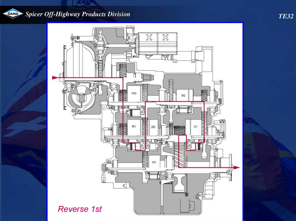
90.
Spicer Off-Highway Products DivisionReverse 1st
TE32
91.
Spicer Off-Highway Products DivisionTE32
Connections - top view
To remote filter from pump 2
Oil fill
¾
npft
To remote filter from pump 1
92.
Spicer Off-Highway Products DivisionTE32
Checkports - left view
Pressure check 1st clutch port 41
Oil level check port
1/4 NPT
93.
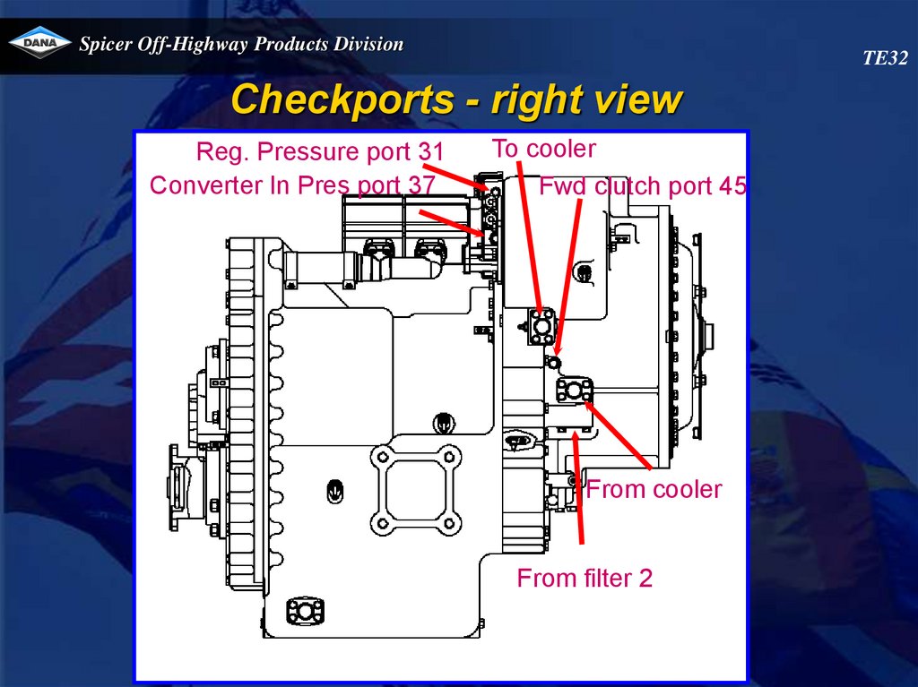
Spicer Off-Highway Products DivisionTE32
Checkports - right view
Reg. Pressure port 31
Converter In Pres port 37
To cooler
Fwd clutch port 45
From cooler
From filter 2
94.
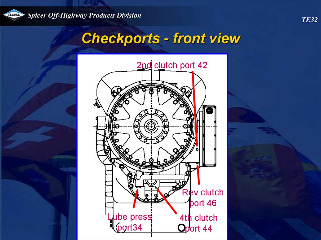
Spicer Off-Highway Products DivisionTE32
Checkports - front view
2nd clutch port 42
Rev clutch
port 46
Lube press
port34
4th clutch
port 44
95.
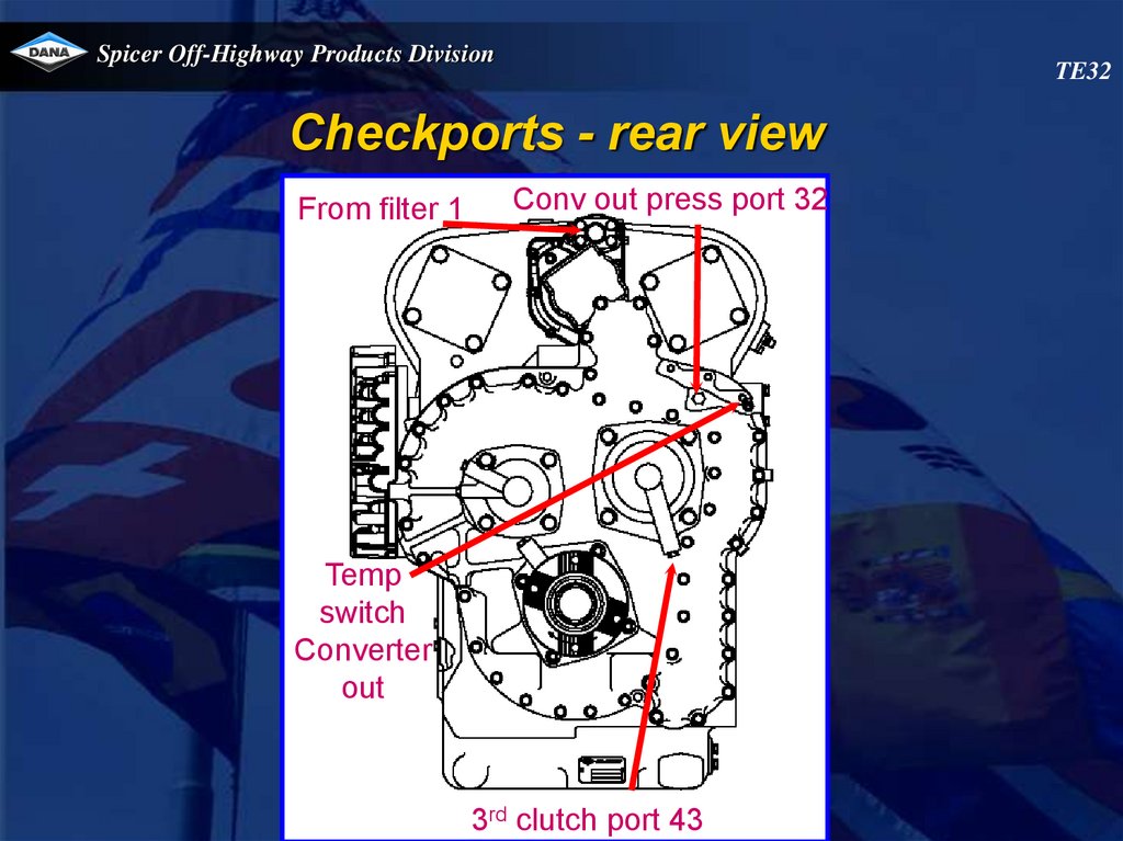
Spicer Off-Highway Products DivisionTE32
Checkports - rear view
From filter 1
Conv out press port 32
Temp
switch
Converter
out
3rd clutch port 43
96.
Spicer Off-Highway Products DivisionTE32
Speed sensor location
Engine speed & transmission temperature
sensor
Drum speed sensor
Turbine speed sensor
Output speed sensor
97.
Spicer Off-Highway Products DivisionTE32
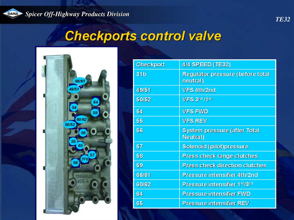
Checkports control valve
Checkport
4/4 SPEED (TE32)
31b
Regulator pressure (before total
neutral)
49/51
VFS 4th/2nd
FF
64
50/52
VFS 3rd /1st
N
59
54
VFS FWD
55
VFS REV
56
System pressure (after Total
Neutral)
57
Solenoid (pilot)pressure
58
Press check range clutches
59
Press check direction clutches
66/61
Pressure intensifier 4th/2nd
60/62
Pressure intensifier 1st/3rd
64
Pressure intensifier FWD
65
Pressure intensifier REV
66/61
G
A
49/51
54
B
60/62
H
50/52
C
56
K
55
D
65
E
58
M
31b
J
57
L
98.
Spicer Off-Highway Products DivisionTE32
Control valve replacement
Removing the valve
1.Make sure that the area around the valve is clean and that no dirt can fall into the valve during the
disassembly procedure.
2.Unscrew the 4 hex bolts (marked pink on drawing) until you feel that the tension is out of the bolt.
Do not remove them!
3.Unscrew the 15 other bolts (marked blue) some turns. When all bolts are loose, you should be able to
move the valve a bit.
4.Remove 2 bolts (marked blue)and replace with aligning studs;
5.Remove the remaining bolts (marked blue) and remove valve
Installing the valve
1.Unscrew the 4 hexbolts (marked pink on drawing) untill all tension is out of the bolt.
Do not remove them!
2. Using aligning studs, install valve and a new gasket.
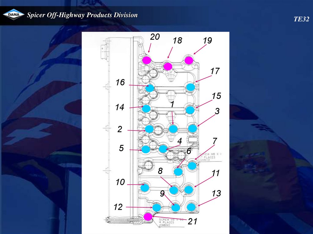
3. Hand tighten all bolts(21) according to the sequence you find on the drawing.
4. Torque all bolts 2X in the same sequence as on the drawing to 25Nm
5. Recalibrate the transmission
99.
Spicer Off-Highway Products DivisionTE32
20
18
19
17
16
15
1
14
3
2
4
5
7
6
8
11
9
13
10
12
21
100.
Spicer Off-Highway Products DivisionSpeed sensor installation
TE 32
101.
Spicer Off-Highway Products DivisionSpeed sensor installation
TE 32
102.
Spicer Off-Highway Products DivisionSpeed sensor installation
TE 32
103. APC200 CONTROLLER
Spicer Off-Highway Products DivisionAPC200 CONTROLLER
104.
OverviewLink with the transmission
APC200
APC200 display modes
APC200 diagnostics
System calibration
105.
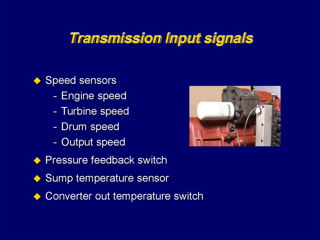
Transmission Input signalsSpeed sensors
- Engine speed
- Turbine speed
- Drum speed
- Output speed
Pressure feedback switch
Sump temperature sensor
Converter out temperature switch
106.
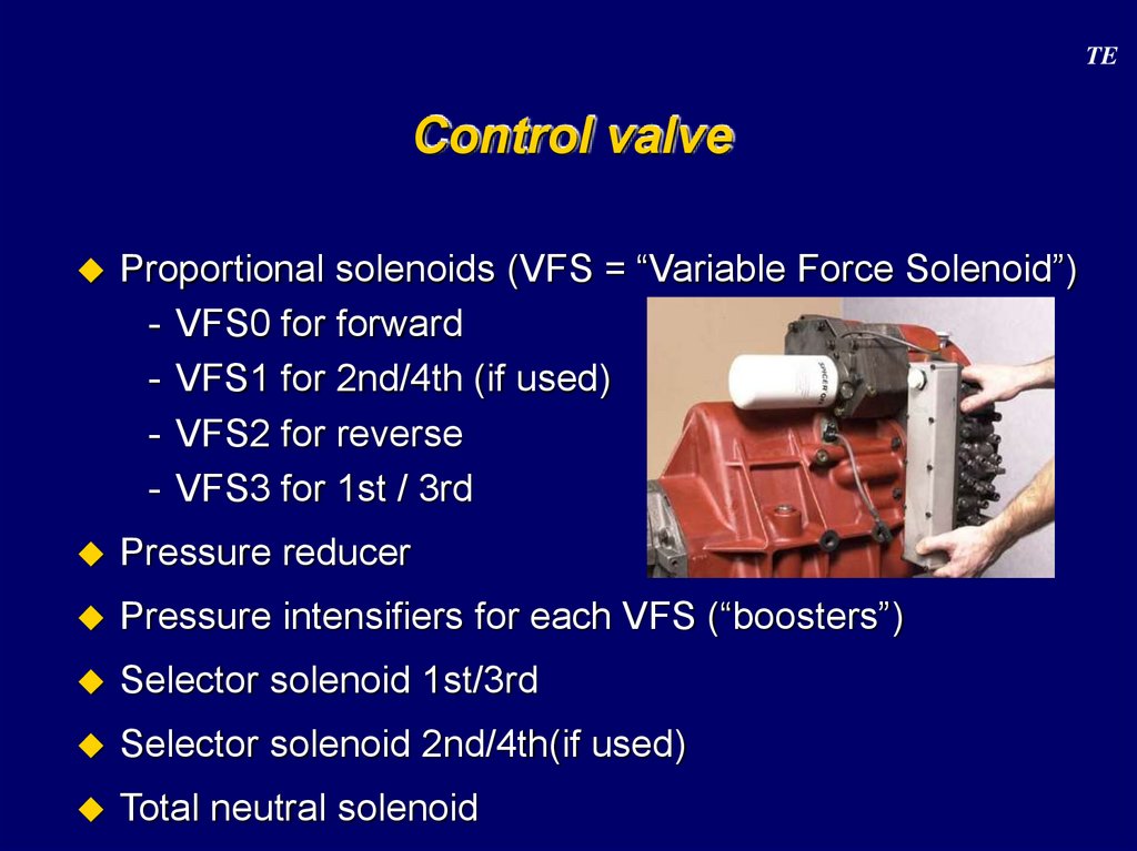
TEControl valve
Proportional solenoids (VFS = “Variable Force Solenoid”)
- VFS0 for forward
- VFS1 for 2nd/4th (if used)
- VFS2 for reverse
- VFS3 for 1st / 3rd
Pressure reducer
Pressure intensifiers for each VFS (“boosters”)
Selector solenoid 1st/3rd
Selector solenoid 2nd/4th(if used)
Total neutral solenoid
107. APC 200
ControllerAPC 200
Device for shifting Spicer Off Highway Products ECM powershift
transmissions (TE transmissions)
ECM -> Electronic Controlled Modulation
- a transmission control technology, available on a range of
transmission models
ECI -> Electronic Controlled Inching
- to run at very low controlled speed at virtually any engine speed
Overlap control
Self diagnostics
Throttle by Wire – engine control
CAN Network Integration
108. Block diagram APC 200
ControllerBlock diagram APC 200
Total Neutral
2/4 Sel
1/3 Sel
VFS Fwd
VFS 2nd/4th
VFS Rev
VFS 1st /3rd
Aux 1
Aux 2
Aux 3
Total Neutral
S
109. Block diagram APC 200 : inputs
ControllerBlock diagram APC 200 : inputs
10 digital inputs
6 (7) analogue inputs
- Ani0 Pressure feedback switch (resistance)
- Ani1 Sump temperature (resistance)
- Ani2 Converter out temperature switch (voltage)
- Ani3 Aux f.ex. brake pedal (voltage)
- (Ani4 Aux1 of anal. outputs (-pin) (reference voltage 5V))
- Ani5 Aux2 of anal. outputs (-pin) f.ex. servo feedback (voltage)
- Ani6 Aux3 of anal. outputs (-pin) f.ex. throttle pedal (voltage)
- input 0 to 2 have a fixed use
- input 3, 5 and 6 can be linked to external devices
4 speed inputs
110. Block diagram APC 200 : outputs (1/3)
ControllerBlock diagram APC 200 : outputs (1/3)
4 digital outputs
- Do0 RSP Drive Solenoid +
- Do1
• 2nd/4th selector (VFS1 is used for 2nd & 4th) on 4-speed
• can be used for warning lamp on 3-speed transm. (Kalmar)
- Do2 1st/3rd selector (VFS3 is used for 1st & 3rd)
- Do3 RSP Drive Solenoid -
111. Block diagram APC 200 : outputs (2/3)
ControllerBlock diagram APC 200 : outputs (2/3)
Do0 and Do3 : RSP Drive Solenoid = “Total neutral” solenoid
RSP = Redundant ShutDown Path
need of a fully reliable device to cut off pressure of all clutches in case
of important failures (shutdown)
Scheme :
24V
Do0
Total neutral sol. (valve)
Do3
APC200
112. Block diagram APC 200 : outputs (3/3)
ControllerBlock diagram APC 200 : outputs (3/3)
7 analogue outputs
- Closed loop current regulation for the VFS’s :
• VFS0 (fwd)
• VFS1 (2nd/4th)
• VFS2 (rev)
• VFS3 (1st/3rd)
- Aux1 to Aux3 : open loop current regulation
• VFS4+ (servomotor engine control A)
• VFS5+ (servomotor engine control B)
• VFS6+ (analogue brake valve)
- Remark servomotor : hardware version with H-bridge requested
113. Block diagram APC 200 : example
ControllerBlock diagram APC 200 : example
WIRE
A01
A02
A03
A04
A05
A06
A07
A08
A09
A10
A11
A12
A13
A14
A15
A16
A17
A18
A19
A20
A21
A22
A23
A24
A25
A26
A27
A28
A29
B00
A1
A2
A3
A4
A5
A6
A7
A8
A9
A10
A11
A12
A13
A14
A15
A16
A17
A18
A19
A20
A21
A22
A23
A24
A25
A26
A27
A28
A29
A30
PIN
A1
B1
C1
D1
E1
F1
G1
H1
J1
K1
A2
B2
C2
D2
E2
F2
G2
H2
J2
K2
A3
B3
C3
D3
E3
F3
G3
H3
J3
K3
FUNC
PPWR
VFS0+
VFS0VFS1+
VFS1VFS2+
VFS2VFS3+
VFS3DO0
ANI0
DIGIN0
DIGIN1
DIGIN2
DO1
DO2
DIGIN3
DIGIN4
DIGIN5
DO3
GND
SS0
SS0
SS1
SS1
SS2
SS2
ANI1
ANI2
GND
TYPE
Pwr
Pwm
Sns
Pwm
Sns
Pwm
Sns
Pwm
Sns
Stp
Ptg
Ptp
Ptp
Ptp
Stp
Stp
Ptp
Ptp
Ptp
Stg
Gnd
Sns
Gnd
Sns
Gnd
Sns
Gnd
Ptg
Ptg
Gnd
DESCRIPTION 3/3 & 4/4 SPEED
Permanent Battery Plus
Fwd VFS Hi Side Out
Fwd VFS Lo Side In
2nd/4th VFS Hi Side Out
2nd/4th VFS Lo Side In
Rev VFS Hi Side Out
Rev VFS Lo Side In
1th/3th VFS Hi Side Out
1th/3th VFS Lo Side In
RSP Drive Solenoid +
Pressure feedback
Shiftlever 1-2
Shiftlever 2-3
Shiftlever 3-4
2/4 VFS selector or alarm output
1/3 VFS selector
Shiftlever NEU
Shiftlever FWD
Shiftlever REV
RSP Drive Solenoid Supply ground
Drum speed sensor+
Drum speed sensor Output speed sensor+
Output speed sensor Engine speed sensor+
Engine speed sensor TransmTemperature
Cooler input temperature
Signal ground
WIRE
B01
B02
B03
B04
B05
B06
B07
B08
B09
B10
B11
B12
B13
B14
B15
B16
B17
B18
B1
B2
B3
B4
B5
B6
B7
B8
B9
B10
B11
B12
B13
B14
B15
B16
B17
B18
PIN
L1
M1
N1
P1
R1
S1
L2
M2
N2
P2
R2
S2
L3
M3
N3
P3
R3
S3
FUNC
VFS4+
ANI4
VFS5+
ANI5
VFS6+
ANI6
CANL
CANH
RXD
TXD
SS3
SPWR
DIGIN6
DIGIN7
DIGIN8
DIGIN9
ANI3
SGND
TYPE
HbrgA
Sns
HbrgB
Sns
Pwm
Sns
Comm
Comm
Comm
Comm
Sns
Pwr
Ptp
Ptp
Ptp
Ptp
Ptg
Gnd
DESCRIPTION 3/3 & 4/4 SPEED
Engine control motor A
5V Reference voltage out
Engine servo motor B
Engine servo pos. input 0-5V
Analog brake valve
Accelerator pedal analog input 0-5V
CAN Lo
CAN Hi
RS232 RXD
RS232 TXD / SPEEDO OUT
Turbine speed sensor+
Switched Battery Plus
Inching Enable switch
manual / automatic selection
Parking Brake OFF/ON
Brake pedal analog input 0-5V
Signal Ground
114. PSU = Power Supply Unit
ControllerPSU = Power Supply Unit
Version : 12V or 24V
Two power lines
- PPWR : permanent power
• Connected directly to the battery
- SPWR : switched power
• Connected via key contact to the battery
115. Bootstrap and reset circuit
ControllerBootstrap and reset circuit
Bootstrap:
- Special mode, controller wants to receive serial data, to
program the firmware into the program memory
- While in bootstrap all output functions are hold off
- Start : during power up both buttons pressed
Reset circuit : watchdog & supply supervisor will reset the
CPU if either the feedback from the watchdog is outside
10% of timing tolerance or if the CPU has “forgotten” to retrigger the watchdog trigger
116. Functions
ControllerFunctions
Manual / automatic shifting
Electronic modulation
Overlap control
Electronic inching
Start 1st / 2nd
Limit vehicle speed
Reduce vehicle speed (by use of an input)
Limit engine speed
Direction change protection (speed and engine RPM)
Declutch (in normal mode : neutral / in inching : offset pressure)
Engine control
Seat orientation
Hydro lever function in neutral
117.
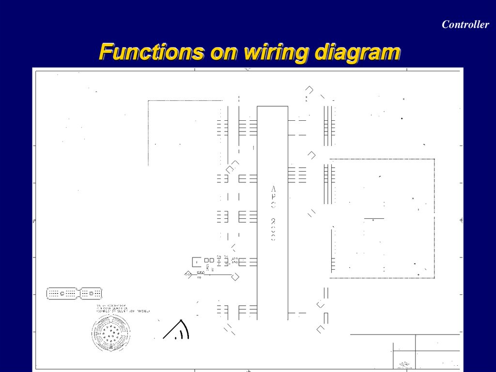
ControllerFunctions on wiring diagram
118. Communication
ControllerCommunication
CAN 2.0 B
- Communicate with different controllers and PC
RS 232
- To flash a new firmware (main program)
- To download the parameter settings (APT-file)
- To edit specific parameters (GDE-file)
119. Parameter setting
ControllerParameter setting
1 approved drive-line = 1 APT-file
Approved drive-line =
Specific type of vehicle + specific engine + specific
transmission ( + axle + tires )
120. Display
ControllerDisplay
- 4 red 7-segment LED digits
- 3 status LED lamps
• D -> yellow, test modes
• E -> yellow, faults
• F -> red, APC 200 in reset conditions (f.ex. bootstrap)
- 2 push buttons
• M -> which information group
• S -> item within group
121. Display modes
ControllerDisplay modes
M
S
M
M
S
S
122. Display modes
ControllerDisplay modes
“GPOS” display
- Reflects the actually engaged transmission direction
and range
123. Display modes
ControllerDisplay modes
“VSPD” display
- Shows the vehicle speed in km/h or MPH, with a
resolution of 0.1 km/h or 0.1 MPH
124. Display modes
ControllerDisplay modes
“dist” display
- Shows the distance travelled in km or miles, with a
resolution of 0.1 km or 0.1 miles
Note : the distance can be reset by pushing the “s” button during 3
seconds when being in this display mode.
125. Display modes
ControllerDisplay modes
M
S
M
M
S
S
126. Display modes
ControllerDisplay modes
“CPOS” display
- Reflects the actually shiftlever position
127. Display modes
ControllerDisplay modes
“Espd” display
- Shows the measured engine speed in RPM
128. Display modes
ControllerDisplay modes
“Tspd” display
- Shows the measured turbine speed in RPM
129. Display modes
ControllerDisplay modes
“Ospd” display
- Shows the measured output speed in RPM
130. Display modes
ControllerDisplay modes
“Srat” display
- Reflects the current speed ration ( Tspd / Espd ), which
is an important factor in automatic shifting
131. Display modes
ControllerDisplay modes
“TQ I” display
- Reflects the measured torque (turbine torque) at the
transmission input side in Nm
132. Display modes
ControllerDisplay modes
“Ttmp” display
- Shows the transmission sump temperature in °C
133. Display modes
ControllerDisplay modes
“Ctmp” display
- Shows the Converter out temperature in °C
Note : due that the converter out temperature is measured by a
temperature switch : 50 on the display means below 120° C
150 on the display means above 120° C
134. Display modes
ControllerDisplay modes
M
S
M
M
S
S
135. Display modes
ControllerDisplay modes
“Err” display
- Shows all existing error codes (none blinking error
code) and error codes detected in the past (blinking
error code).
(none blinking)
S
(blinking)
S
Note : when an error is active,
the error led will be blinking
(end of faults)
136. Error codes list
ControllerError codes list
137. Diagnostics
ControllerDiagnostics
M
M
M
M
M
M
S
S
S
S
S
S
S
S
S
S
S
S
S
S
S
S
S
S
Power up
+ S
S
S
...
S
...
S
...
S
S
S
...
S
S
S
S
S
S
138. Diagnostics
ControllerDiagnostics
M
M
M
M
M
M
S
S
S
Power up
+ S
Display test
Note : for the firmware version, the display is using a
scrolling text moving to the left (continuously).
139. Diagnostics
ControllerDiagnostics
M
M
M
M
M
M
S
S
0
2 4
6 8
10 12
1
3 5
7 9
11 13
S
Digital input
test
Digital input
reference
Digital
input 3 on
wire 17
S
...
S
S
input not
Note : input 10 till 13 are the 4 analog
inputs, which could be used as
active
digital inputs
140. Diagnostics
ControllerDiagnostics
M
M
M
M
M
M
S
S
Analog input
test
No . meaning the
value is in
S
S
...
S
1st value (k or V) of the
1st 4 analog inputs
S
A . meaning the
value is in Volts
Analog input
3 on wire 47
(47 – 30 pins on
connector A = B17)
141. Diagnostics
ControllerDiagnostics
M
M
M
M
M
M
S
S
Speed sensor test
S
Speed sensor
0 on wire 22
S
...
C informs the
sensor is a current
sensor, value is
expressed in Hz or
kHz (ex.: c2.45)
S
1st value (kHz) of the 4
speed sensors
S
142. Diagnostics
ControllerDiagnostics
M
M
M
M
M
M
S
S
Analog output
3 on wire 8
Output test
S
Analog output
Current of 997 mA
S
...
S
output active
Digital output
1 (7 – 6 = 1 ) on
wire 10
S
Note : 0 till 6 are
analog
outputs, and
7 till 10 are
digital
outputs.
143. Diagnostics
ControllerDiagnostics
M
M
M
M
M
M
S
S
Voltage test
Voltage switched
power
S
22.7 volt
S
8.1 volt
Voltage sensor
power supply
144. Calibration APC200-Transmission
Spicer Off-Highway Products DivisionCalibration APC200-Transmission
Menu structure overview
Transmission calibration (clutch filling)
Heat mode
Calibration of the analogue inputs :
- Throttle pedal
- Brake pedal
- Hydro lever
- Servo motor
145. Menu structure overview
Spicer Off-Highway Products DivisionMenu structure overview
146. Transmission calibration (clutch filling) Introduction
Spicer Off-Highway Products DivisionTransmission calibration (clutch filling)
Introduction
What?
Is determining volume of oil that is needed to fill up the
clutch, untill clutch plates start to transfer torque.
This start of torque transfer is the point when the
programmed modulation curve starts to act.
Since each transmission, clutch ,valve and VFS has its own
tolerances, this fill capacity needs to be determined on
newly assembled units and every time any of these
components is changed.
147. Transmission calibration (clutch filling) Introduction
Spicer Off-Highway Products DivisionTransmission calibration (clutch filling)
Introduction
How ?
Direction (FWD/REV)clutches are calibrated by fully
activating 2nd range clutch, and then by gradually
increasing the pressure signal from the directionalVFS untill
a drop in turbine RPM is noted. This drop in turbine RPM is
the touch detection i.e. the point at which the clutch starts to
transfer torque. This VFS signal is stored in the memory of
the APC200 and is used as the start point for the modulation
which was predetermined during prototype testing.
Range clutches (1st, 2nd,3th and 4th ) are calibrated by fully
activating forward clutch and then by gradually increasing
the pressuure signal to the corresponding range VFS as
above.
148. Transmission calibration (clutch filling) Introduction
Spicer Off-Highway Products DivisionTransmission calibration (clutch filling)
Introduction
A transmission calibration has to be performed :
- when the vehicle is built at the OEM
- after 2000 hours driving in gear (forward or reverse)
- when the valve is changed
- when an overhaul of the transmission is done
- when the transmission is repaired / replaced
- when the APC200 is replaced
- when firmware and APT-file are updated
Goal :
- guarantee the best shift quality during the complete life
of the transmission
149. Transmission calibration (clutch filling) How ? (1/3)
Spicer Off-Highway Products DivisionTransmission calibration (clutch filling)
How ? (1/3)
Enter the calibration menu by pressing the S-button on the
APC200 display for 15 s during power up of the APC :
Push the S-button to trigger the transmission calibration
Before the calibration can be started, a number of
conditions need to be fulfilled :
- parking brake has to be activated
- sump temperature has to be > 60°C (cfr. Heat mode)
- engine speed has to be kept within 800 200 rpm (note: if the APC
has control over the engine, the speed will be adapted
automatically)
150. Transmission calibration (clutch filling) How ? (2/3)
Spicer Off-Highway Products DivisionTransmission calibration (clutch filling)
How ? (2/3)
If all these conditions are met, the APC will ask to shift to
forward to start the calibration :
The transmission calibration now starts. This is indicated on
the APC200-display :
etc. (‘c1’ = clutch 1 I.e. fwd ; ‘M1’ = mode 1 of the calibration)
151. Transmission calibration (clutch filling) How ? (3/3)
Spicer Off-Highway Products DivisionTransmission calibration (clutch filling)
How ? (3/3)
When all clutches have been calibrated, the APC200
displays :
This means the calibration has been completed successfully. Normal duration : about 15 min.
Now switch off the ignition key of the vehicle and let the APC
power down.
When restarting the vehicle, the calibration results will be
activated automatically.
Important : by selecting REVERSE, the calibration is
stopped immediately (APC powers down).
152. Heat mode (1/3)
Spicer Off-Highway Products DivisionHeat mode (1/3)
Goal : warm up transmission in a fast way (stall)
Specific to heat mode :
- fwd/rev can be selected while the parking brake is on
- disables inching and declutch
- the highest gear is forced (3rd or 4th)
How ? Push M-button when ‘trAn’ is on the display :
Push the S-button to trigger the heat mode : actual sumpt°
153. Heat mode (2/3)
Spicer Off-Highway Products DivisionHeat mode (2/3)
Perform the following scheme to warm up the transmission :
When the sumpt° is above 60°C, the indication on the APC
display starts blinking.
Now push the M-button until you come back to ‘trAn’
154. Heat mode (3/3)
Spicer Off-Highway Products DivisionHeat mode (3/3)
Note : When the converter out temperature would exceed
120°C, the engine speed will be limited to half throttle (if
APC has engine control) or the transmission will be forced to
neutral (when APC has no engine control).
155. Other messages during calibration (1/5)
Spicer Off-Highway Products DivisionOther messages during calibration (1/5)
1. Calibration condition messages
156. Other messages during calibration (2/5)
Spicer Off-Highway Products DivisionOther messages during calibration (2/5)
1. Calibration condition messages (part 2)
157. Other messages during calibration (3/5)
Spicer Off-Highway Products DivisionOther messages during calibration (3/5)
2. Calibration error messages
E1.25 : during calibration, early touch detect.
Possible causes :
Too much clutch drag because of too thick oil, recalibrate at higher
temperature 90 -100 °C)
Sticking or burnt clutch which causes turbine to drop before pressure
is applied,
E1.26 : during calibration,no touch detect.
Possible causes :
VFS faulty (no out put pressure)
Slipping clutch or too high internal leakage
158. Other messages during calibration (4/5)
Spicer Off-Highway Products DivisionOther messages during calibration (4/5)
2. Calibration error messages continued
E1.10 : during calibration, shift inhibit.
Possible causes :
Caused by shutdown e.g; in combination with 20/60 error;
Resolve cause of shutdown before recalibation
159. Other messages during calibration (5/5)
Spicer Off-Highway Products DivisionOther messages during calibration (5/5)
2. Calibration error messages continued
E2.14 : calibration failed ,fill time out.
Possible causes :
Turbine speed does not decrease caused by too high internal
leakage and or slipping clutch
E2.16 : calibration failed , turbine pull down too early.
Possible causes :
Faulty turbine speed sensor
160. Calibration of analogue imputs Example : brake pedal (1/4)
Spicer Off-Highway Products DivisionCalibration of analogue imputs
Example : brake pedal (1/4)
Enter the calibration menu by pressing the S-button on the
APC200 display for 15 s during power up of the APC.
When having ‘trAn’ on the display, push the M-button until
you see
Push the S-button to trigger the brake pedal calibration
The APC now asks for the idle position of the brake pedal
(no play in the pedal anymore) :
Push the S-button to confirm the position.
161. Calibration of analogue imputs Example : brake pedal (2/4)
Spicer Off-Highway Products DivisionCalibration of analogue imputs
Example : brake pedal (2/4)
Then, the APC asks for the mid position of the brake pedal
(point where the brakes start to operate) :
With hydraulic brakes : this point corresponds to the
moment the brakes start ‘sissing’
With dry brakes : push the pedal a little bit, just enough to
make the position led stop blinking (if blinking, there is not
enough position difference / former position). When doing
so, the midpoint is automatically clipped at 5%.
Push again the S-button to confirm the position.
162. Calibration of analogue imputs Example : brake pedal (3/4)
Spicer Off-Highway Products DivisionCalibration of analogue imputs
Example : brake pedal (3/4)
Finally, the APC asks for the full brake position :
Apply full brake and press the S-button to confirm.
If the calibration has been successful, the APC display will
show
Now switch off the contact key. The calibration values are
automatically stored into the APC200.
163. Calibration of analogue imputs Example : brake pedal (4/4)
Spicer Off-Highway Products DivisionCalibration of analogue imputs
Example : brake pedal (4/4)
164. TE transmission field experience
Spicer Off-Highway Products DivisionTE transmission field experience
TE13/17 field campaign
Speed sensor changes
Case studies
165. TE transmission field experience
Spicer Off-Highway Products DivisionTE transmission field experience
TE13/17 field campaign
Clutch end plate snapring jumps out of groove, causing
slipping clutch.
Only cluthes in combination with a spacer between endplate
and snapring are affected
Fix is a one piece endplate
Population : all units built prior to April 2004
166. TE transmission field experience
Spicer Off-Highway Products DivisionTE transmission field experience
Speed sensor changes.
Cracked speedsensor housing causes potting material to
swell which results in speed sensor touching the gear.
solved by changing potting material and new speed sensors
moulds
Latest version is recognisable by a coloured ring around the
housing
Installation : refer to drawing
167. TE transmission field experience
Spicer Off-Highway Products DivisionTE transmission field experience
Case
studies
1. Vehicle stops error 00.50
action 1 : Change APC and calibrate
error E1.25 and E2.14 in 2nd
vehicle only drives in second
action 2 : changed valve and recalibrate
error 20.60 before calibration can start
action 3 : measure cluch pressure ( 0 bar), measure lube pressure
(0bar), check pump (OK) found sandwich plate on valve not fitted during
exchange, refitted sandwich plate and recalibrate
error E1.25 and E2.14
vehicle only drives in 2nd and blocks in 1st and 3rd
action 4 : replace transmission, faulty unit had a burnt 2nd clutch
Comments, A 20/60 error indicates a system pressure fault, 1st step
should be to check system pressure
168. TE transmission field experience
Spicer Off-Highway Products DivisionTE transmission field experience
Case
studies
2. Vehicle has a delay when downshifting, no error codes
action 1 : replace speed sensors and valve
no improvement
action 2 : test drive confirms that downshiftspeedpoints are lower than
on similar vehicle, recalibrate throttle switch
No improvement
action 3 : test drive shows that speed ratio and turbine speeds are
correct when down shift is made, indicating a changed converter
characteristic which causes loss of tractive effort ; measure stall speed
which shows only 1200 RPM i.o. 1800 RPM.
Replace transmission which shows a failed converter freewheel
Comments: the delay was not clearly understood. This case proofs that
basic converter/transmission troubleshooting is still valid (measure stall
speed),
169. TE transmission field experience
Spicer Off-Highway Products DivisionTE transmission field experience
Case
studies
3. Tel call : machine sometimes shows 20.60error code
action 1 : recalibrate transmission
Error codes : E1.26; E2.14
vehicle symptons : slips in third, oil is contaminated
replace transmission which shows a 3 rd clutch failure
commnets, The 20/60 appeared only when 3rd clutch is selected, this
indicates a high 3rd clutch leakage? The symptons confirm this;
behind the 20/60 error a 42.05 should have been found, but this was not
checked.
A 20/60 only on TE32 can also indicate that two range or direction
cluthes are engaged at the same time. Pressure checks should confirm
this .
170. TE transmission field experience
Spicer Off-Highway Products DivisionTE transmission field experience
Case studies
4. Tel call : unit shocks when 4th is selected and goes back to 3rd , no error codes
action 1 check 4th clutch pressure : 5 bar
action remove transmission and send for repair
nothing found wrong, reinstalled unit and is OK… for 2 days when
problem reappears
action 2 : check CPOS and GPOS on APC200
CPOS shows only FWD 3
action 3 : replace cab control
Problem solved
comments : The cab control had an intermittent fault causing 4th to engage and
disengage; this causes the VFS 4/2 to rise and fall in pressure quickly which
explains the 5 bar measured . The suspected 4 th clutch failure should have
been confirmed by error codes.
171. TE transmission field experience
Spicer Off-Highway Products DivisionTE transmission field experience
Case
studies
5. Tel call : failure code 20/61 with engine not running
pressure switch blocked in closed position.
Action 1 : replace pressure switch
problem solved
comment : 20/61 indicates system pressure when it should not be there.
Since engine is not running there can be no system pressure indicating
a jammed switch
If 20/61 occurs with engine running it is most probably caused by a
faulty engine speed sensor which generates 0 RPM
172. TE transmission field experience
Spicer Off-Highway Products DivisionTE transmission field experience
Case
studies
6. Tel call : error code 42/04 (speed ratio (Turbine/Output) too low
action 1 replace turbine speed sensor
Problem solved
comment : too low speed ratio is a wrong speed measurement or a
wrong ratio. Since a wrong ratio is least likely the turbine or output
speed sensor are at fault
42/05 error (speed ratio too high) can be caused by the same speed
sensors if this fault appears in all speeds/directions. If it only appears in
one speed or one direction you have to assume a slipping clutch.
173.
Spicer Off-Highway Products DivisionThanks