


 Интернет
Похожие презентации:


VLANs. Lecture 3
1.
Lecture 3VLANs
1
2.
Objectives1. Describe Virtual Local Area
Network (VLAN)
2. Configure network topology
2
3.
VLANs1. Describe Virtual Local Area
Network (VLAN)
3
4.
Broadcast DomainsA broadcast domain is simply a group of devices that are on the same
network, capable of receiving and responding to a broadcast frame from any
device. A broadcast message uses a special Layer-2 MAC address:
FF:FF:FF:FF:FF:FF and a special Layer-3 IPv4 address: 255.255.255.255.
In Figure, Host A transmits a broadcast address. Perhaps it is saying, “Hey
everyone! Who has IP address 10.1.1.12” Because switch SW1 forwards this
out all other ports, hosts B and C receive the message. Of course, nobody in
broadcast domain 2 receives the message - they are not even connected!
4
5.
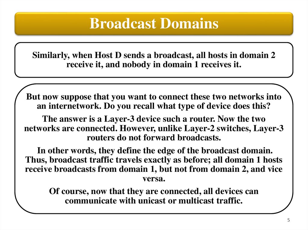
Broadcast DomainsSimilarly, when Host D sends a broadcast, all hosts in domain 2
receive it, and nobody in domain 1 receives it.
But now suppose that you want to connect these two networks into
an internetwork. Do you recall what type of device does this?
The answer is a Layer-3 device such a router. Now the two
networks are connected. However, unlike Layer-2 switches, Layer-3
routers do not forward broadcasts.
In other words, they define the edge of the broadcast domain.
Thus, broadcast traffic travels exactly as before; all domain 1 hosts
receive broadcasts from domain 1, but not from domain 2, and vice
versa.
Of course, now that they are connected, all devices can
communicate with unicast or multicast traffic.
5
6.
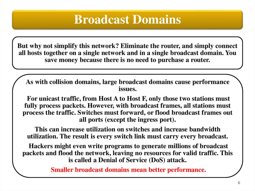
Broadcast DomainsBut why not simplify this network? Eliminate the router, and simply connect
all hosts together on a single network and in a single broadcast domain. You
save money because there is no need to purchase a router.
As with collision domains, large broadcast domains cause performance
issues.
For unicast traffic, from Host A to Host F, only those two stations must
fully process packets. However, with broadcast frames, all stations must
process the traffic. Switches must forward, or flood broadcast frames out
all ports (except the ingress port).
This can increase utilization on switches and increase bandwidth
utilization. The result is every switch link must carry every broadcast.
Hackers might even write programs to generate millions of broadcast
packets and flood the network, leaving no resources for valid traffic. This
is called a Denial of Service (DoS) attack.
Smaller broadcast domains mean better performance.
6
7.
Virtual LANRecall that if a switch receives a broadcast on any port, it floods it out all
other ports, except the ingress port. Therefore, if Host A in Figure sends
a broadcast, the LAN-A switch forwards it out all other ports and so
host B receives the frame. Of course, hosts D and E do not receive this
frame, there is no connection between LAN-A and LAN-B. They are
physically separate LANs, connected to physically separate switches.
7
8.
Virtual LANWhat if you wanted to connect these three Local Area Networks into
an Internetwork?
Simply add a router, which can route unicast and multicast traffic
between the LANs.
Now consider a Virtual LAN (VLAN), which is, just like a physical
LAN, a group of devices in the same broadcast domain. Suppose that
you have a single, physical Aruba switch named SW1.
In Figure, hosts A to E connect to ports 1, 2, 11, and 12 on this switch.
By default, all these devices are in the same broadcast domain. If
Host A sends a broadcast, all other hosts receive the frame. Now
suppose that you learned some new switch syntax, and created a
Virtual LAN named “VLAN1O”
8
9.
Virtual LANIt is as if you have created a small virtual switch, inside the physical
switch. This virtual switch exists, but it is not connected to any of the
physical switch ports.
Therefore, you can define or “map” physical ports 1 and 2 as being
members of the red VLAN 10.
Similarly, you create VLAN20, and assign ports 11 and 12 as
members of the blue VLAN 20.
You have now created two separate broadcast domains on a single
physical switch. When host A sends a broadcast, the switch knows to
only forward that frame out all ports that are in the same VLAN,
except the ingress port. Only host B receives the broadcast. If host D
broadcasts, only E receives it.
9
10.
Virtual LANYou have effectively recreated the scenario on the left,
using a single physical switch. Just like the physical
scenario on the left, there is NO connectivity between the
separate VLANs. No unicast, multicast, nor broadcast
traffic shall pass between the VLANs.
Of course, you could always connect a router to create an
internetwork, just like you did with the physical switches.
But if the scenarios operate in the same way, why bother
with VLANs? Let us talk about the advantages of VLANs
and learn some new syntax.
10
11.
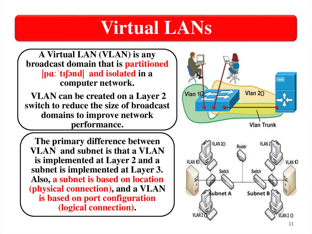
Virtual LANsA Virtual LAN (VLAN) is any
broadcast domain that is partitioned
|pɑːˈtɪʃənd| and isolated in a
computer network.
VLAN can be created on a Layer 2
switch to reduce the size of broadcast
domains to improve network
performance.
The primary difference between
VLAN and subnet is that a VLAN
is implemented at Layer 2 and a
subnet is implemented at Layer 3.
Also, a subnet is based on location
(physical connection), and a VLAN
is based on port configuration
(logical connection).
0
0
0
0
0
Subnet A
0
Subnet B
0
11
12.
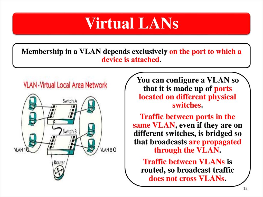
Virtual LANsMembership in a VLAN depends exclusively on the port to which a
device is attached.
0
0
You can configure a VLAN so
that it is made up of ports
located on different physical
switches.
Traffic between ports in the
same VLAN, even if they are on
different switches, is bridged so
that broadcasts are propagated
through the VLAN.
Traffic between VLANs is
routed, so broadcast traffic
does not cross VLANs.
12
13.
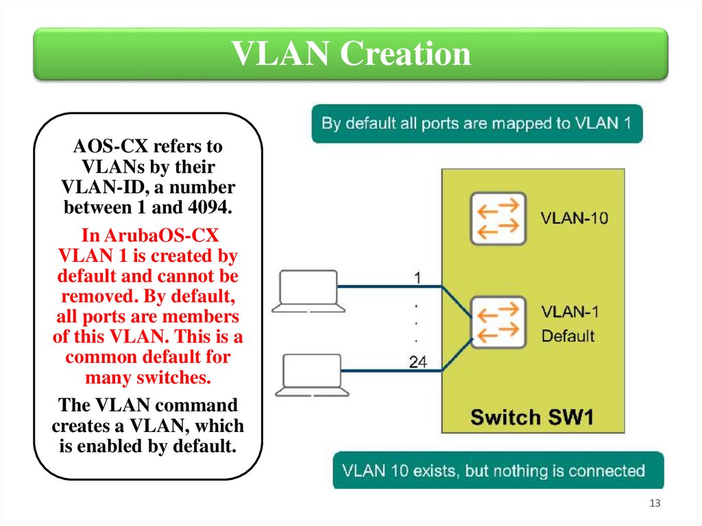
VLAN CreationAOS-CX refers to
VLANs by their
VLAN-ID, a number
between 1 and 4094.
In ArubaOS-CX
VLAN 1 is created by
default and cannot be
removed. By default,
all ports are members
of this VLAN. This is a
common default for
many switches.
The VLAN command
creates a VLAN, which
is enabled by default.
13
14.
Virtual LANs (VLANs) TypesDefault
VLAN
• Includes all switch ports when a switch is
in its default configuration. In the
default configuration, the default VLAN
carries both management traffic and
standard network traffic.
Primary
VLAN
• Initially the default VLAN. For HP
switches, the primary VLAN is the only
VLAN on the switch that can receive a
switch‐generated address via DHCP.
• You can designate a custom VLAN as
the primary VLAN and make it
responsible for some management
functions.
14
15.
Virtual LANs (VLANs) TypesManagement
VLAN
• Management VLAN is used for
managing the switch from a
remote location by using protocols
such as telnet, SSH, SNMP, syslog
etc.
• Normally the Management VLAN
is VLAN 1, but you can use any
VLAN as a management VLAN.
• To identify a specific VLAN as the
only VLAN from which users can
connect to the switch management
interface.
15
16.
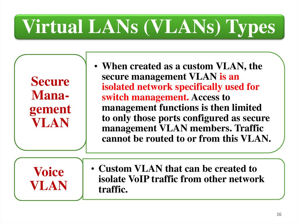
Virtual LANs (VLANs) TypesSecure
Management
VLAN
• When created as a custom VLAN, the
secure management VLAN is an
isolated network specifically used for
switch management. Access to
management functions is then limited
to only those ports configured as secure
management VLAN members. Traffic
cannot be routed to or from this VLAN.
Voice
VLAN
• Custom VLAN that can be created to
isolate VoIP traffic from other network
traffic.
16
17.
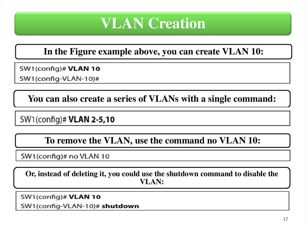
VLAN CreationIn the Figure example above, you can create VLAN 10:
You can also create a series of VLANs with a single command:
To remove the VLAN, use the command no VLAN 10:
Or, instead of deleting it, you could use the shutdown command to disable the
VLAN:
17
18.
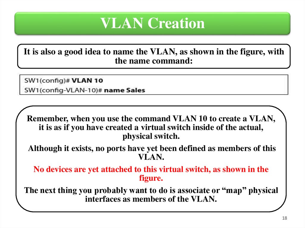
VLAN CreationIt is also a good idea to name the VLAN, as shown in the figure, with
the name command:
Remember, when you use the command VLAN 10 to create a VLAN,
it is as if you have created a virtual switch inside of the actual,
physical switch.
Although it exists, no ports have yet been defined as members of this
VLAN.
No devices are yet attached to this virtual switch, as shown in the
figure.
The next thing you probably want to do is associate or “map” physical
interfaces as members of the VLAN.
18
19.
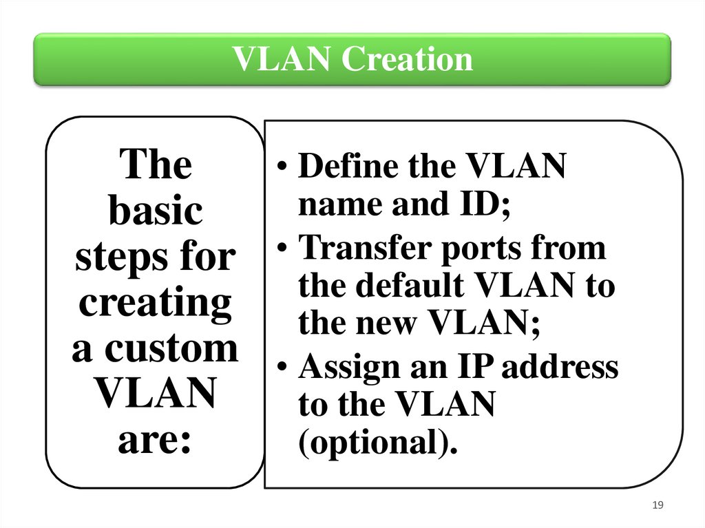
VLAN Creation• Define the VLAN
The
name and ID;
basic
steps for • Transfer ports from
the default VLAN to
creating the new VLAN;
a custom • Assign an IP address
VLAN
to the VLAN
are:
(optional).
19
20.
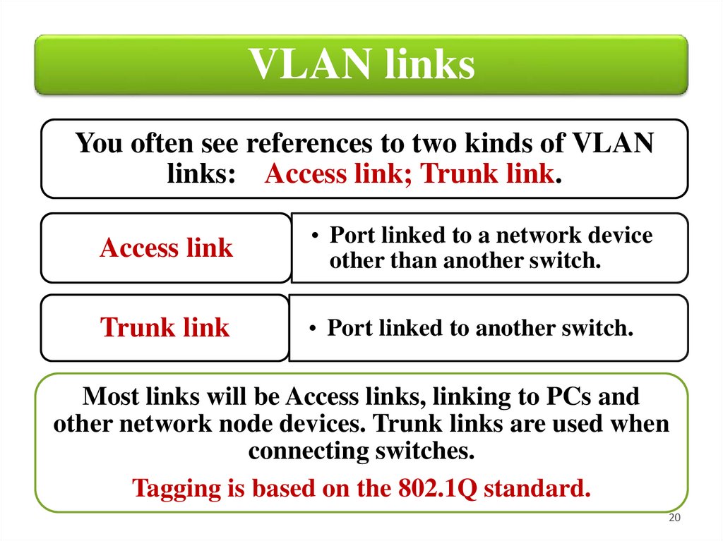
VLAN linksYou often see references to two kinds of VLAN
links: Access link; Trunk link.
Access link
• Port linked to a network device
other than another switch.
Trunk link
• Port linked to another switch.
Most links will be Access links, linking to PCs and
other network node devices. Trunk links are used when
connecting switches.
Tagging is based on the 802.1Q standard.
20
21.
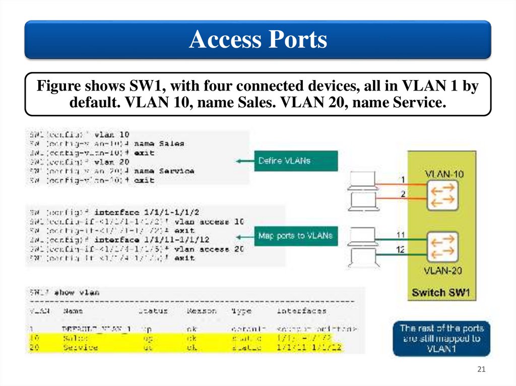
Access PortsFigure shows SW1, with four connected devices, all in VLAN 1 by
default. VLAN 10, name Sales. VLAN 20, name Service.
21
22.
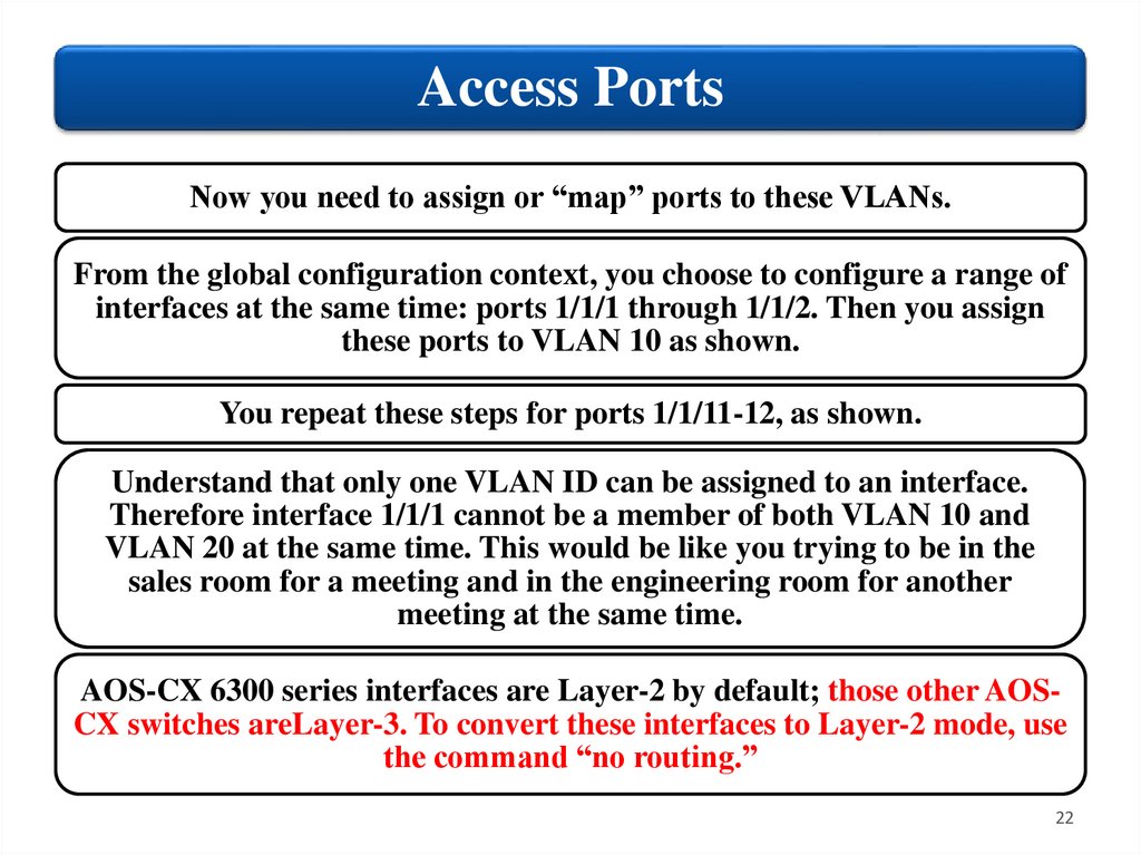
Access PortsNow you need to assign or “map” ports to these VLANs.
From the global configuration context, you choose to configure a range of
interfaces at the same time: ports 1/1/1 through 1/1/2. Then you assign
these ports to VLAN 10 as shown.
You repeat these steps for ports 1/1/11-12, as shown.
Understand that only one VLAN ID can be assigned to an interface.
Therefore interface 1/1/1 cannot be a member of both VLAN 10 and
VLAN 20 at the same time. This would be like you trying to be in the
sales room for a meeting and in the engineering room for another
meeting at the same time.
AOS-CX 6300 series interfaces are Layer-2 by default; those other AOSCX switches areLayer-3. To convert these interfaces to Layer-2 mode, use
the command “no routing.”
22
23.
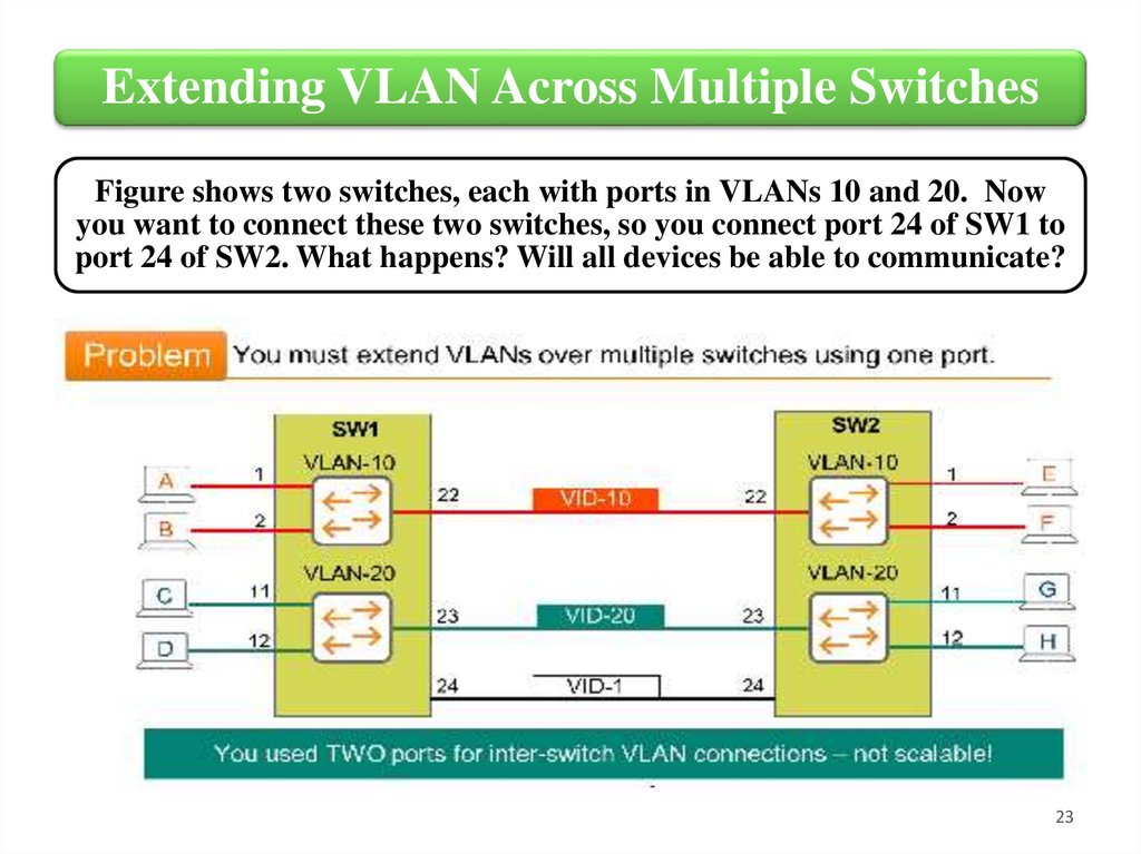
Extending VLAN Across Multiple SwitchesFigure shows two switches, each with ports in VLANs 10 and 20. Now
you want to connect these two switches, so you connect port 24 of SW1 to
port 24 of SW2. What happens? Will all devices be able to communicate?
23
24.
Extending VLAN Across Multiple SwitchesRecall that by default ports are members of VLANI, including port 24 on
both switches. This means that port 24 is not connected to VLANs 10 and
20, and so cannot carry that traffic. Effectively, you still do not have
connectivity between the switches for VLANs 10 and 20. How can we fix
this?
One way is to connect two more pairs of ports.
Map port 22 on both switches to VLAN 10, and port 23 as to VLAN 20. Now
all VLANs can communicate. A broadcast from host A is flooded out all
ports in VLAN 10 (except ingress port), and so all members of VLAN 10
receive the broadcast. This is good, but there is a problem.
You used up two physical ports on each switch. What if we had 100 VLANs?
We would need 100 physical switch ports just for interconnects, that is not
feasible.
We need a way to use one single physical port to connect multiple VLANs.
24
25.
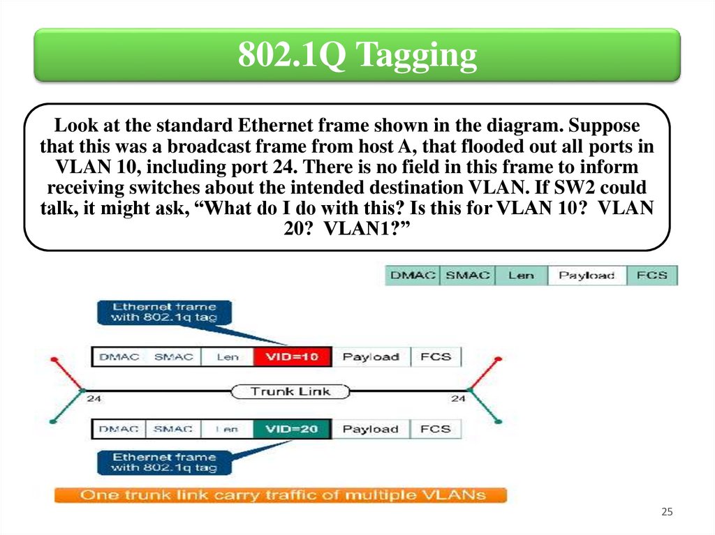
802.1Q TaggingLook at the standard Ethernet frame shown in the diagram. Suppose
that this was a broadcast frame from host A, that flooded out all ports in
VLAN 10, including port 24. There is no field in this frame to inform
receiving switches about the intended destination VLAN. If SW2 could
talk, it might ask, “What do I do with this? Is this for VLAN 10? VLAN
20? VLAN1?”
25
26.
802.1Q TaggingWe need a tagging mechanism, as defined in the IEEE 802.1Q standard.
This standard adds an additional 4 bytes field, the 802.1Q Tag field.
The most important part of this field (12 bits) is the VLAN tag or VLAN-ID
or simply VID.
Before SW1 floods this broadcast frame across this specially defined “trunk
port’, it adds this tag to the frame.
26
27.
802.1Q TaggingThus, SW2 receives the frame, looks at the tag, and knows:
“This frame is for VLAN 10”. It strips off the special tag, and
forwards a standard Ethernet frame out all ports in VLAN 10,
to hosts E and F.
Next host G sends a broadcast. SW2 floods a standard
Ethernet frame out its local ports. Before flooding the frame
out port 24, it is a tag, “This frame is for VLAN 20.” SW1
receives this frame, sees that it is for VLAN 20, strips off the
tag, and forwards a standard Ethernet frame out all ports in
VLAN 20 (11 and 12).
Thus, you can now extend the VLAN concept across multiple
switches, using a single physical port.
27
28.
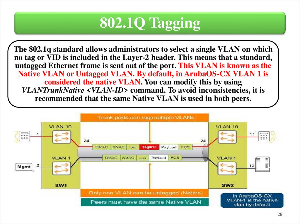
802.1Q TaggingThe 802.1q standard allows administrators to select a single VLAN on which
no tag or VID is included in the Layer-2 header. This means that a standard,
untagged Ethernet frame is sent out of the port. This VLAN is known as the
Native VLAN or Untagged VLAN. By default, in ArubaOS-CX VLAN 1 is
considered the native VLAN. You can modify this by using
VLANTrunkNative <VLAN-ID> command. To avoid inconsistencies, it is
recommended that the same Native VLAN is used in both peers.
28
29.
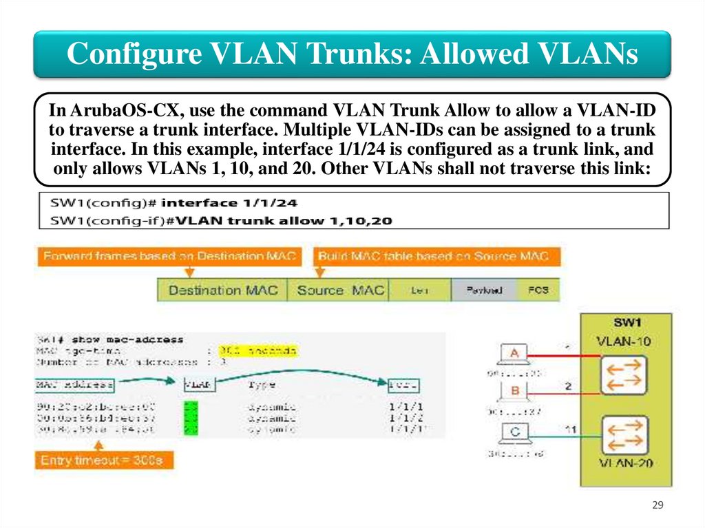
Configure VLAN Trunks: Allowed VLANsIn ArubaOS-CX, use the command VLAN Trunk Allow to allow a VLAN-ID
to traverse a trunk interface. Multiple VLAN-IDs can be assigned to a trunk
interface. In this example, interface 1/1/24 is configured as a trunk link, and
only allows VLANs 1, 10, and 20. Other VLANs shall not traverse this link:
29
30.
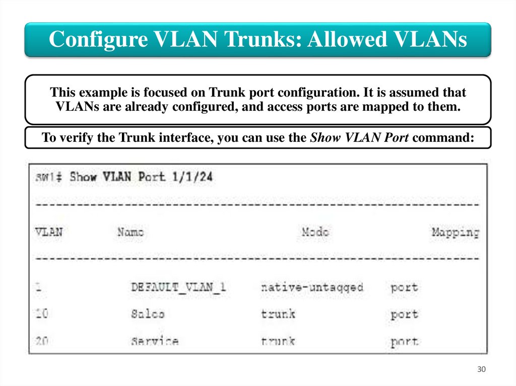
Configure VLAN Trunks: Allowed VLANsThis example is focused on Trunk port configuration. It is assumed that
VLANs are already configured, and access ports are mapped to them.
To verify the Trunk interface, you can use the Show VLAN Port command:
30
31.
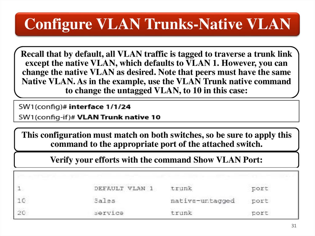
Configure VLAN Trunks-Native VLANRecall that by default, all VLAN traffic is tagged to traverse a trunk link
except the native VLAN, which defaults to VLAN 1. However, you can
change the native VLAN as desired. Note that peers must have the same
Native VLAN. As in the example, use the VLAN Trunk native command
to change the untagged VLAN, to 10 in this case:
This configuration must match on both switches, so be sure to apply this
command to the appropriate port of the attached switch.
Verify your efforts with the command Show VLAN Port:
31
32.
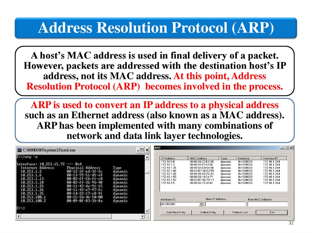
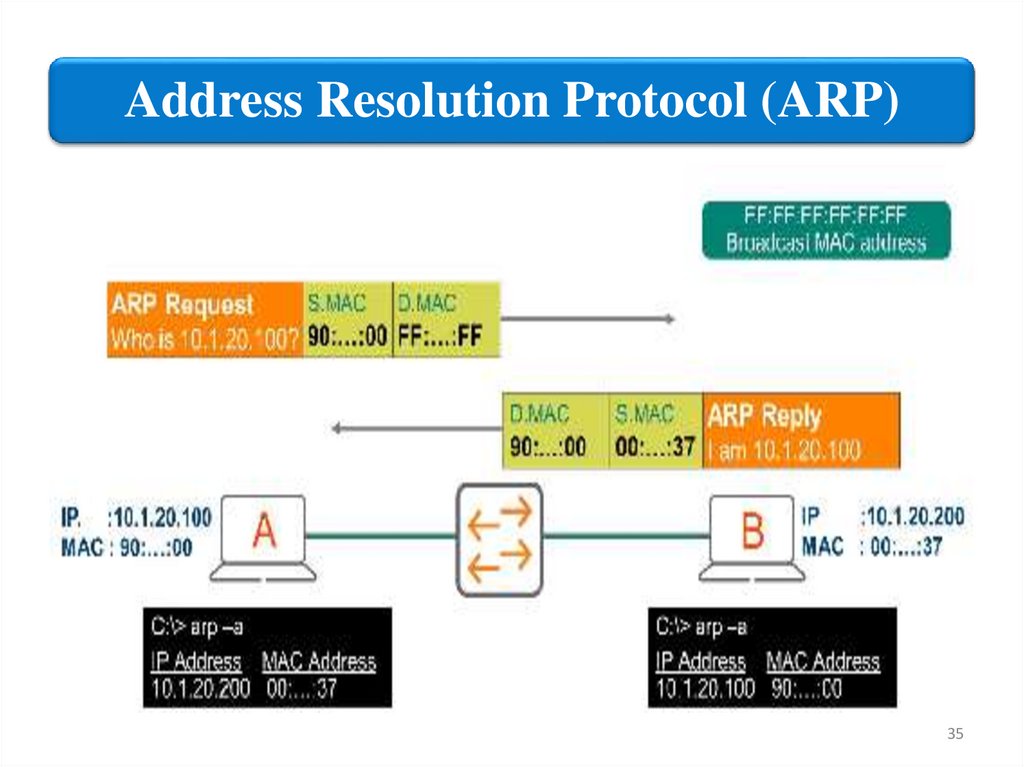
Address Resolution Protocol (ARP)A host’s MAC address is used in final delivery of a packet.
However, packets are addressed with the destination host’s IP
address, not its MAC address. At this point, Address
Resolution Protocol (ARP) becomes involved in the process.
ARP is used to convert an IP address to a physical address
such as an Ethernet address (also known as a MAC address).
ARP has been implemented with many combinations of
network and data link layer technologies.
32
33.
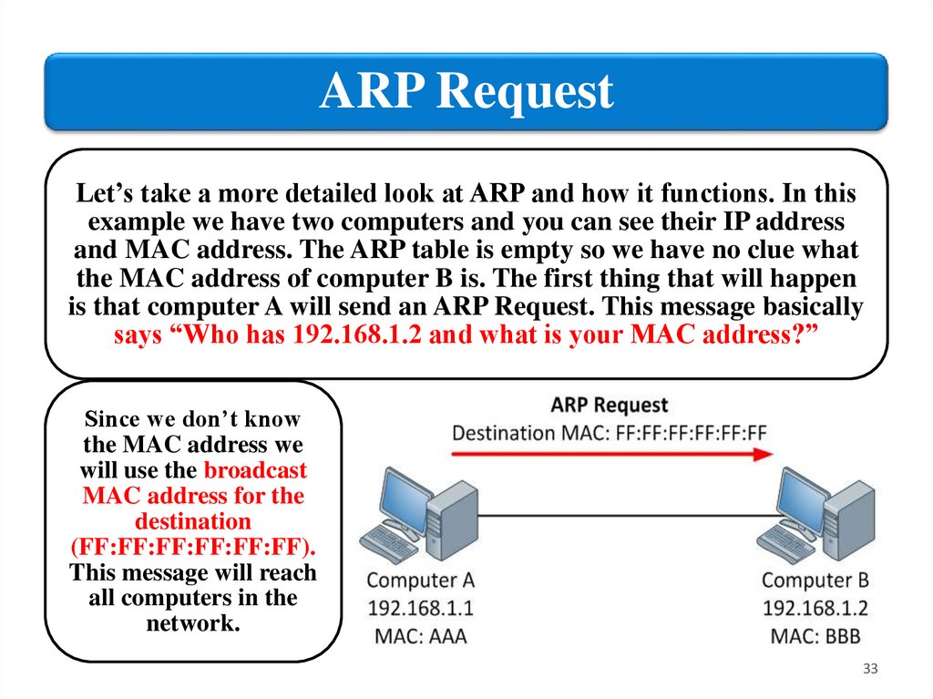
ARP RequestLet’s take a more detailed look at ARP and how it functions. In this
example we have two computers and you can see their IP address
and MAC address. The ARP table is empty so we have no clue what
the MAC address of computer B is. The first thing that will happen
is that computer A will send an ARP Request. This message basically
says “Who has 192.168.1.2 and what is your MAC address?”
Since we don’t know
the MAC address we
will use the broadcast
MAC address for the
destination
(FF:FF:FF:FF:FF:FF).
This message will reach
all computers in the
network.
33
34.
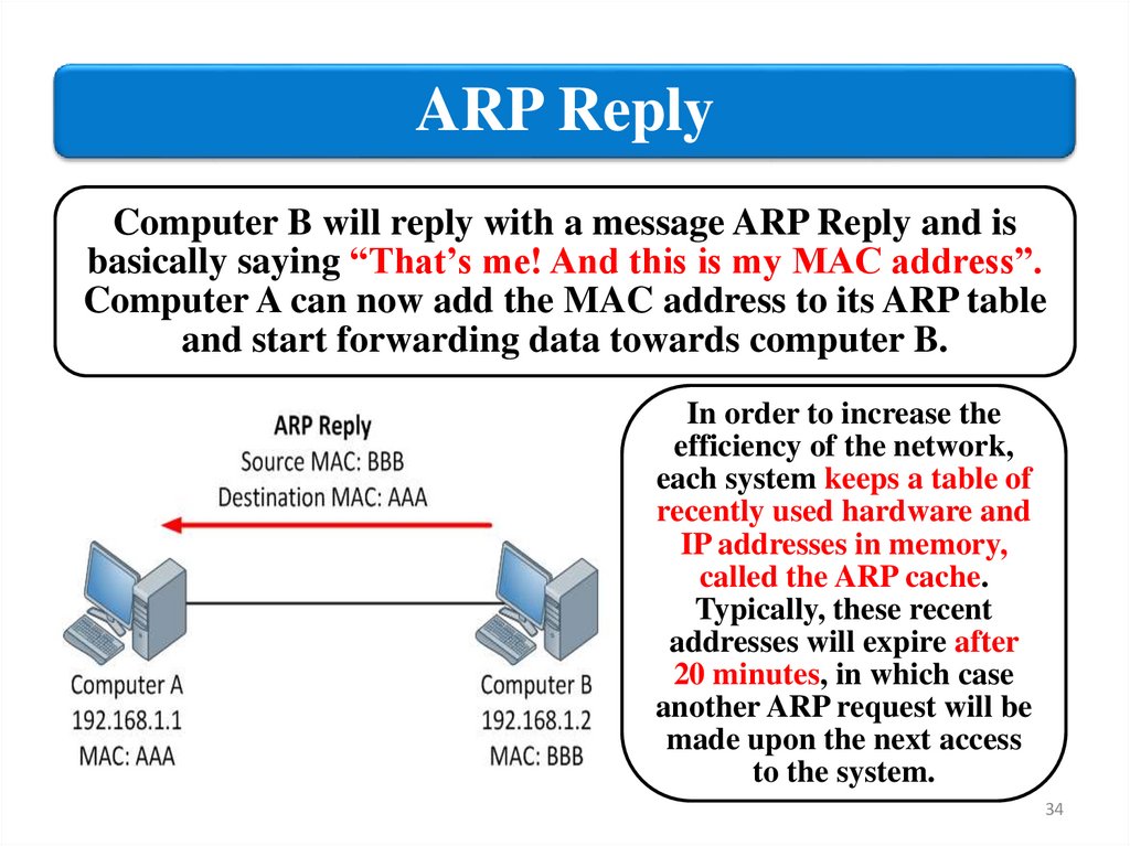
ARP ReplyComputer B will reply with a message ARP Reply and is
basically saying “That’s me! And this is my MAC address”.
Computer A can now add the MAC address to its ARP table
and start forwarding data towards computer B.
In order to increase the
efficiency of the network,
each system keeps a table of
recently used hardware and
IP addresses in memory,
called the ARP cache.
Typically, these recent
addresses will expire after
20 minutes, in which case
another ARP request will be
made upon the next access
to the system.
34
35.
Address Resolution Protocol (ARP)35
36.
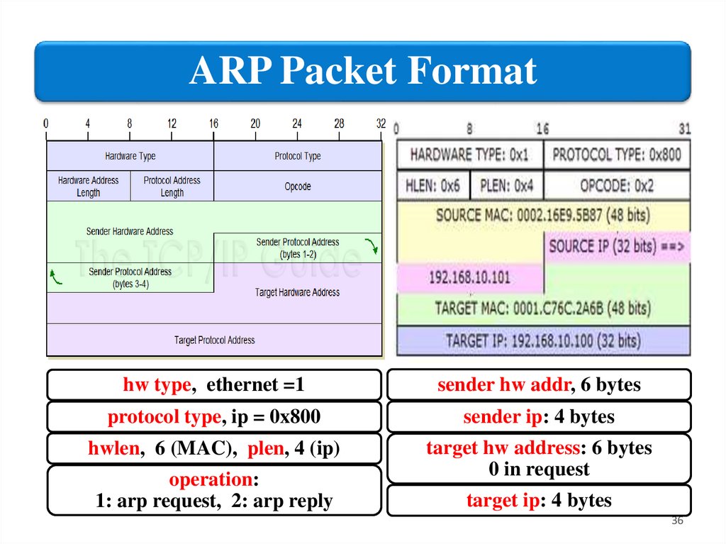
ARP Packet Formathw type, ethernet =1
sender hw addr, 6 bytes
protocol type, ip = 0x800
sender ip: 4 bytes
hwlen, 6 (MAC), plen, 4 (ip)
target hw address: 6 bytes
0 in request
operation:
1: arp request, 2: arp reply
target ip: 4 bytes
36
37.
VLANs2. Configure network
topology
37
38.
Configure a VLANAt this point the Access-1 switch is up and running and ready
for configuration. The next task in your initial network
deployment will be to place wired EMPLOYEES in a custom
VLAN to enable inter-user communication.
38
39.
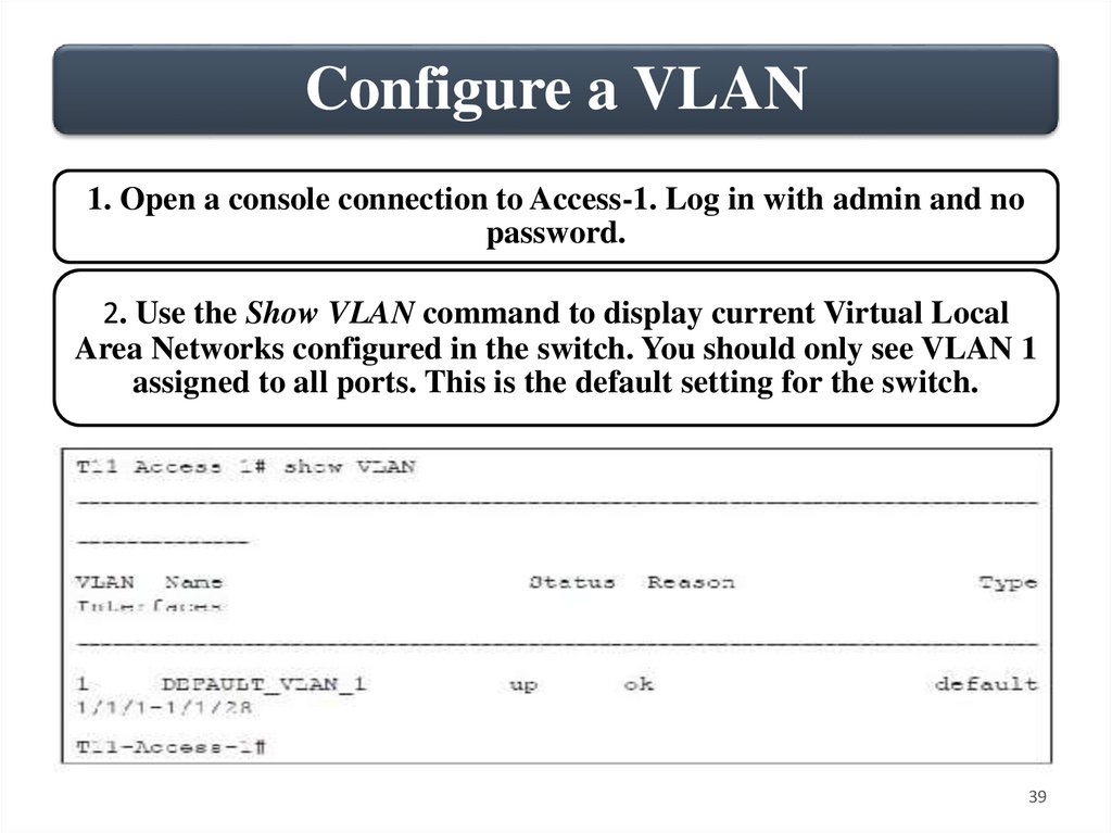
Configure a VLAN1. Open a console connection to Access-1. Log in with admin and no
password.
2. Use the Show VLAN command to display current Virtual Local
Area Networks configured in the switch. You should only see VLAN 1
assigned to all ports. This is the default setting for the switch.
39
40.
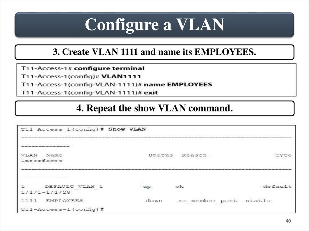
Configure a VLAN3. Create VLAN 1111 and name its EMPLOYEES.
4. Repeat the show VLAN command.
40
41.
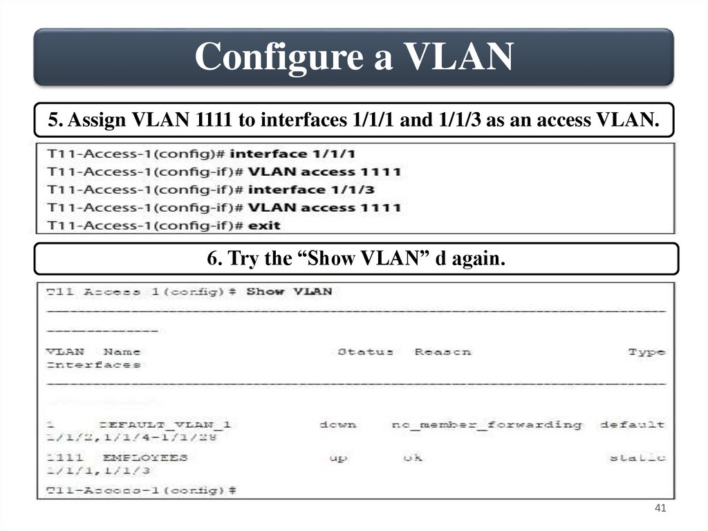
Configure a VLAN5. Assign VLAN 1111 to interfaces 1/1/1 and 1/1/3 as an access VLAN.
6. Try the “Show VLAN” d again.
41
42.
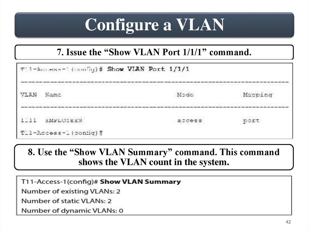
Configure a VLAN7. Issue the “Show VLAN Port 1/1/1” command.
8. Use the “Show VLAN Summary” command. This command
shows the VLAN count in the system.
42
43.
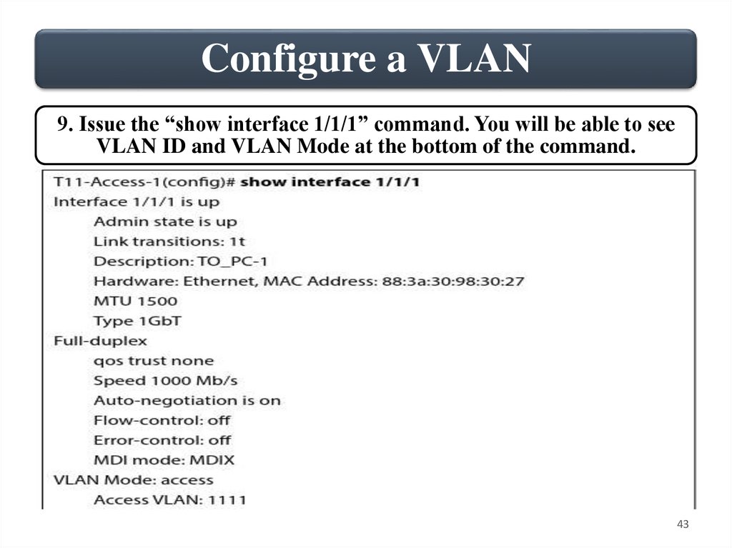
Configure a VLAN9. Issue the “show interface 1/1/1” command. You will be able to see
VLAN ID and VLAN Mode at the bottom of the command.
43
44.
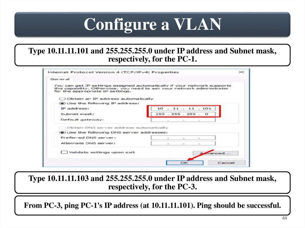
Configure a VLANType 10.11.11.101 and 255.255.255.0 under IP address and Subnet mask,
respectively, for the PC-1.
Type 10.11.11.103 and 255.255.255.0 under IP address and Subnet mask,
respectively, for the PC-3.
From PC-3, ping PC-1's IP address (at 10.11.11.101). Ping should be successful.
44
45.
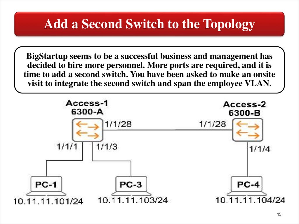
Add a Second Switch to the TopologyBigStartup seems to be a successful business and management has
decided to hire more personnel. More ports are required, and it is
time to add a second switch. You have been asked to make an onsite
visit to integrate the second switch and span the employee VLAN.
45
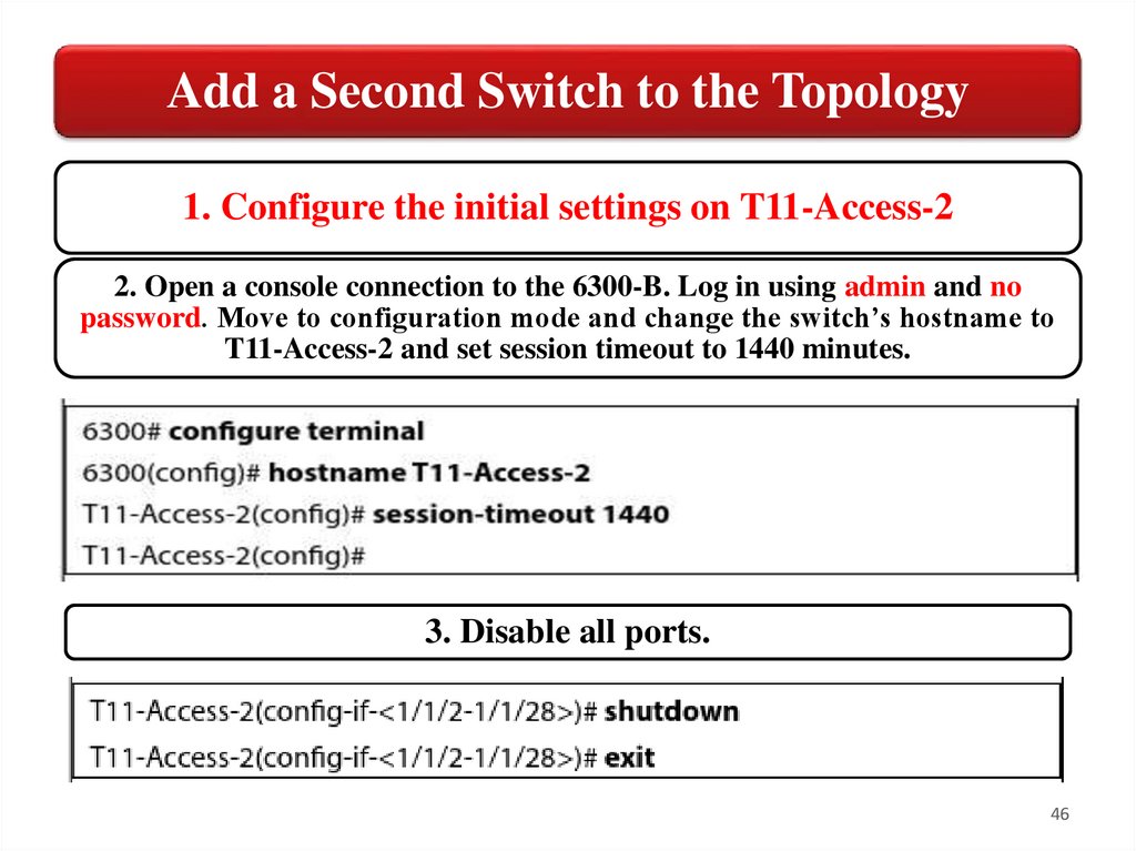
46.
Add a Second Switch to the Topology1. Configure the initial settings on T11-Access-2
2. Open a console connection to the 6300-B. Log in using admin and no
password. Move to configuration mode and change the switch’s hostname to
T11-Access-2 and set session timeout to 1440 minutes.
3. Disable all ports.
46
47.
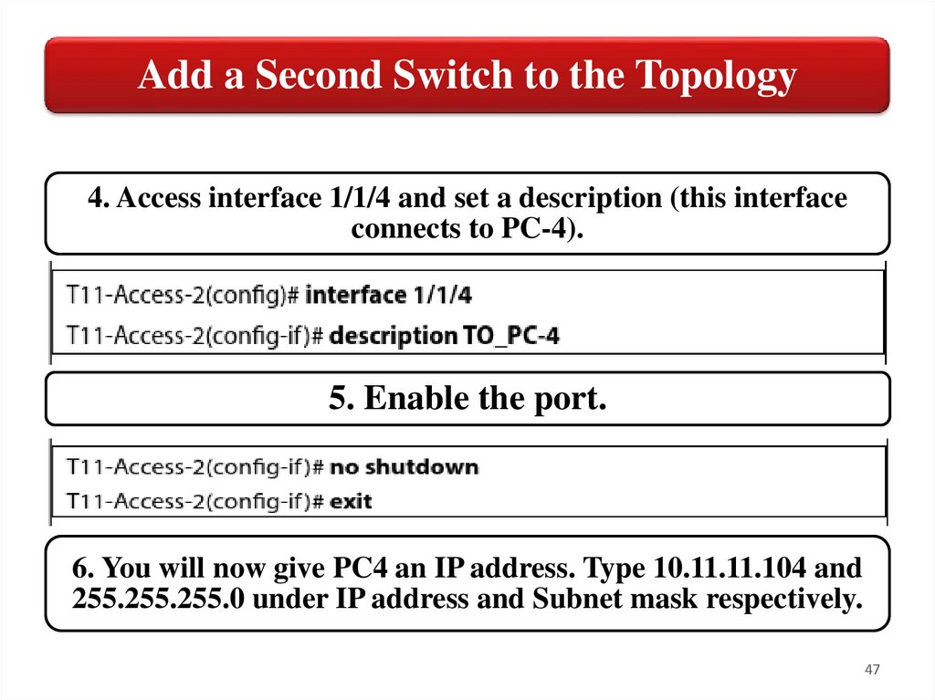
Add a Second Switch to the Topology4. Access interface 1/1/4 and set a description (this interface
connects to PC-4).
5. Enable the port.
6. You will now give PC4 an IP address. Type 10.11.11.104 and
255.255.255.0 under IP address and Subnet mask respectively.
47
48.
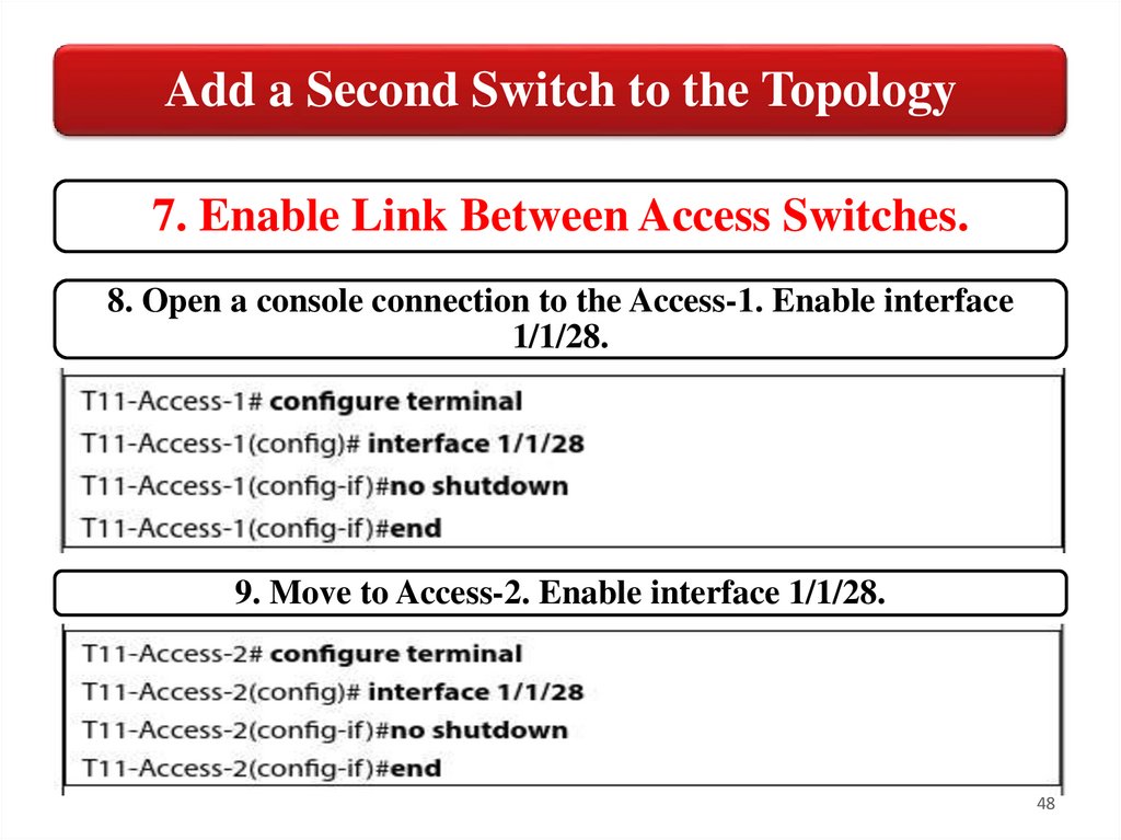
Add a Second Switch to the Topology7. Enable Link Between Access Switches.
8. Open a console connection to the Access-1. Enable interface
1/1/28.
9. Move to Access-2. Enable interface 1/1/28.
48
49.
Add a Second Switch to the Topology10. Set descriptions on both switches’ interface 1/1/28.
11. Move back to PC-4 and ping PC-1's IP address (10.11.11.101).
Destination port unreachable.
49
50.
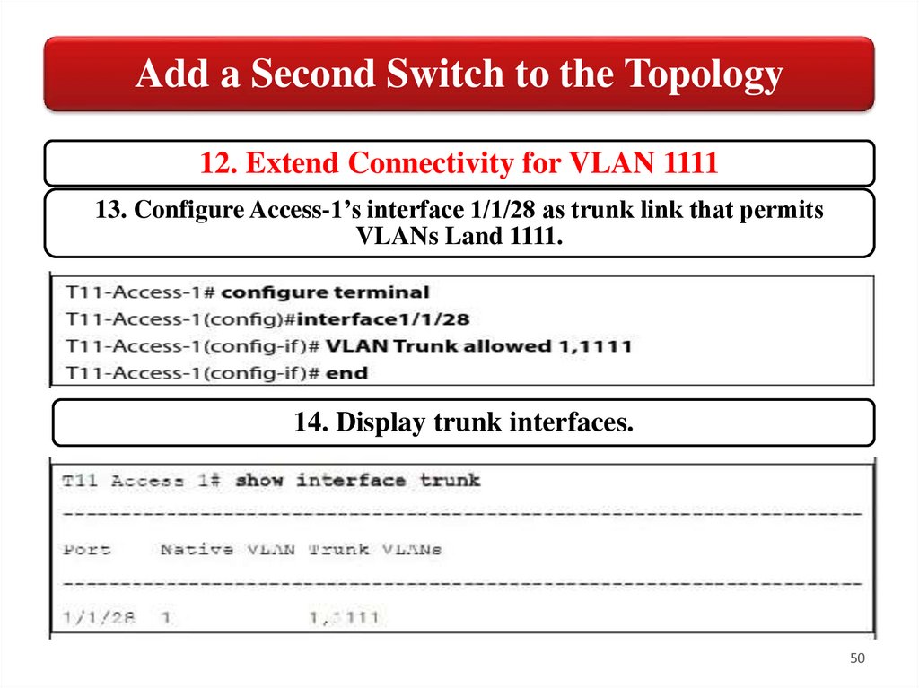
Add a Second Switch to the Topology12. Extend Connectivity for VLAN 1111
13. Configure Access-1’s interface 1/1/28 as trunk link that permits
VLANs Land 1111.
14. Display trunk interfaces.
50
51.
Add a Second Switch to the Topology15. Move to Access-2. Create VLAN 1111 and name its EMPLOYEES.
16. Configure Access-2’s interface 1/1/28 as trunk link that permit VLANs 1 and 1111.
17. Last configure interface 1/1/4 as access port in VLAN 1111.
51
52.
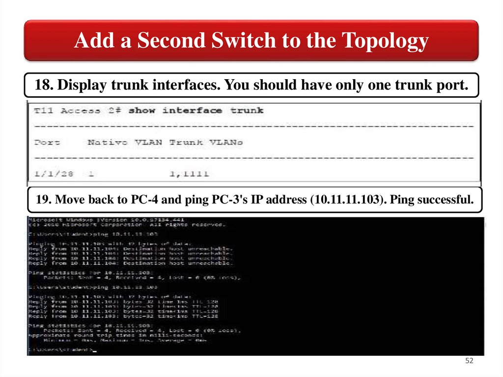
Add a Second Switch to the Topology18. Display trunk interfaces. You should have only one trunk port.
19. Move back to PC-4 and ping PC-3's IP address (10.11.11.103). Ping successful.
52
53.
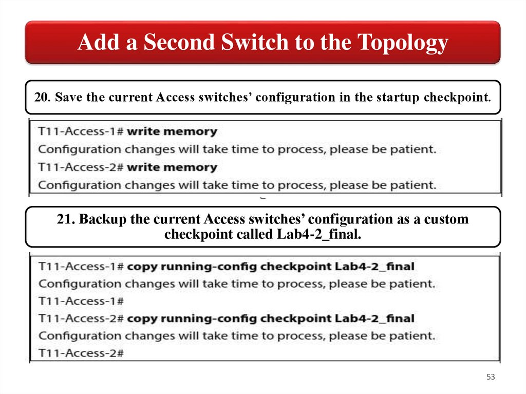
Add a Second Switch to the Topology20. Save the current Access switches’ configuration in the startup checkpoint.
21. Backup the current Access switches’ configuration as a custom
checkpoint called Lab4-2_final.
53
54.
Add a Core Switch to the TopologyAfter few months in business, BiaStartup seems to have a promising
forecast Sales are growing and more employees are being hired. The
company is urgently investigating and renting the West Wing of the
floor. Management is considering the implications of expansion and what
effect it will have on the network.
They have approached you for advice and you have recommended the
insertion of a Core switch, following a two-tier design that can assure
future growth with no complexity (instead of a daisy chain-based
topology). You suggest an 8325 AOS-CX switch, which assures a
consistent OS across the board, high port density, unprecedented
throughput, and no blocking switching. While management agrees with
your recommendation and can budget for the new gear, it turns out that
the building owner, Cheap4Rent, also offers some degree of network
services for all their tenants.
54
55.
Add a Core Switch to the TopologyCheap4Rent offers to include the same 8325 AOS-CX switch in the lease.
This permits the company to save capital and invest in other assets such
as servers, IP telephony, video surveillance, etc.
BigStartup is the first tenant to be offered the Core Switching service
and to facilitate the integration, they are giving you limited network
operations access over SSH and will allow you to use the default VRF for
now.
After completing this, you will be able to:
• Deploy a Core Switch to the topology
• Configure uplinks as trunk ports by enabling 802.1Q
• Add anew VLAN for another users’ type
• Enable DHCP server on Access-1
55
56.
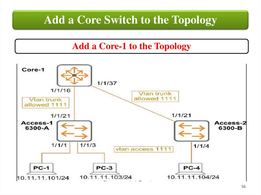
Add a Core Switch to the TopologyAdd a Core-1 to the Topology
56
57.
Add a Core Switch to the TopologyIn this task, you will change the switching topology and
enable ports on the Access switches that have been
connected to the 8325 AOS-CX Core Switch that resides
in the Building's MDF. You will also configure the core
switch side of the links and validate the topology.
Even though 8300 platforms come with disabled routed
ports by default, CCheap4Rent has turned the Core ports
on and made them switch interfaces. They have provided
Ethernet wire drops for establishing Layer-1 connectivity
between the Core and Access switches.
57
58.
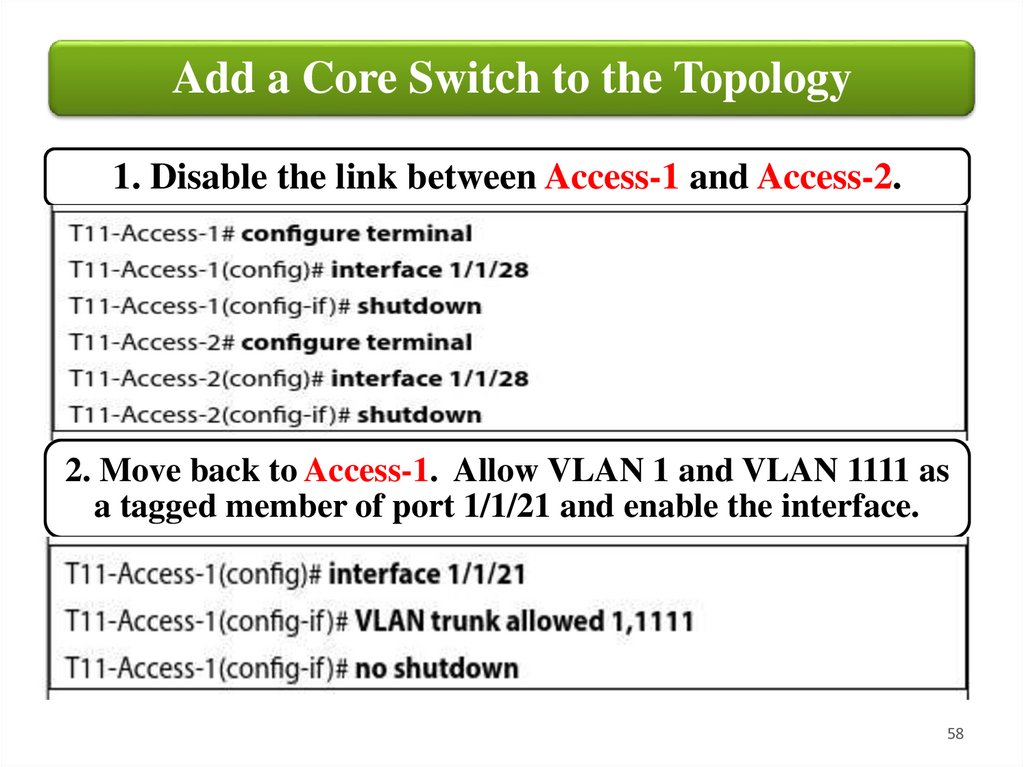
Add a Core Switch to the Topology1. Disable the link between Access-1 and Access-2.
2. Move back to Access-1. Allow VLAN 1 and VLAN 1111 as
a tagged member of port 1/1/21 and enable the interface.
58
59.
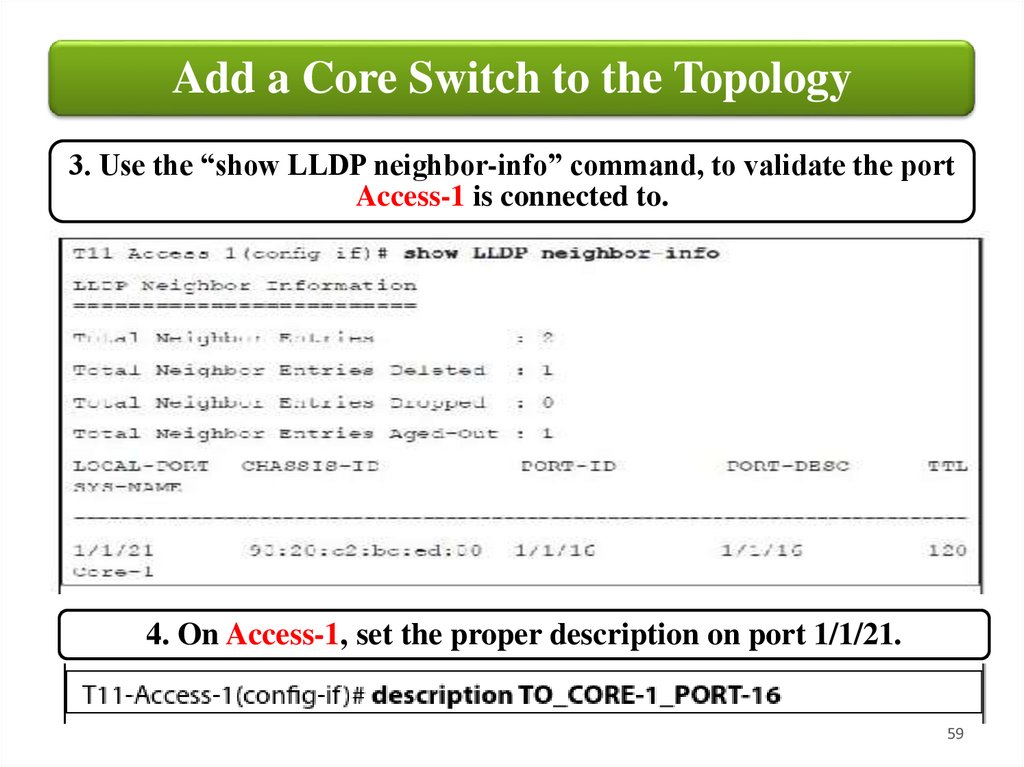
Add a Core Switch to the Topology3. Use the “show LLDP neighbor-info” command, to validate the port
Access-1 is connected to.
4. On Access-1, set the proper description on port 1/1/21.
59
60.
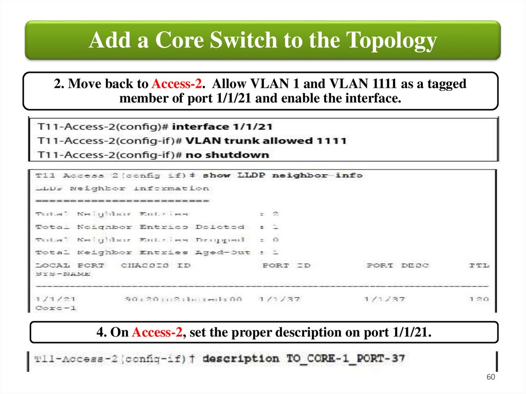
Add a Core Switch to the Topology2. Move back to Access-2. Allow VLAN 1 and VLAN 1111 as a tagged
member of port 1/1/21 and enable the interface.
4. On Access-2, set the proper description on port 1/1/21.
60
61.
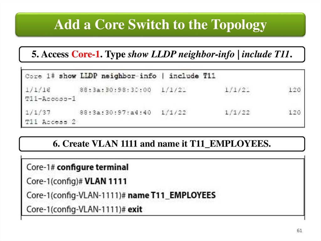
Add a Core Switch to the Topology5. Access Core-1. Type show LLDP neighbor-info | include T11.
6. Create VLAN 1111 and name it T11_EMPLOYEES.
61
62.
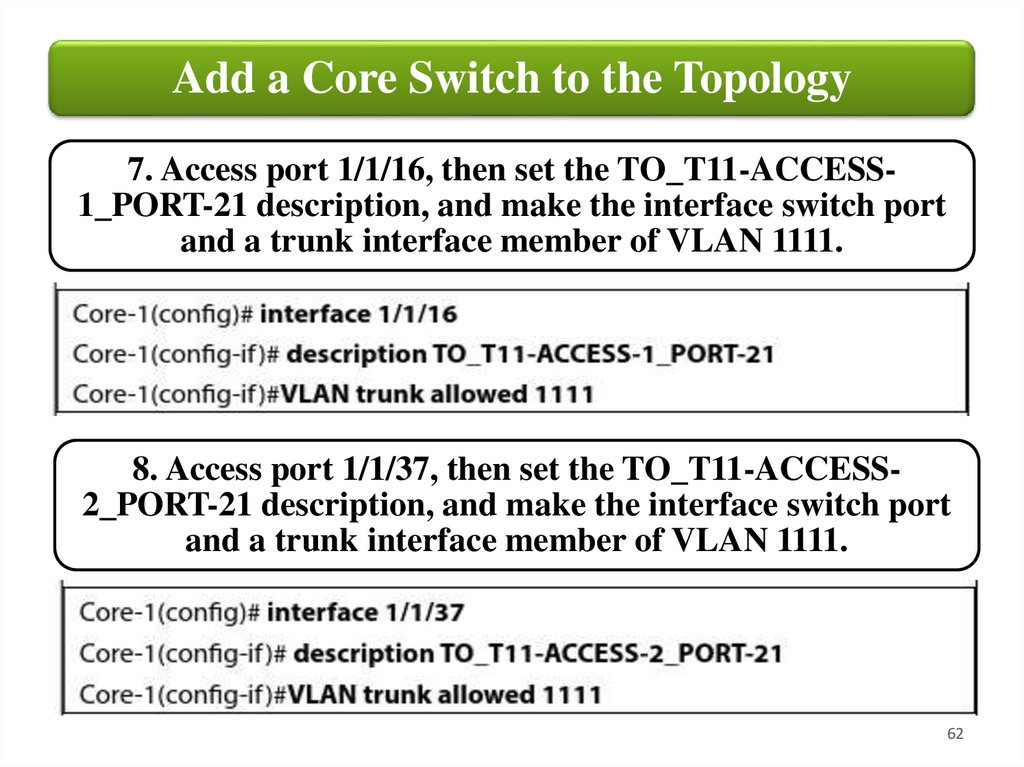
Add a Core Switch to the Topology7. Access port 1/1/16, then set the TO_T11-ACCESS1_PORT-21 description, and make the interface switch port
and a trunk interface member of VLAN 1111.
8. Access port 1/1/37, then set the TO_T11-ACCESS2_PORT-21 description, and make the interface switch port
and a trunk interface member of VLAN 1111.
62
63.
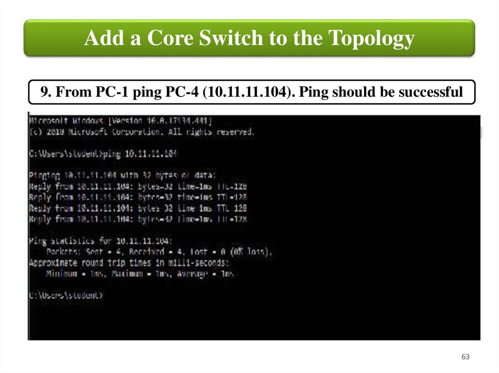
Add a Core Switch to the Topology9. From PC-1 ping PC-4 (10.11.11.104). Ping should be successful
63
64.
Add a Core Switch to the TopologyAdding a Second VLAN
After more hiring, BigStartup is now interested in improving
privacy and B traffic separation between regular employees
and managers. They are asking you if there is any way you can
achieve that with networking devices they already have. You
can improve privacy and traffic separation by adding VLAN.
The next steps will be focused on creating VLAN 1112 for
managers across all switches and moving PC-1 and PC-4 into
that broadcast domain.
64
65.
Add a Core Switch to the Topology65
66.
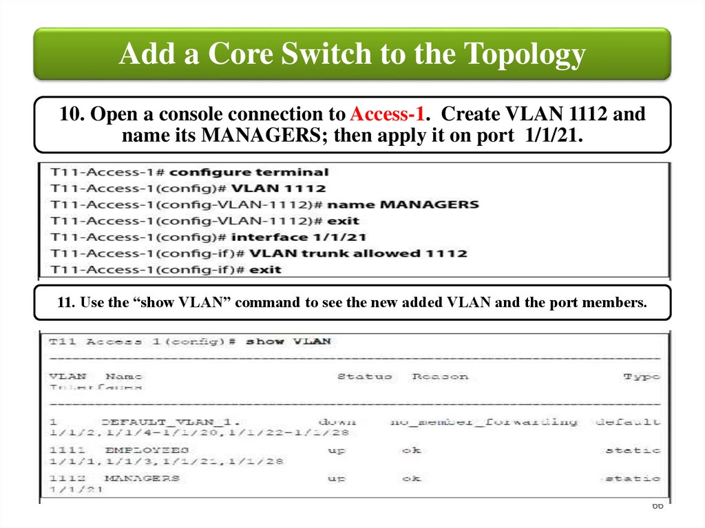
Add a Core Switch to the Topology10. Open a console connection to Access-1. Create VLAN 1112 and
name its MANAGERS; then apply it on port 1/1/21.
11. Use the “show VLAN” command to see the new added VLAN and the port members.
66
67.
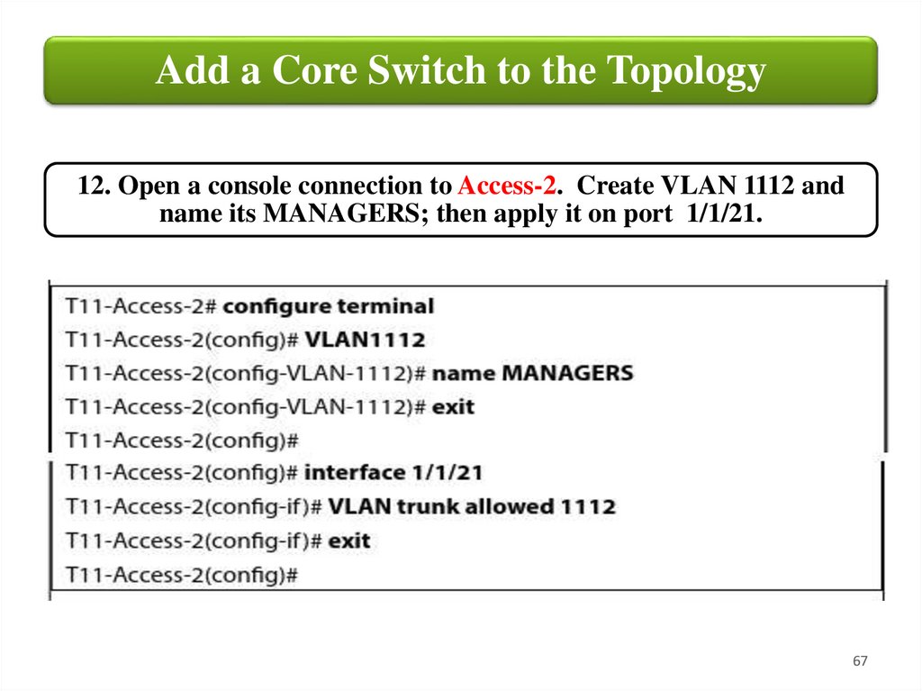
Add a Core Switch to the Topology12. Open a console connection to Access-2. Create VLAN 1112 and
name its MANAGERS; then apply it on port 1/1/21.
67
68.
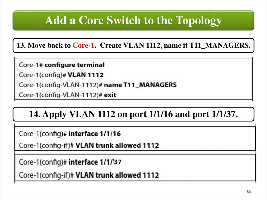
Add a Core Switch to the Topology13. Move back to Core-1. Create VLAN 1112, name it T11_MANAGERS.
14. Apply VLAN 1112 on port 1/1/16 and port 1/1/37.
68
69.
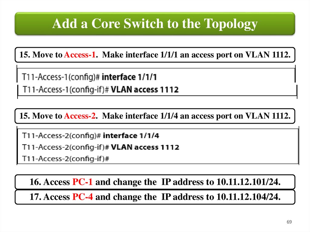
Add a Core Switch to the Topology15. Move to Access-1. Make interface 1/1/1 an access port on VLAN 1112.
15. Move to Access-2. Make interface 1/1/4 an access port on VLAN 1112.
16. Access PC-1 and change the IP address to 10.11.12.101/24.
17. Access PC-4 and change the IP address to 10.11.12.104/24.
69
70.
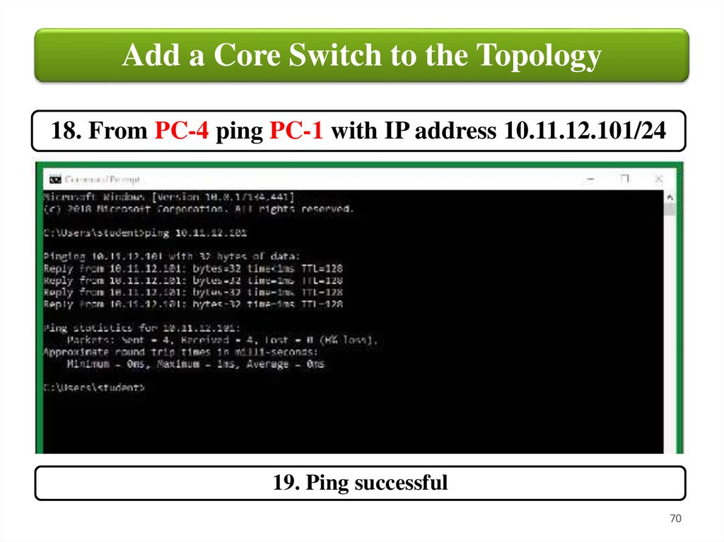
Add a Core Switch to the Topology18. From PC-4 ping PC-1 with IP address 10.11.12.101/24
19. Ping successful
70
71.
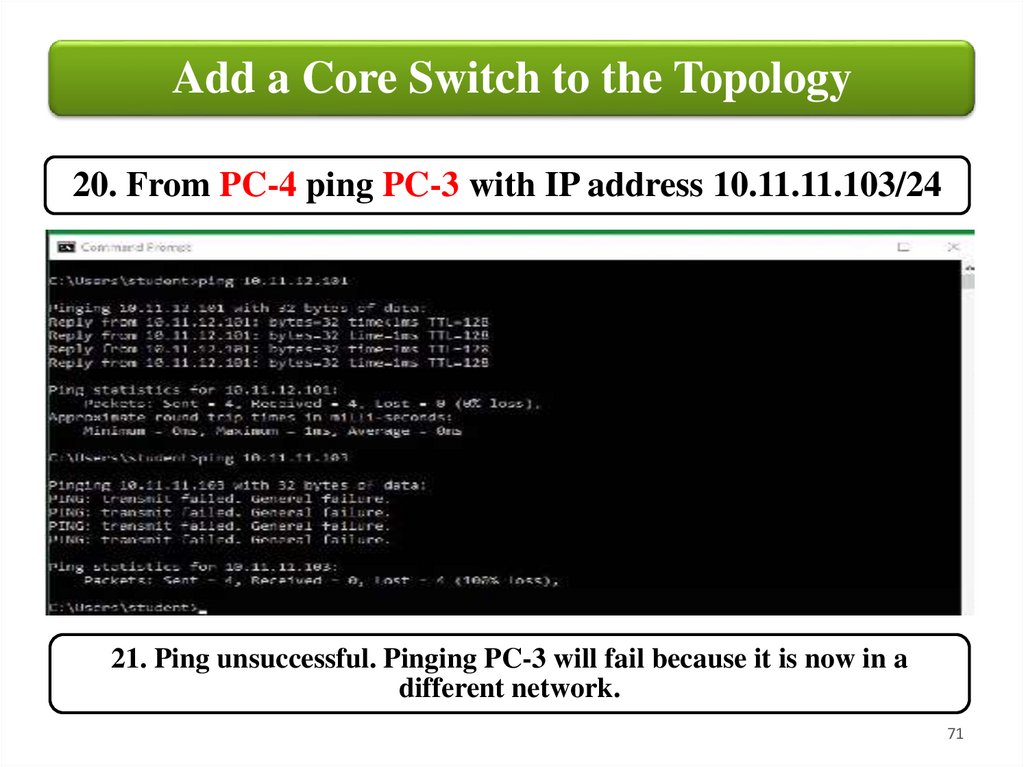
Add a Core Switch to the Topology20. From PC-4 ping PC-3 with IP address 10.11.11.103/24
21. Ping unsuccessful. Pinging PC-3 will fail because it is now in a
different network.
71
72.
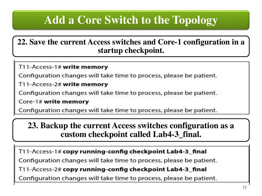
Add a Core Switch to the Topology22. Save the current Access switches and Core-1 configuration in a
startup checkpoint.
23. Backup the current Access switches configuration as a
custom checkpoint called Lab4-3_final.
72