


 Интернет
 Электроника
Похожие презентации:


")


Hardware Fundamentals. Lecture 2
1.
Lecture 2Hardware
Fundamentals
1
2.
Objectives1. Identify the purpose and use of
network hardware.
2. Describe common switch types.
3. Configure custom VLANs.
4. Identify switch management
interfaces.
2
3.
HardwareFundamentals
1. Identify the purpose and use of
common network hardware
3
4.
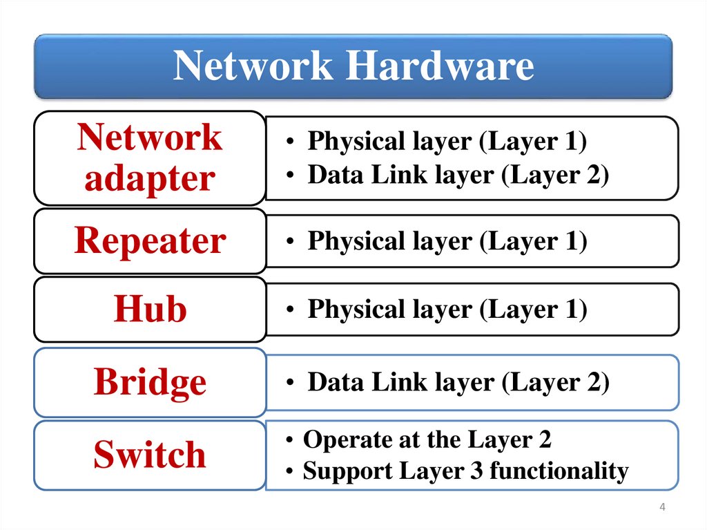
Network HardwareNetwork
adapter
• Physical layer (Layer 1)
• Data Link layer (Layer 2)
Repeater
• Physical layer (Layer 1)
Hub
• Physical layer (Layer 1)
Bridge
• Data Link layer (Layer 2)
Switch
• Operate at the Layer 2
• Support Layer 3 functionality
4
5.
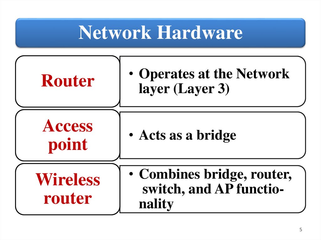
Network HardwareRouter
• Operates at the Network
layer (Layer 3)
Access
point
• Acts as a bridge
Wireless
router
• Combines bridge, router,
switch, and AP functionality
5
6.
Network AdapterA network adapter (called a network interface
controller or NIC) is a hardware card installed in a
computer so it can communicate on a network. The
network adapter transmits and receives data onto
the network cable.
The NIC is both a Physical layer and Data link
layer device, as it provides physical access to a
networking medium and provides a low-level
addressing system through the use of MAC
addresses that are uniquely assigned to network
interfaces.
6
7.
Types of Network AdapterThere are
two basic
types of
networks:
wired and
wireless:
• Wired Network
Adapter
• Wireless Network
Adapter
• Network USB
Adapter
7
8.
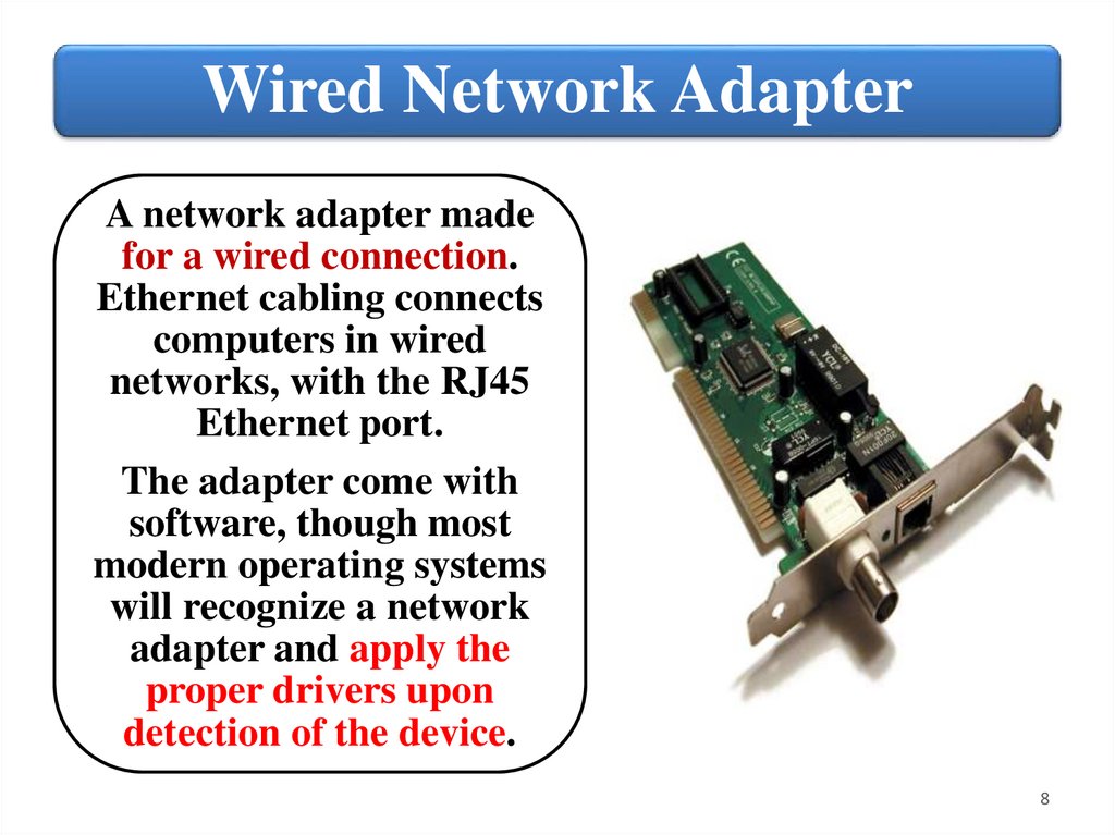
Wired Network AdapterA network adapter made
for a wired connection.
Ethernet cabling connects
computers in wired
networks, with the RJ45
Ethernet port.
The adapter come with
software, though most
modern operating systems
will recognize a network
adapter and apply the
proper drivers upon
detection of the device.
8
9.
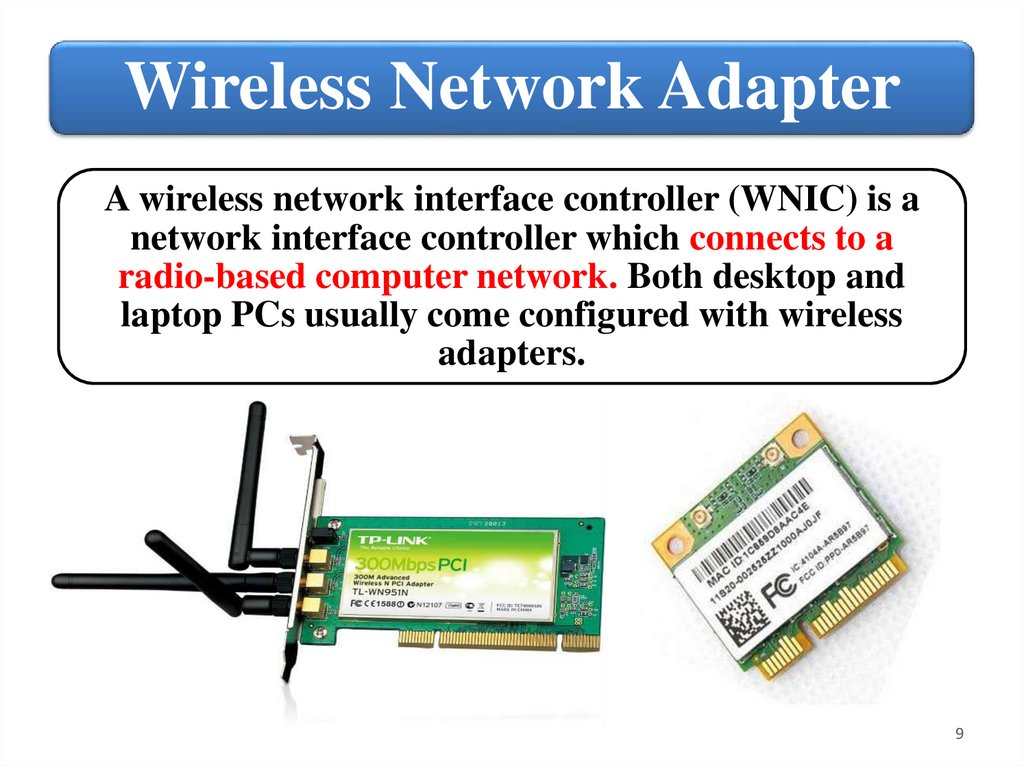
Wireless Network AdapterA wireless network interface controller (WNIC) is a
network interface controller which connects to a
radio-based computer network. Both desktop and
laptop PCs usually come configured with wireless
adapters.
9
10.
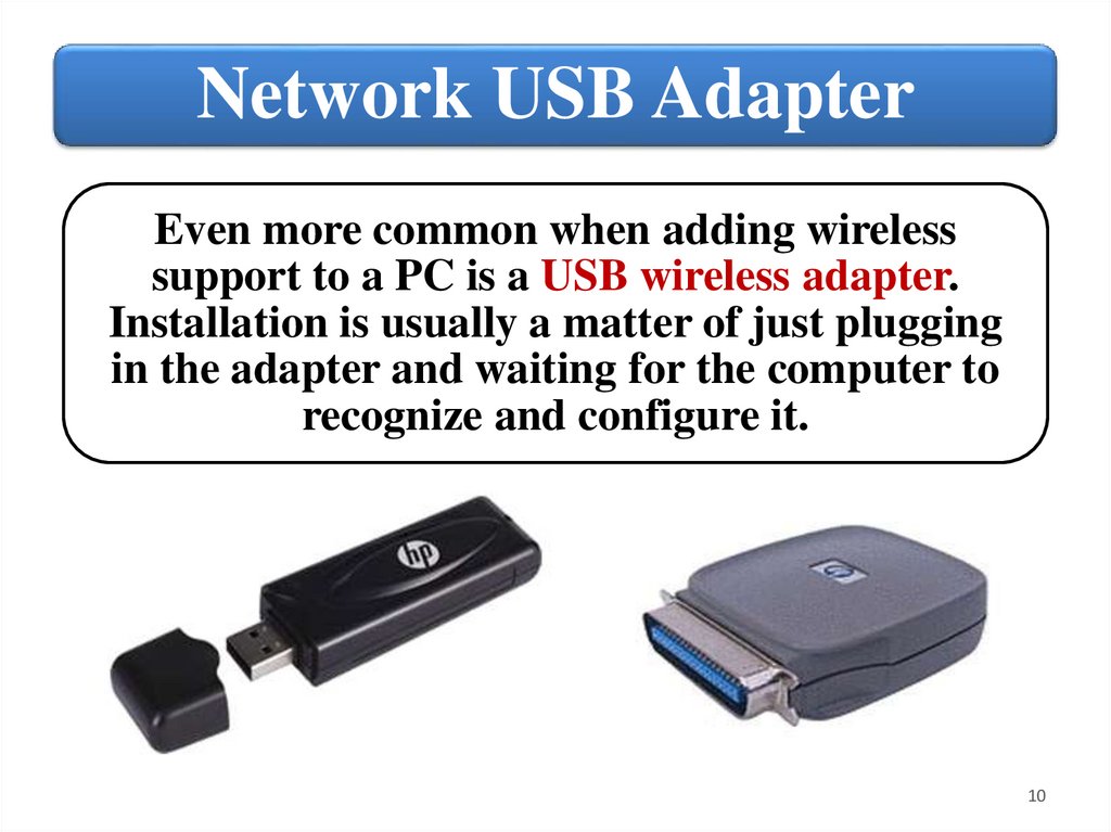
Network USB AdapterEven more common when adding wireless
support to a PC is a USB wireless adapter.
Installation is usually a matter of just plugging
in the adapter and waiting for the computer to
recognize and configure it.
10
11.
Adapter MAC addressWhether it is built‐in or added on, a
network adapter performs the same
functions for a PC or other network device.
The network adapter will be coded with a
unique Media Access Control (MAC)
address used to identify the device on the
network and will have a means of
connecting to the network transmission
media.
11
12.
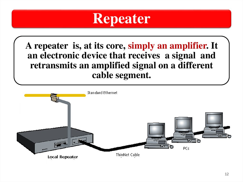
RepeaterA repeater is, at its core, simply an amplifier. It
an electronic device that receives a signal and
retransmits an amplified signal on a different
cable segment.
12
13.
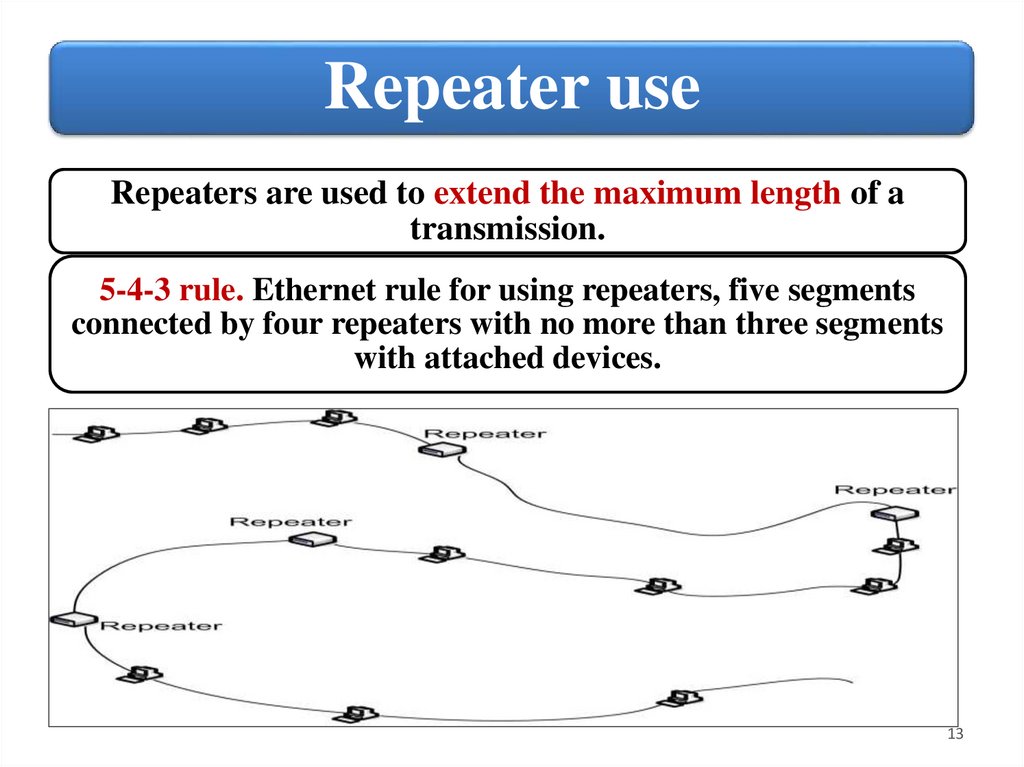
Repeater useRepeaters are used to extend the maximum length of a
transmission.
5-4-3 rule. Ethernet rule for using repeaters, five segments
connected by four repeaters with no more than three segments
with attached devices.
13
14.
HubHub is a device for connecting multiple Ethernet
devices together and making them act as a single
network segment.
14
15.
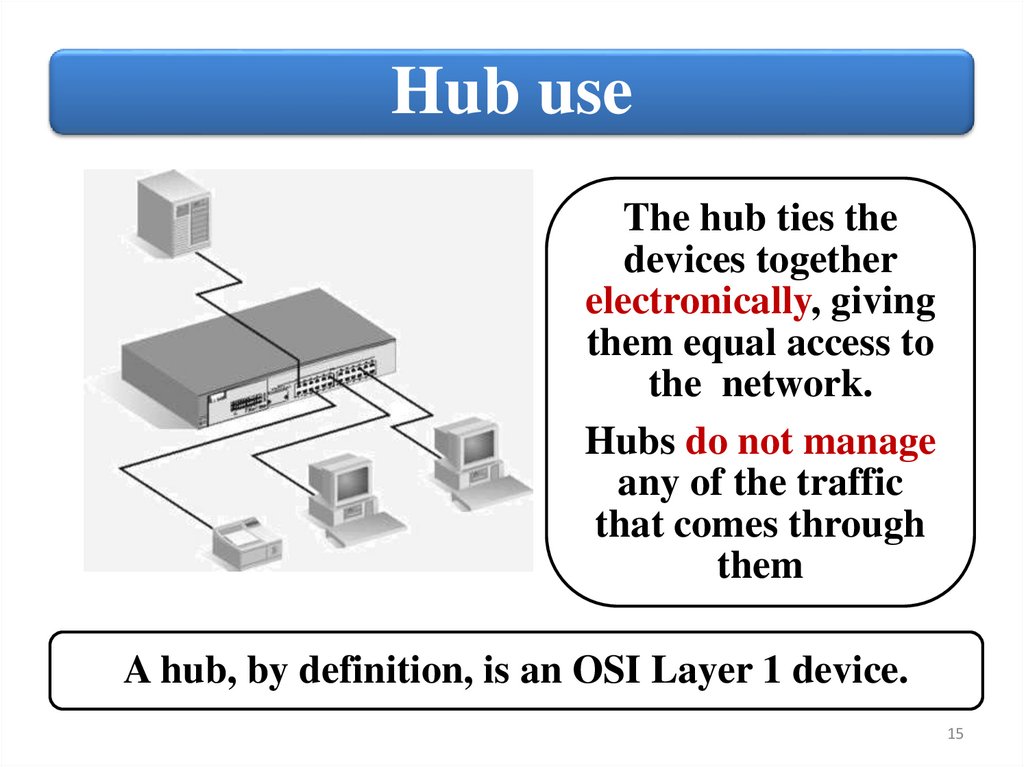
Hub useThe hub ties the
devices together
electronically, giving
them equal access to
the network.
Hubs do not manage
any of the traffic
that comes through
them
A hub, by definition, is an OSI Layer 1 device.
15
16.
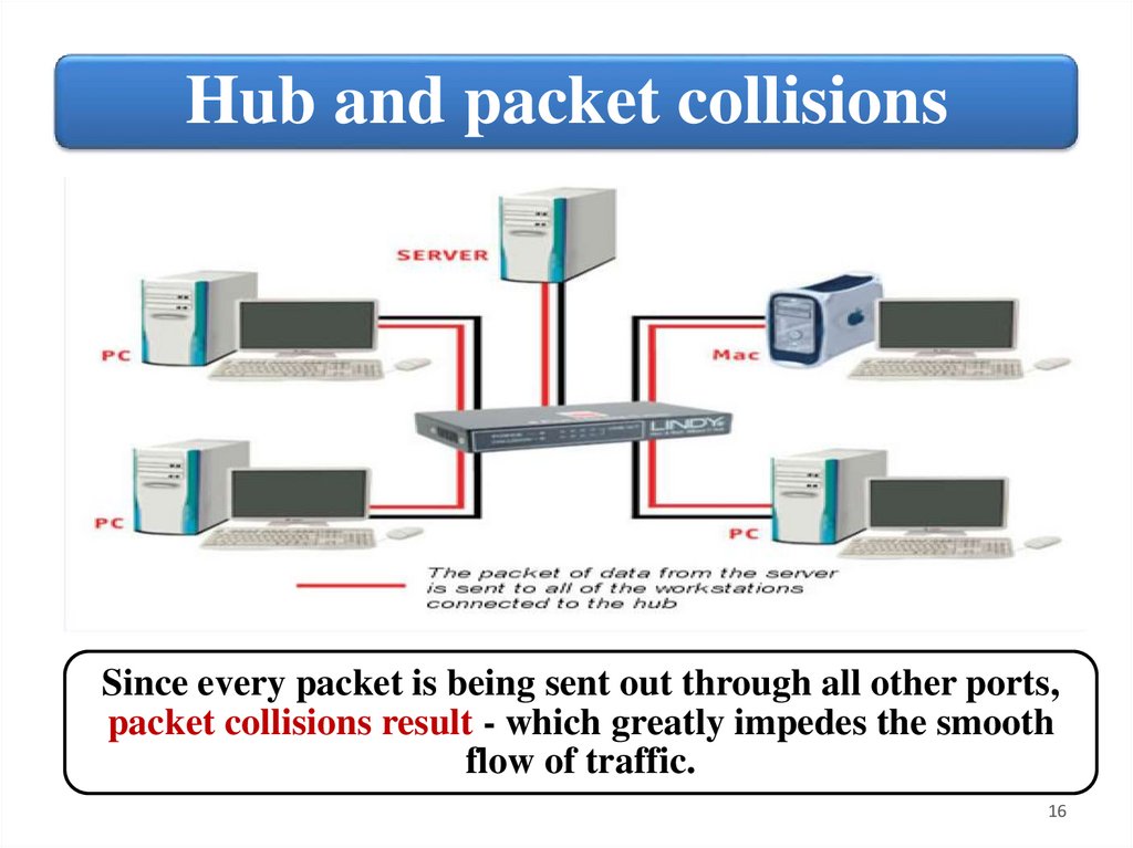
Hub and packet collisionsSince every packet is being sent out through all other ports,
packet collisions result - which greatly impedes the smooth
flow of traffic.
16
17.
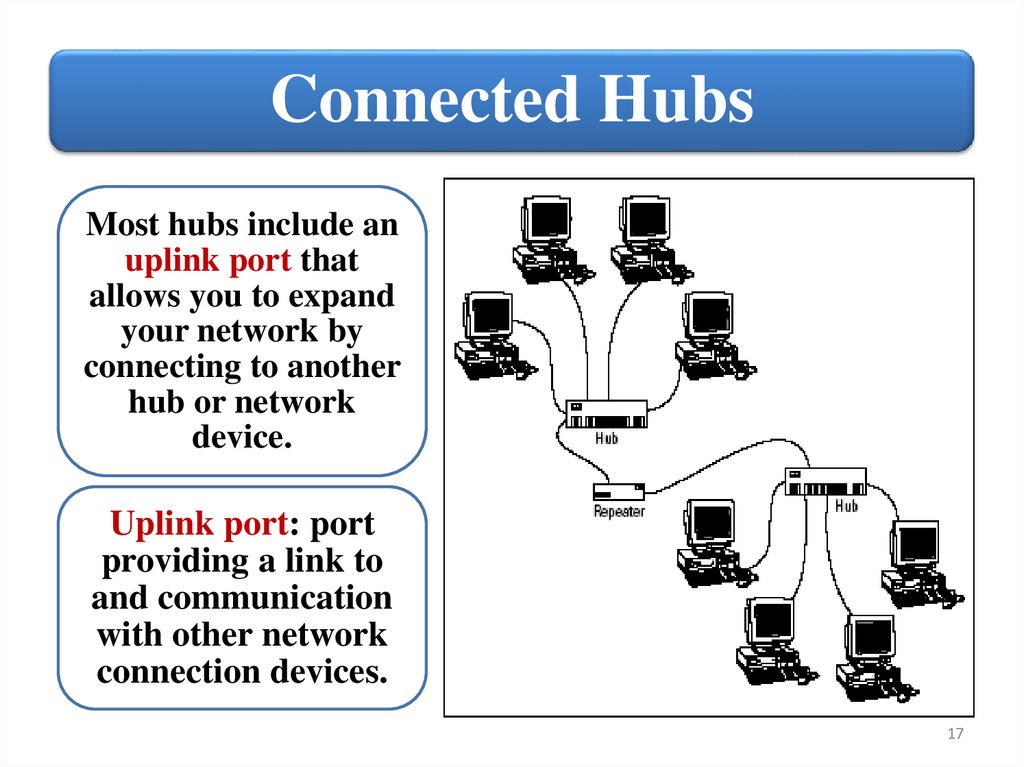
Connected HubsMost hubs include an
uplink port that
allows you to expand
your network by
connecting to another
hub or network
device.
Uplink port: port
providing a link to
and communication
with other network
connection devices.
17
18.
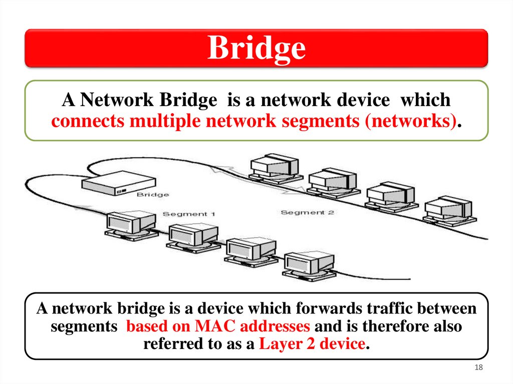
BridgeA Network Bridge is a network device which
connects multiple network segments (networks).
A network bridge is a device which forwards traffic between
segments based on MAC addresses and is therefore also
referred to as a Layer 2 device.
18
19.
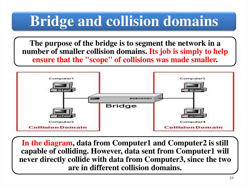
Bridge and collision domainsThe purpose of the bridge is to segment the network in a
number of smaller collision domains. Its job is simply to help
ensure that the "scope" of collisions was made smaller.
In the diagram, data from Computer1 and Computer2 is still
capable of colliding. However, data sent from Computer1 will
never directly collide with data from Computer3, since the two
are in different collision domains.
19
20.
Bridge and media typesA Network Bridge is a hardware, that
connects two or more networks – maybe one
a wired one and the other a wireless one – so
that they can communicate with each other.
The network bridge can create connections
between different media types of network.
Network Bridge automates the configuration
that is required in order to forward
information from one type of media to
another.
20
21.
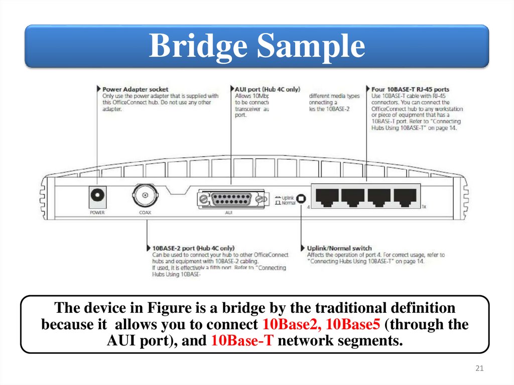
Bridge SampleThe device in Figure is a bridge by the traditional definition
because it allows you to connect 10Base2, 10Base5 (through the
AUI port), and 10Base‐T network segments.
21
22.
SwitchA switch is a computer
networking device that
connects devices together on
a computer network, by
using packet switching to
receive, process and forward
data to the destination
device.
• Switch provide:
• Connect network
devices
• Network segmentation
(VLANs)
• Remote management
• Communication
security
22
23.
Connect network devicesA switch acts like a multiport bridge. It can buffer traffic
between ports using a technology known as store and forward,
which eliminates collisions.
A switch maintains a table that tracks MAC addresses. It forwards
traffic based on the MAC address of the destination address.
23
24.
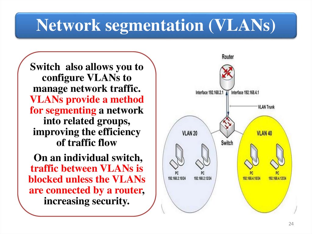
Network segmentation (VLANs)Switch also allows you to
configure VLANs to
manage network traffic.
VLANs provide a method
for segmenting a network
into related groups,
improving the efficiency
of traffic flow
On an individual switch,
traffic between VLANs is
blocked unless the VLANs
are connected by a router,
increasing security.
24
25.
Switch and remote managementMost switches are designed to support remote
management. This means that you can
remotely manage configurable parameters
and also update switch software, back up
configuration information, manage port
activity, and so forth.
Many switches also provide a high level of
communication security by encrypting
communication with connected devices.
25
26.
RouterA router is a networking device that forwards data packets
between computer networks. A router is connected to two or
more data lines from different networks.
When a data packet comes in one of the lines, the router reads the
address information in the packet to determine its ultimate
destination. Then, using information in its routing table or routing
policy, it directs the packet to the next network on its journey.
26
27.
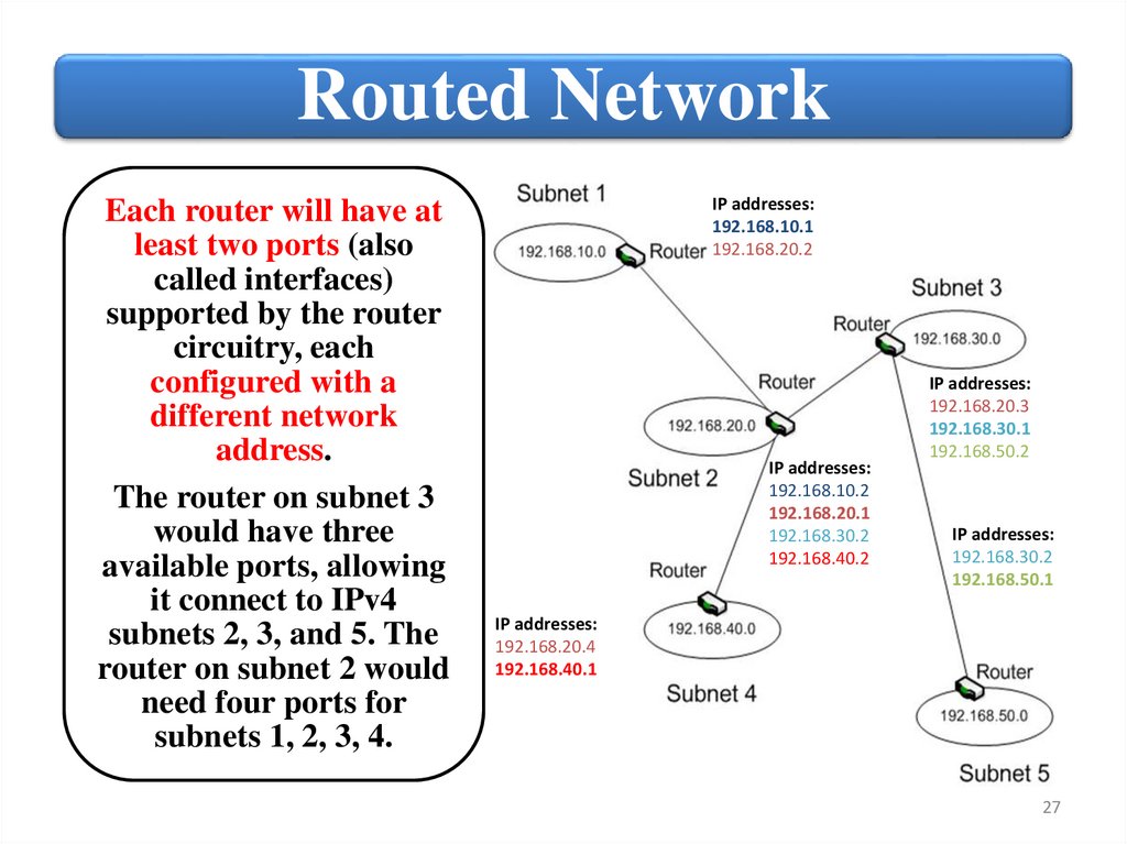
Routed NetworkEach router will have at
least two ports (also
called interfaces)
supported by the router
circuitry, each
configured with a
different network
address.
The router on subnet 3
would have three
available ports, allowing
it connect to IPv4
subnets 2, 3, and 5. The
router on subnet 2 would
need four ports for
subnets 1, 2, 3, 4.
IP addresses:
192.168.10.1
192.168.20.2
IP addresses:
192.168.10.2
192.168.20.1
192.168.30.2
192.168.40.2
IP addresses:
192.168.20.3
192.168.30.1
192.168.50.2
IP addresses:
192.168.30.2
192.168.50.1
IP addresses:
192.168.20.4
192.168.40.1
27
28.
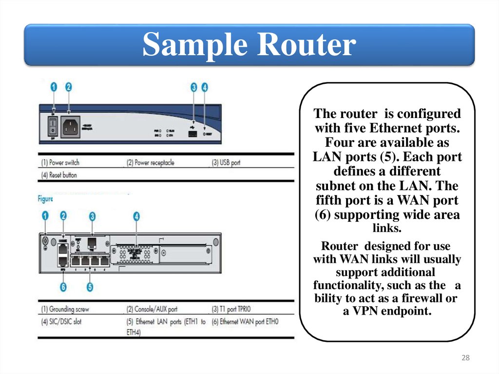
Sample RouterThe router is configured
with five Ethernet ports.
Four are available as
LAN ports (5). Each port
defines a different
subnet on the LAN. The
fifth port is a WAN port
(6) supporting wide area
links.
Router designed for use
with WAN links will usually
support additional
functionality, such as the a
bility to act as a firewall or
a VPN endpoint.
28
29.
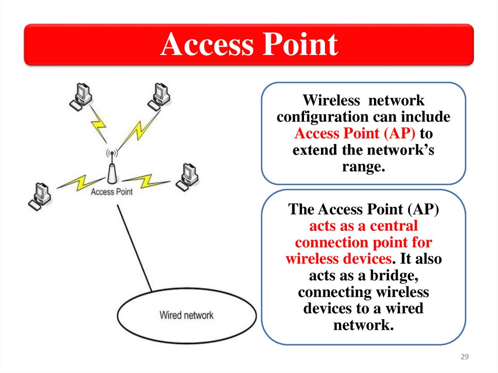
Access PointWireless network
configuration can include
Access Point (AP) to
extend the network’s
range.
The Access Point (AP)
acts as a central
connection point for
wireless devices. It also
acts as a bridge,
connecting wireless
devices to a wired
network.
29
30.
MSM460 Front ViewThe Access Point
will have one or
more internal
radios. Each radio
can be configured
separately, and
usually you can
disable a radio if it
is not needed.
Most HP APs support both a web‐based
management tool and a CLI through which you can
configure the AP, including its radios.
30
31.
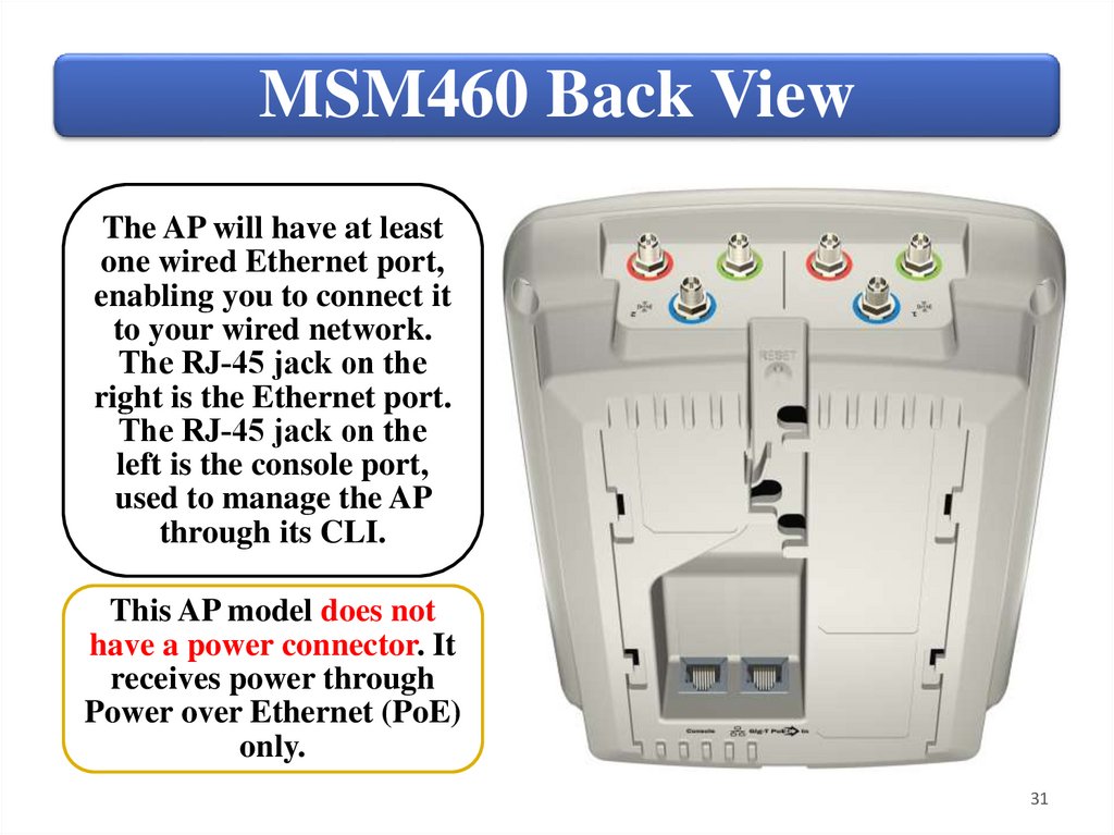
MSM460 Back ViewThe AP will have at least
one wired Ethernet port,
enabling you to connect it
to your wired network.
The RJ‐45 jack on the
right is the Ethernet port.
The RJ‐45 jack on the
left is the console port,
used to manage the AP
through its CLI.
This AP model does not
have a power connector. It
receives power through
Power over Ethernet (PoE)
only.
31
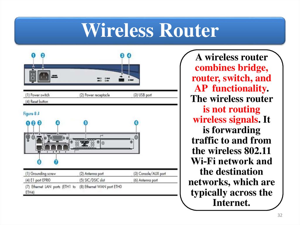
32.
Wireless RouterA wireless router
combines bridge,
router, switch, and
AP functionality.
The wireless router
is not routing
wireless signals. It
is forwarding
traffic to and from
the wireless 802.11
Wi‐Fi network and
the destination
networks, which are
typically across the
Internet.
32
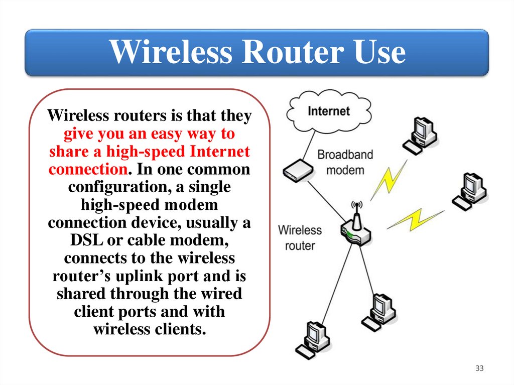
33.
Wireless Router UseWireless routers is that they
give you an easy way to
share a high‐speed Internet
connection. In one common
configuration, a single
high‐speed modem
connection device, usually a
DSL or cable modem,
connects to the wireless
router’s uplink port and is
shared through the wired
client ports and with
wireless clients.
33
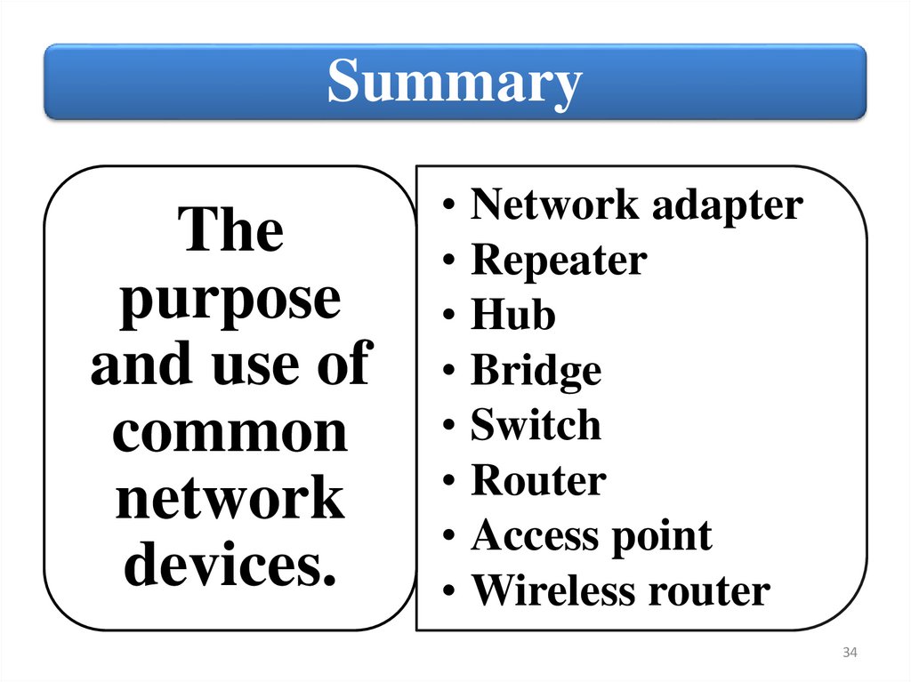
34.
SummaryThe
purpose
and use of
common
network
devices.
• Network adapter
• Repeater
• Hub
• Bridge
• Switch
• Router
• Access point
• Wireless router
34
35.
HardwareFundamentals
2. Describe common switch types
35
36.
SwitchesThere are many different types of network switches
according to the management and configuration option,
number of LAN ports, maximum data rate.
The various types of switches contained in a network are:
Unmanaged switch
Smart managed switch
Managed switch
36
37.
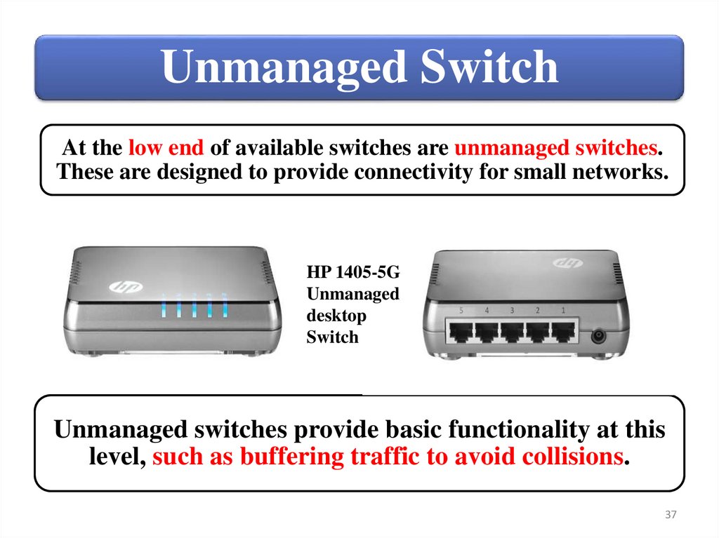
Unmanaged SwitchAt the low end of available switches are unmanaged switches.
These are designed to provide connectivity for small networks.
HP 1405-5G
Unmanaged
desktop
Switch
Unmanaged switches provide basic functionality at this
level, such as buffering traffic to avoid collisions.
37
38.
Unmanaged SwitchOSI
Layer 2
functionality
only
Plugand-play
operation
No
management
interface
No
custom
VLAN
support
Do not
provide any
monitoring
capabilities
38
39.
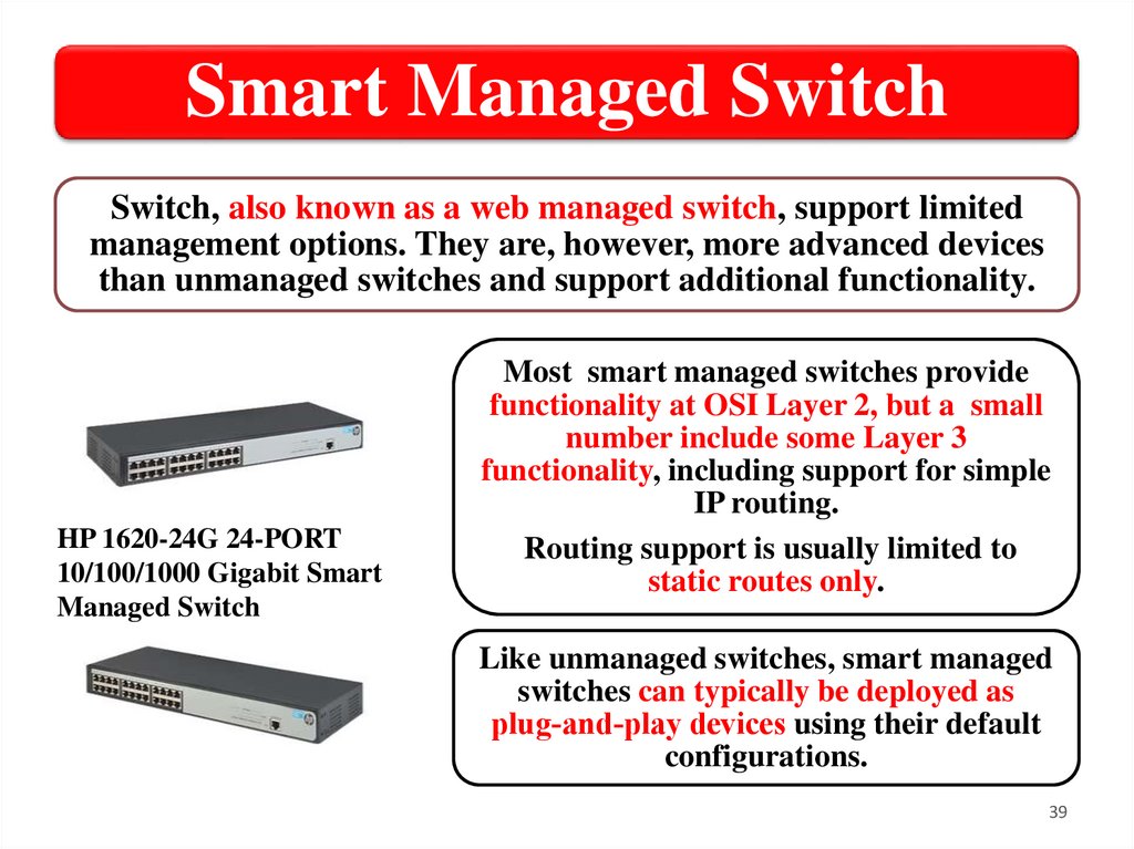
Smart Managed SwitchSwitch, also known as a web managed switch, support limited
management options. They are, however, more advanced devices
than unmanaged switches and support additional functionality.
HP 1620-24G 24-PORT
10/100/1000 Gigabit Smart
Managed Switch
Most smart managed switches provide
functionality at OSI Layer 2, but a small
number include some Layer 3
functionality, including support for simple
IP routing.
Routing support is usually limited to
static routes only.
Like unmanaged switches, smart managed
switches can typically be deployed as
plug‐and‐play devices using their default
configurations.
39
40.
Smart Managed Switch AdvantagesSmart managed
switch has
management access
through a
browser‐based
management
interface, which
allows to view port
statistics and
manage custom
configurations.
Another clear
advantage is that
smart managed
switches include
VLAN support.
You can also
configure link
aggregation to
provide a high‐
bandwidth data
path.
40
41.
Smart Managed Switch LimitedLimited
functionality
• Most switches of this type also have an RJ‐45
console port. Some also have a USB
connection that can be used to connect
directly to the switch. This is similar to the
console connection on managed switches, but
it can typically be used to perform the same
procedures as the web interface.
• Smart managed switches also include limited
SNMP support. SNMP management devices
can automatically discover and remotely
monitor smart managed switches. However,
smart managed switches do not support
remote management from an SNMP
management device.
41
42.
Managed SwitchA network switch is a computer
networking device that connects
devices together on a computer
network.
Switches manage data across a
network by only transmitting a
received message to the device
for which the message was
intended.
Each networked device
connected to a switch can be
identified using a MAC address,
allowing the switch to regulate
the flow of traffic.
HP 7510 Switch with 2 48-port
Gig-T PoE+ Modules and
768Gbps MPU
42
43.
Managed Switch functionalityManaged switches support OSI Layer
2 functionality as well as a wide array
of Layer 3 functionality, such as
dynamic routing.
• Support for dynamic updates to
Dynamic
network destinations and routes
to allow for changes in available
routing.
routes and network conditions.
43
44.
Managed Switch interfacesThese switches support a variety of
manual management options, including:
• CLI (console port or over the network);
• Menu interface (console port or over the
network);
• Web interface (over the network only).
44
45.
Managed Switch and SNMPIn addition, most managed switches can be
monitored and configured through SNMP and an
SNMP management console.
Most managed switches are designed to work with
most manufacturers’ SNMP management devices.
To this end, manufacturers make the switch’s MIB
available for download.
Management
• A collection of management
information base
information about a device for
(MIB).
use with SNMP management
45
46.
Deployment SampleYou might deploy different types of switches in different
physical locations. This allows you to use the type of switch
best suited to each location. It also allows you to save money
by deploying less expensive switches where additional
functionality is not needed.
46
47.
SummarySwitch
management
categories
• Unmanaged switch
• Smart managed
switch
• Managed switch
Switch deployment
47
48.
HardwareFundamentals
3. Configure custom VLANs
48
49.
Virtual LANsA Virtual LAN (VLAN) is any
broadcast domain that is partitioned
|pɑːˈtɪʃənd| and isolated in a
computer network.
VLAN can be created on a Layer 2
switch to reduce the size of broadcast
domains to improve network
performance.
The primary difference between
VLAN and subnet is that a VLAN
is implemented at Layer 2 and a
subnet is implemented at Layer 3.
Also, a subnet is based on location
(physical connection), and a VLAN
is based on port configuration
(logical connection).
Subnet A
Subnet B
49
50.
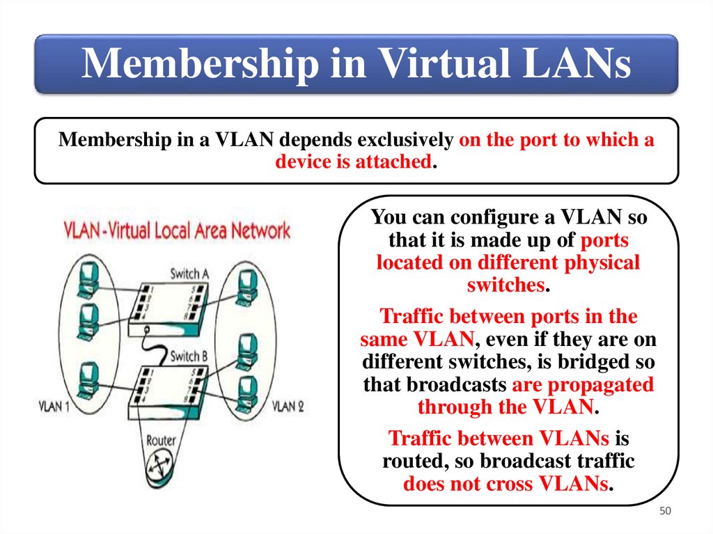
Membership in Virtual LANsMembership in a VLAN depends exclusively on the port to which a
device is attached.
You can configure a VLAN so
that it is made up of ports
located on different physical
switches.
Traffic between ports in the
same VLAN, even if they are on
different switches, is bridged so
that broadcasts are propagated
through the VLAN.
Traffic between VLANs is
routed, so broadcast traffic
does not cross VLANs.
50
51.
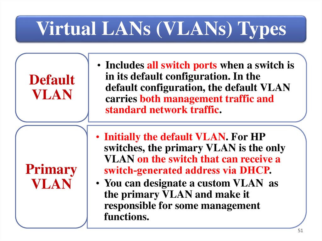
Virtual LANs (VLANs) TypesDefault
VLAN
Primary
VLAN
• Includes all switch ports when a switch is
in its default configuration. In the
default configuration, the default VLAN
carries both management traffic and
standard network traffic.
• Initially the default VLAN. For HP
switches, the primary VLAN is the only
VLAN on the switch that can receive a
switch‐generated address via DHCP.
• You can designate a custom VLAN as
the primary VLAN and make it
responsible for some management
functions.
51
52.
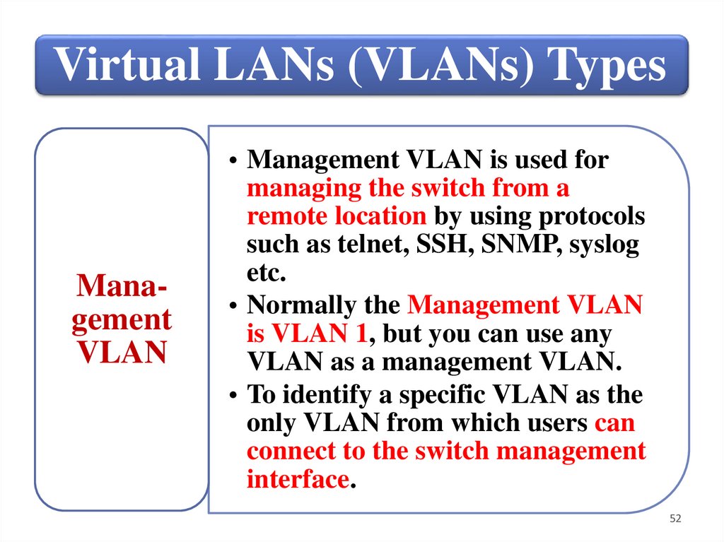
Virtual LANs (VLANs) TypesManagement
VLAN
• Management VLAN is used for
managing the switch from a
remote location by using protocols
such as telnet, SSH, SNMP, syslog
etc.
• Normally the Management VLAN
is VLAN 1, but you can use any
VLAN as a management VLAN.
• To identify a specific VLAN as the
only VLAN from which users can
connect to the switch management
interface.
52
53.
Virtual LANs (VLANs) TypesSecure
Management
VLAN
Voice
VLAN
• When created as a custom VLAN, the
secure management VLAN is an
isolated network specifically used for
switch management. Access to
management functions is then limited
to only those ports configured as secure
management VLAN members. Traffic
cannot be routed to or from this VLAN.
• Custom VLAN that can be created to
isolate VoIP traffic from other network
traffic.
53
54.
Creating a VLAN• Define the VLAN
The
name and ID;
basic
steps for • Transfer ports from
the default VLAN to
creating the new VLAN;
a custom • Assign an IP address
VLAN
to the VLAN
are:
(optional).
54
55.
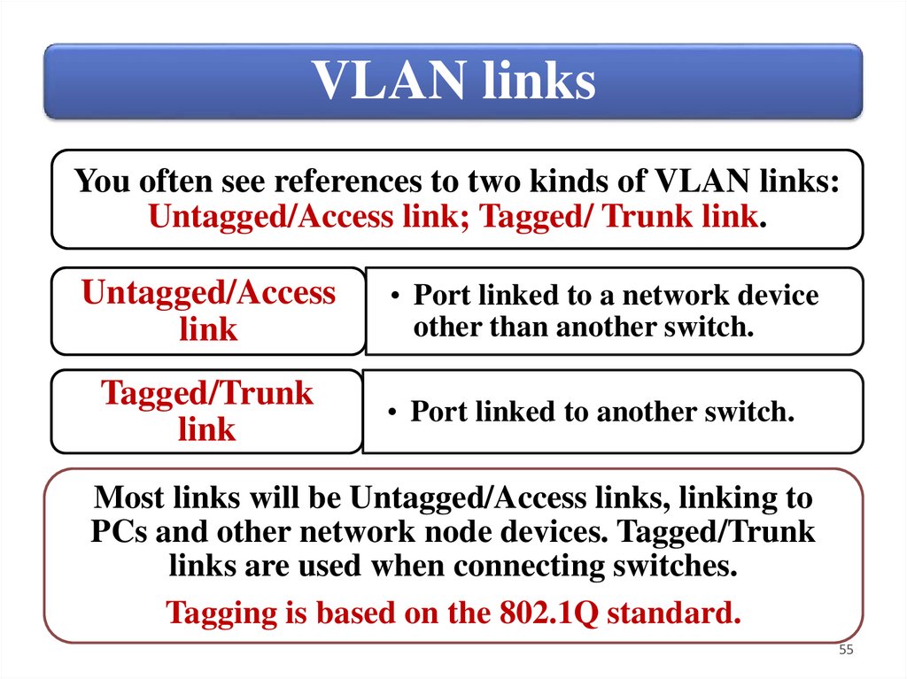
VLAN linksYou often see references to two kinds of VLAN links:
Untagged/Access link; Tagged/ Trunk link.
Untagged/Access
link
Tagged/Trunk
link
• Port linked to a network device
other than another switch.
• Port linked to another switch.
Most links will be Untagged/Access links, linking to
PCs and other network node devices. Tagged/Trunk
links are used when connecting switches.
Tagging is based on the 802.1Q standard.
55
56.
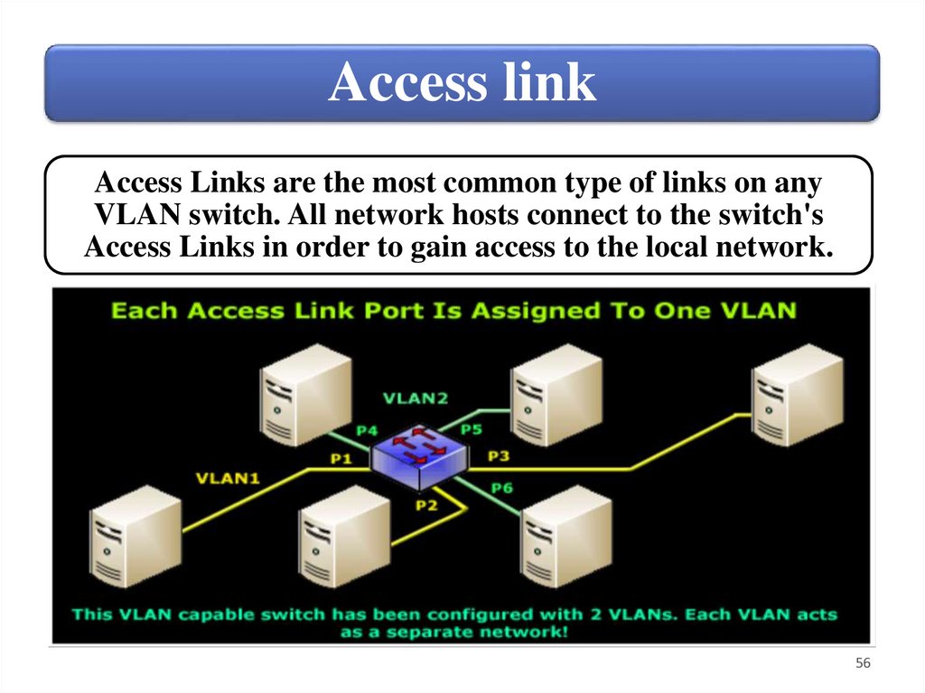
Access linkAccess Links are the most common type of links on any
VLAN switch. All network hosts connect to the switch's
Access Links in order to gain access to the local network.
56
57.
Trunk linkA Trunk Link, or “Trunk” is a port configured to carry packets
for any VLAN. These type of ports are usually found in
connections between switches. Trunk links are also used to
provide high‐bandwidth communication paths when configuring
multi‐switch VLANs.
57
58.
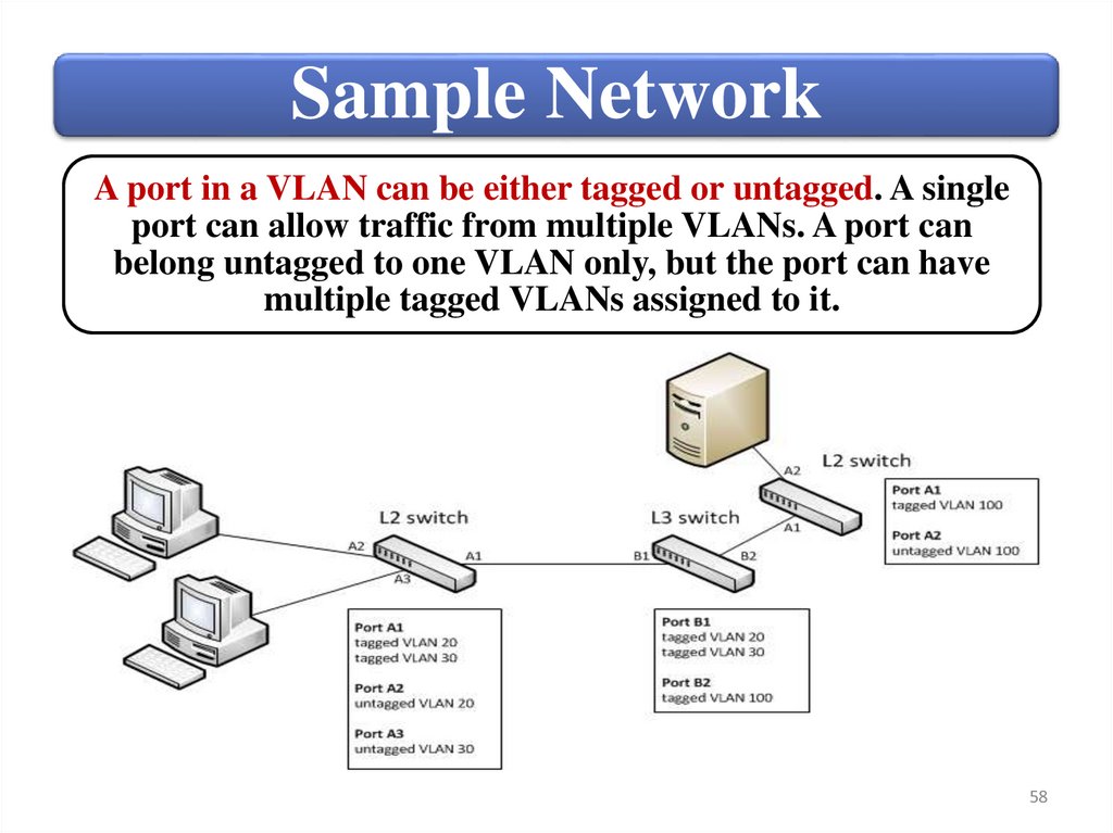
Sample NetworkA port in a VLAN can be either tagged or untagged. A single
port can allow traffic from multiple VLANs. A port can
belong untagged to one VLAN only, but the port can have
multiple tagged VLANs assigned to it.
58
59.
SummaryVLAN types and use
Creating and managing custom
VLANs
Viewing and managing ports
59
60.
HardwareFundamentals
4. Identify switch management
interfaces.
60
61.
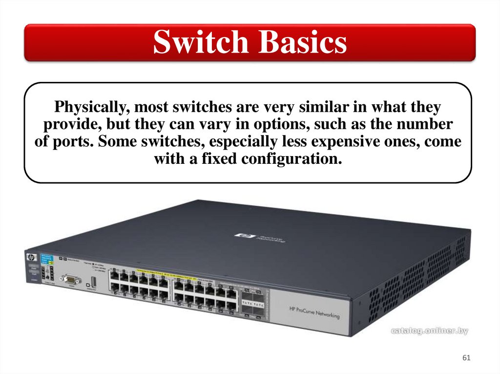
Switch BasicsPhysically, most switches are very similar in what they
provide, but they can vary in options, such as the number
of ports. Some switches, especially less expensive ones, come
with a fixed configuration.
61
62.
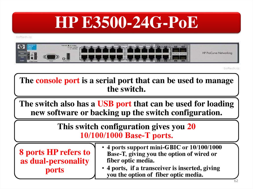
HP E3500-24G-PoEThe console port is a serial port that can be used to manage
the switch.
The switch also has a USB port that can be used for loading
new software or backing up the switch configuration.
This switch configuration gives you 20
10/100/1000 Base‐T ports.
8 ports HP refers to
as dual-personality
ports
• 4 ports support mini‐GBIC or 10/100/1000
Base‐T, giving you the option of wired or
fiber optic media.
• 4 ports, if a transceiver is inserted, giving
you the option of fiber optic media.
62
63.
HP 5406zl‐48G switchThis model switch provide for installation of up to six
modules. The management module hosts the console and
USB ports. It also has indicator LEDs that provide status
information about the switch and installed modules.
63
64.
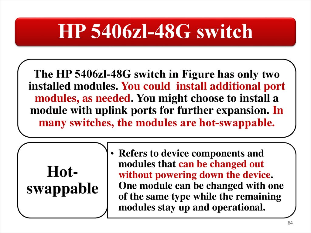
HP 5406zl‐48G switchThe HP 5406zl‐48G switch in Figure has only two
installed modules. You could install additional port
modules, as needed. You might choose to install a
module with uplink ports for further expansion. In
many switches, the modules are hot‐swappable.
Hotswappable
• Refers to device components and
modules that can be changed out
without powering down the device.
One module can be changed with one
of the same type while the remaining
modules stay up and operational.
64
65.
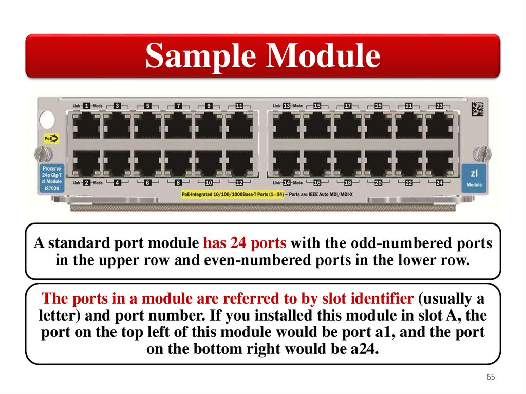
Sample ModuleA standard port module has 24 ports with the odd‐numbered ports
in the upper row and even‐numbered ports in the lower row.
The ports in a module are referred to by slot identifier (usually a
letter) and port number. If you installed this module in slot A, the
port on the top left of this module would be port a1, and the port
on the bottom right would be a24.
65
66.
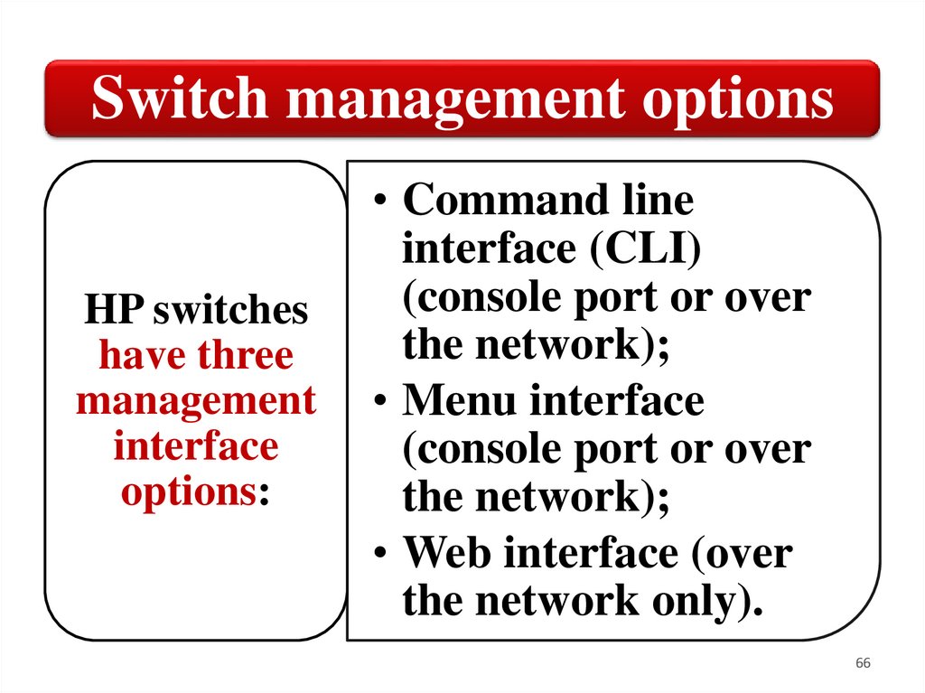
Switch management optionsHP switches
have three
management
interface
options:
• Command line
interface (CLI)
(console port or over
the network);
• Menu interface
(console port or over
the network);
• Web interface (over
the network only).
66
67.
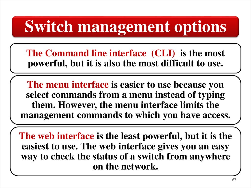
Switch management optionsThe Command line interface (CLI) is the most
powerful, but it is also the most difficult to use.
The menu interface is easier to use because you
select commands from a menu instead of typing
them. However, the menu interface limits the
management commands to which you have access.
The web interface is the least powerful, but it is the
easiest to use. The web interface gives you an easy
way to check the status of a switch from anywhere
on the network.
67
68.
SummarySwitches are a fundamental part of most
networks and there are many different types
of switches.
Management
interface
options
• CLI
• Menu interface
• Web interface
68