


 Промышленность
Похожие презентации:


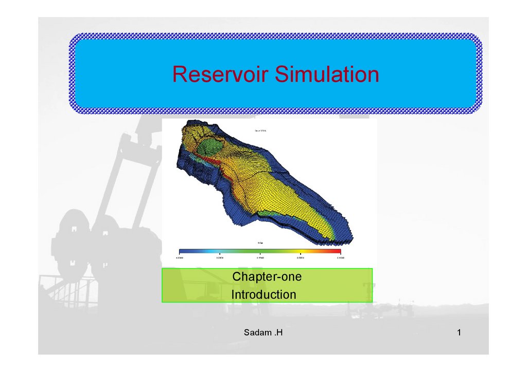
Reservoir Simulation
1.
Reservoir SimulationChapter-one
Introduction
Sadam .H
1
2.
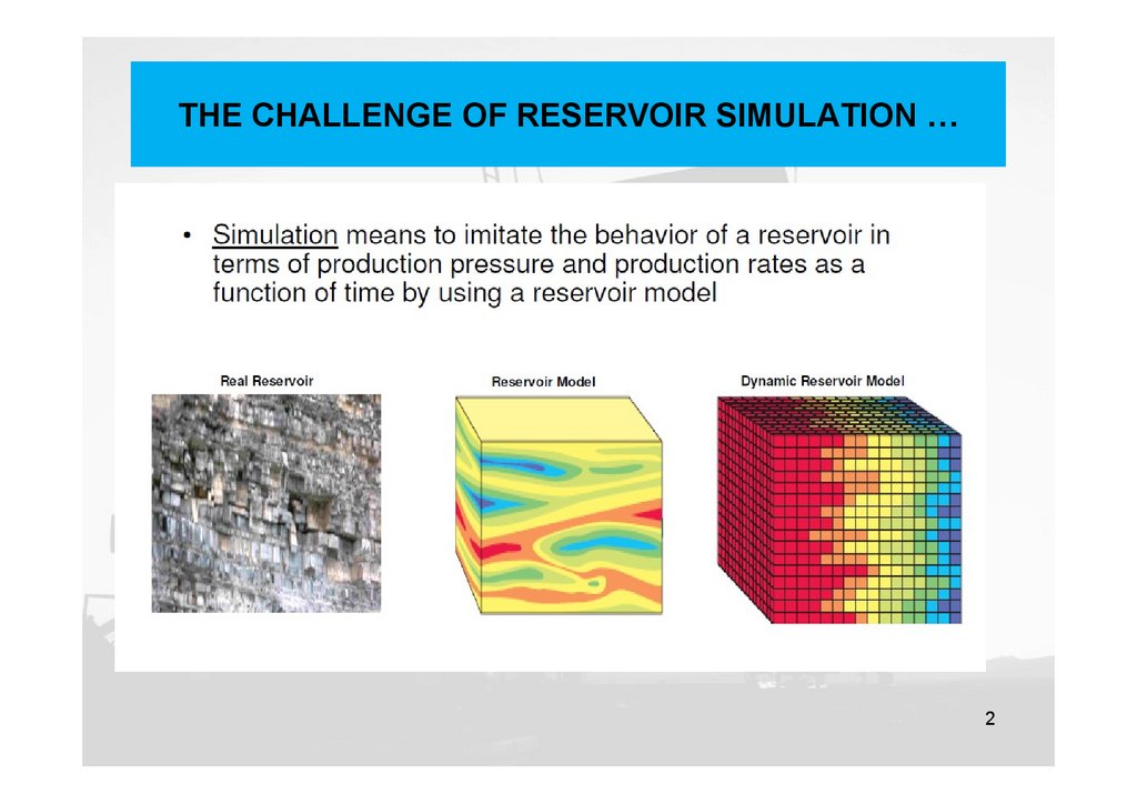
THE CHALLENGE OF RESERVOIR SIMULATION …2
3.
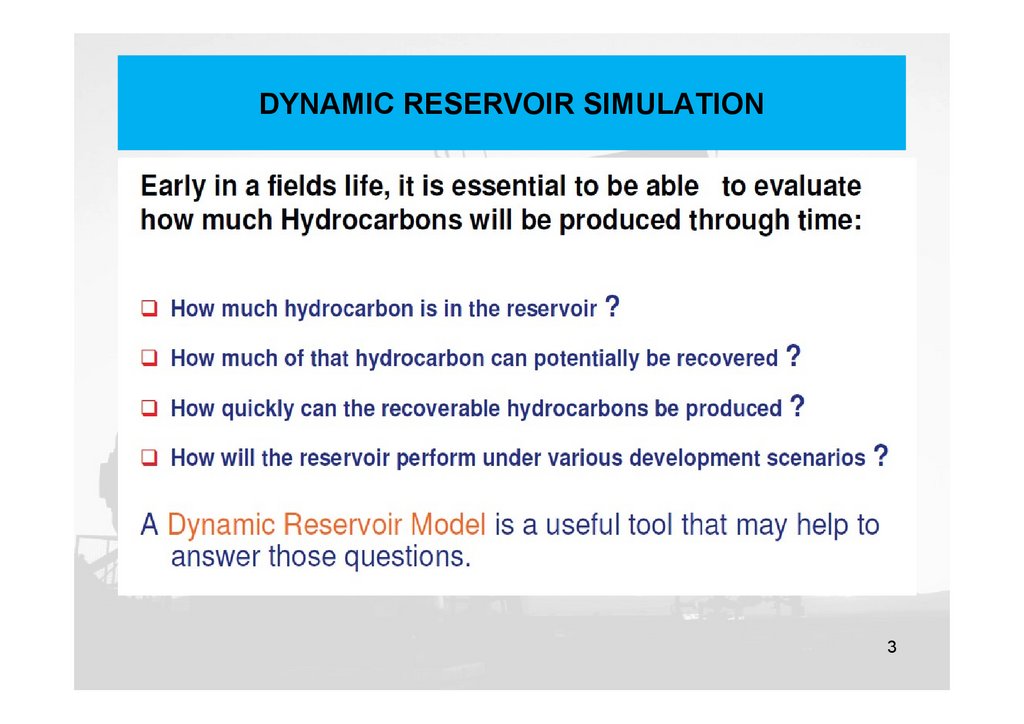
DYNAMIC RESERVOIR SIMULATION3
4.
Incentives for running a flow simulation4
5.
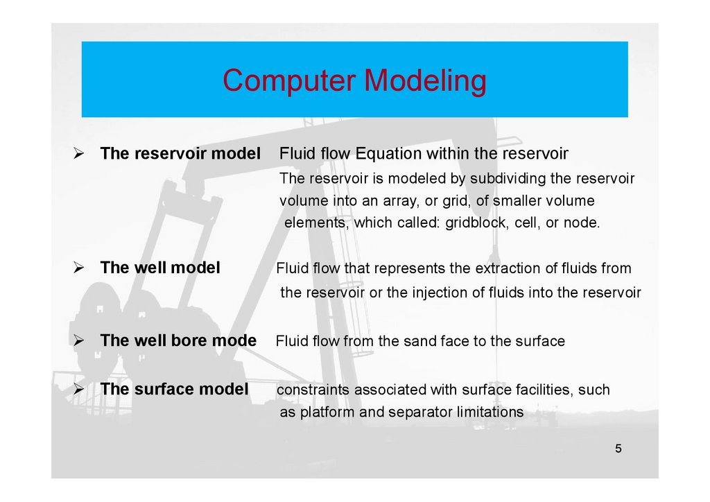
Computer ModelingThe reservoir model
Fluid flow Equation within the reservoir
The reservoir is modeled by subdividing the reservoir
volume into an array, or grid, of smaller volume
elements, which called: gridblock, cell, or node.
The well model
Fluid flow that represents the extraction of fluids from
the reservoir or the injection of fluids into the reservoir
The well bore mode
Fluid flow from the sand face to the surface
The surface model
constraints associated with surface facilities, such
as platform and separator limitations
5
6.
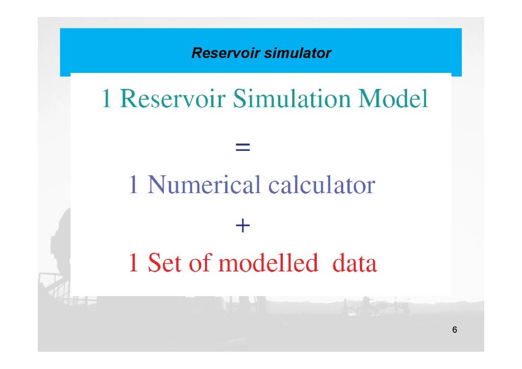
Reservoir simulator6
7.
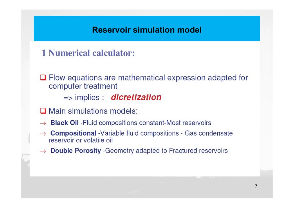
Reservoir simulation model7
8.
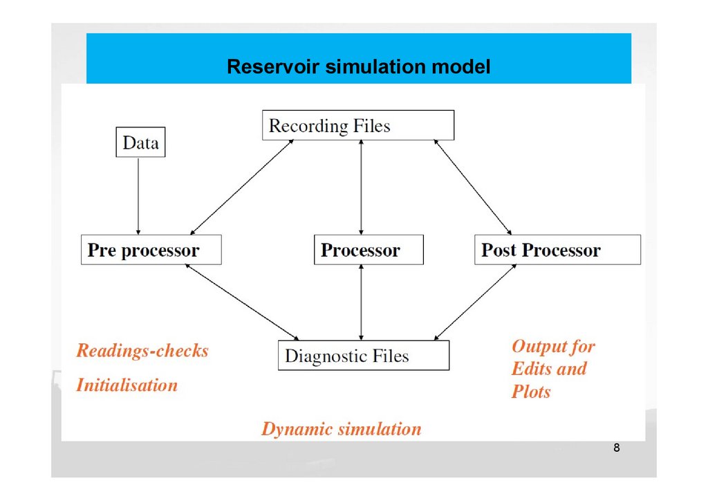
Reservoir simulation model8
9.
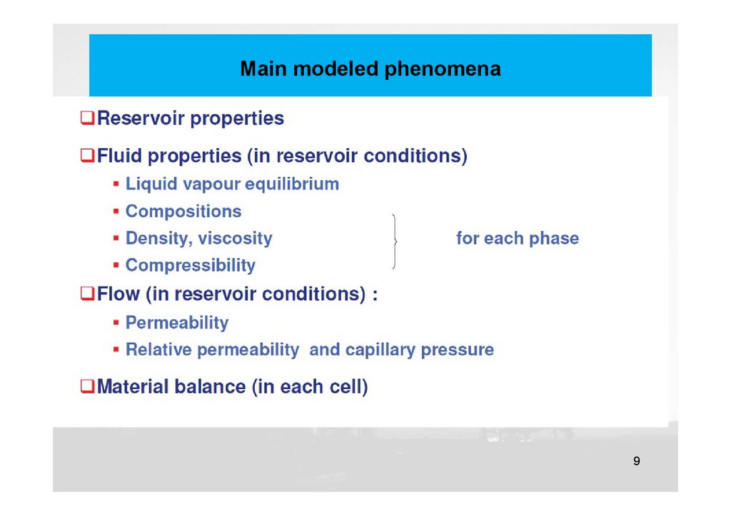
Main modeled phenomena9
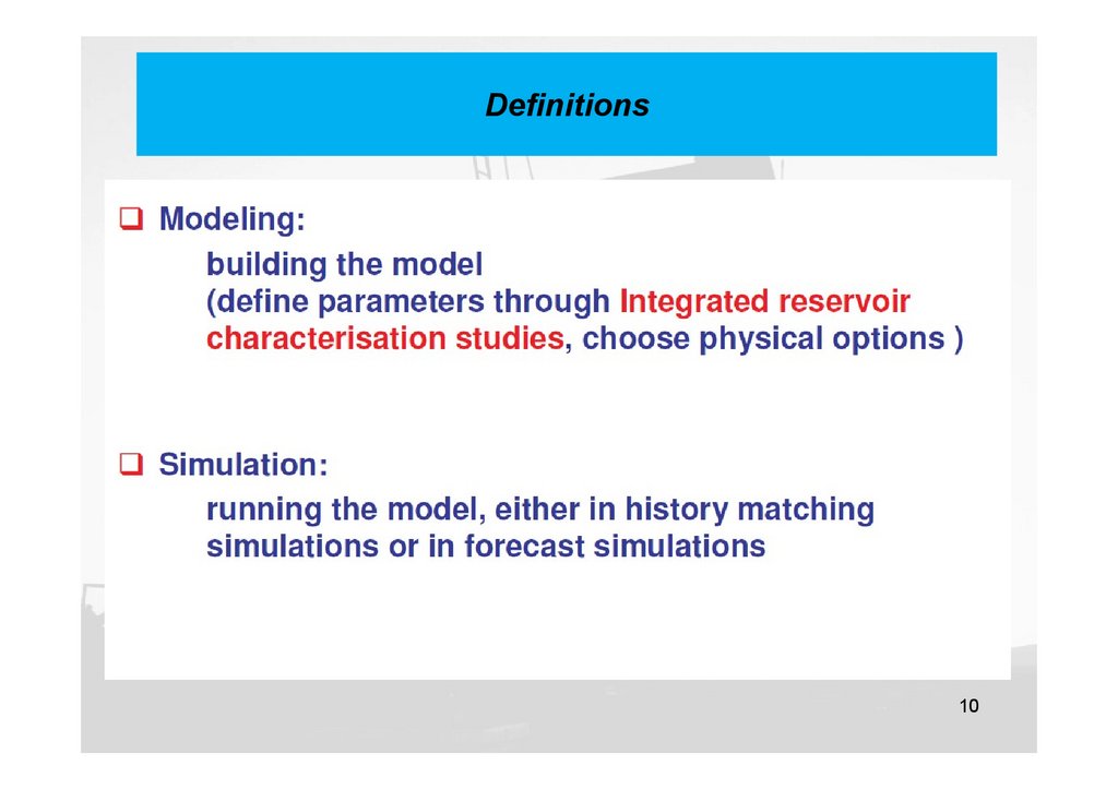
10.
Definitions10
11.
Types of models11
12.
Types of simulators12
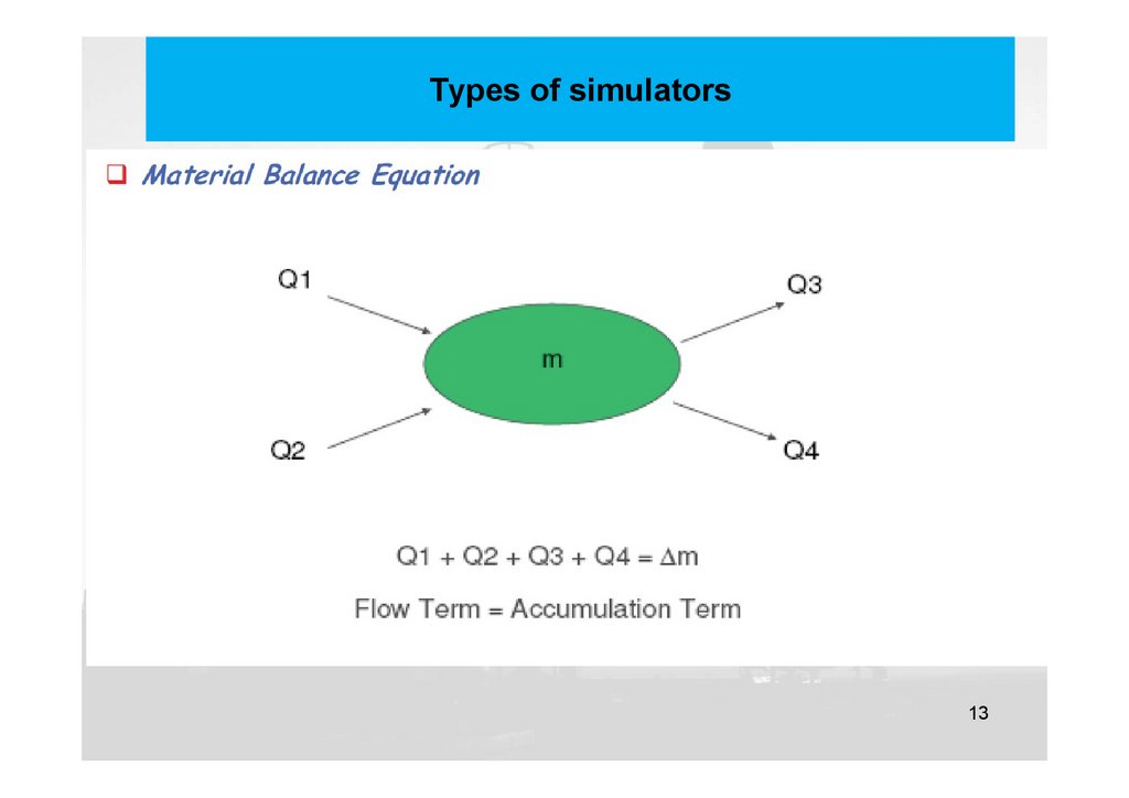
13.
Types of simulators13
14.
Black Oil model14
15.
NUMERICAL MODELS: DISCRETIZATION15
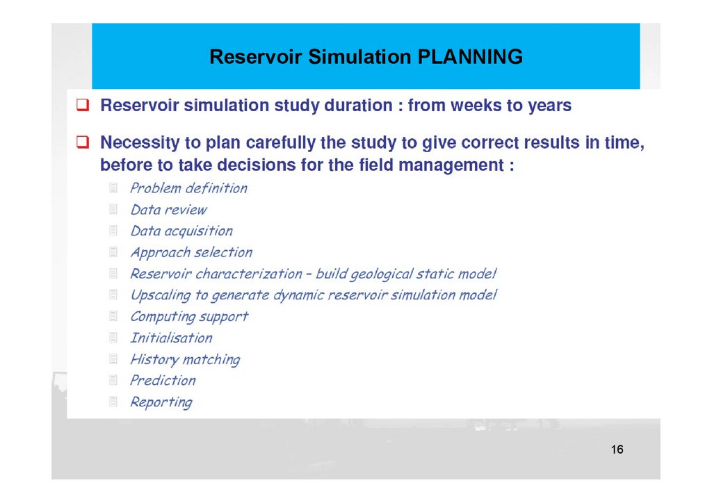
16.
Reservoir Simulation PLANNING16
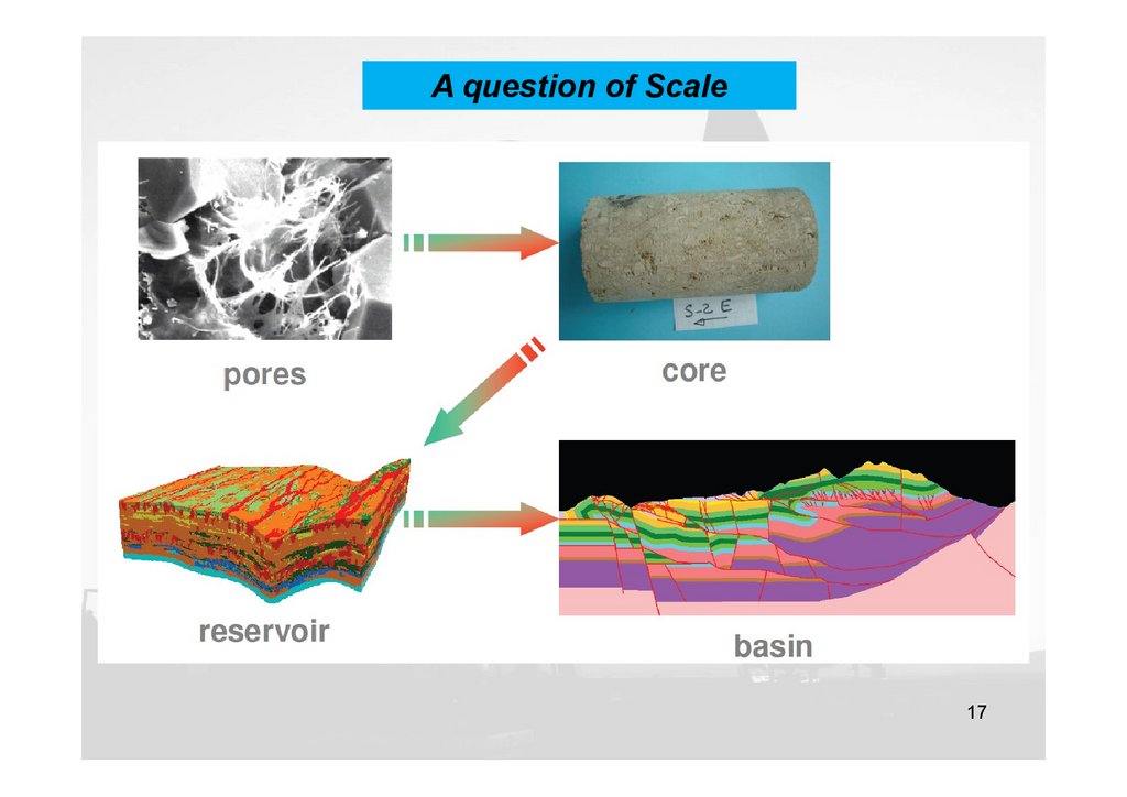
17.
A question of Scale17
18.
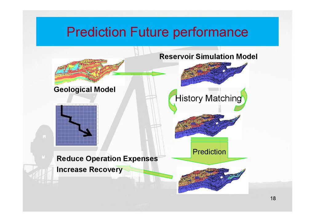
Prediction Future performanceReservoir Simulation Model
Geological Model
Reduce Operation Expenses
Increase Recovery
History Matching
Prediction
18
19.
Problem definition19
20.
Data review20
21.
Main Types of Data21
22.
Study approach22
23.
Study approach23
24.
GRID TYPES24
25.
GRID TYPES25
26.
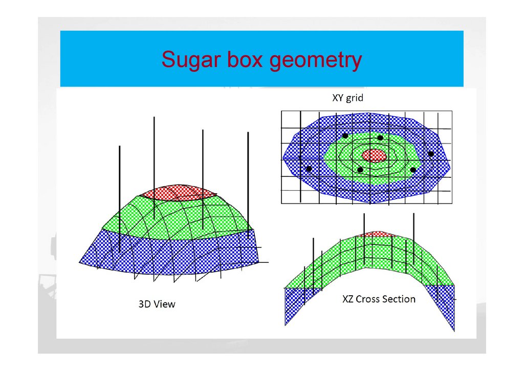
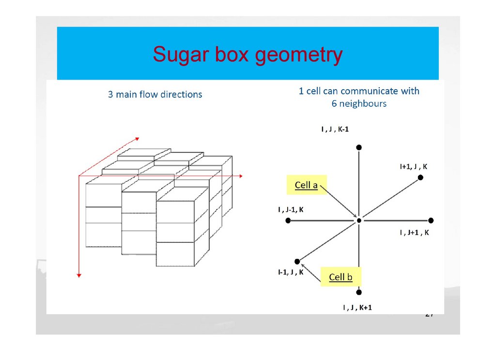
Sugar box geometry26
27.
Sugar box geometry27
28.
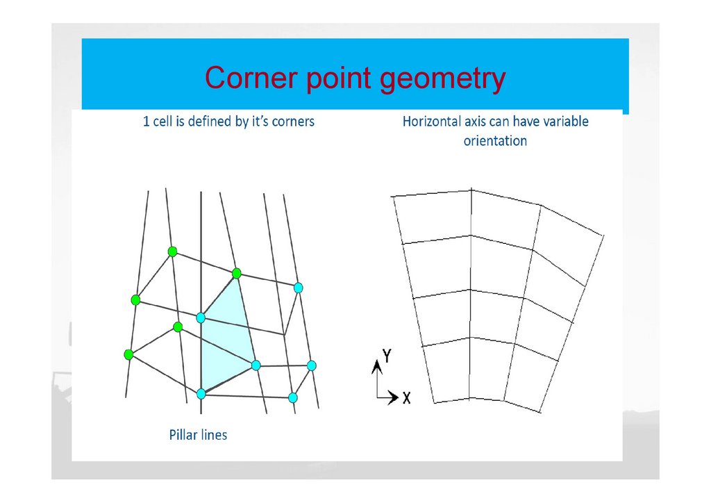
Corner point geometry28
29.
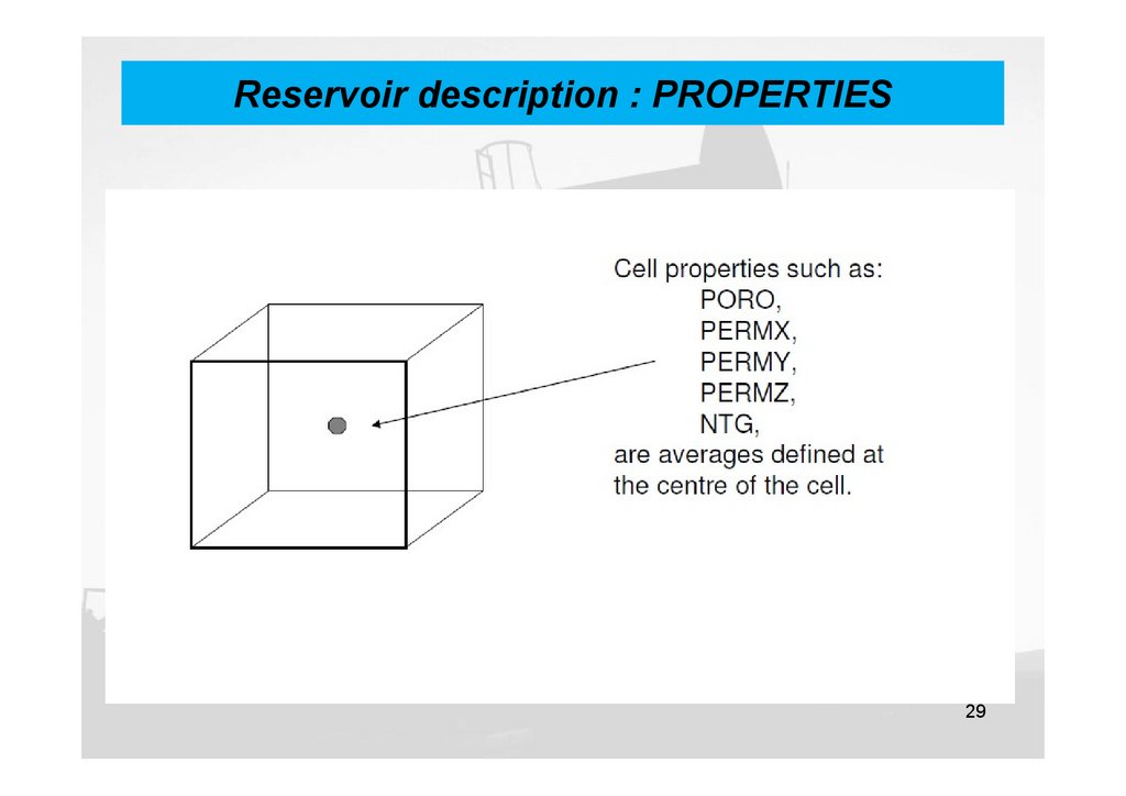
Reservoir description : PROPERTIES29
30.
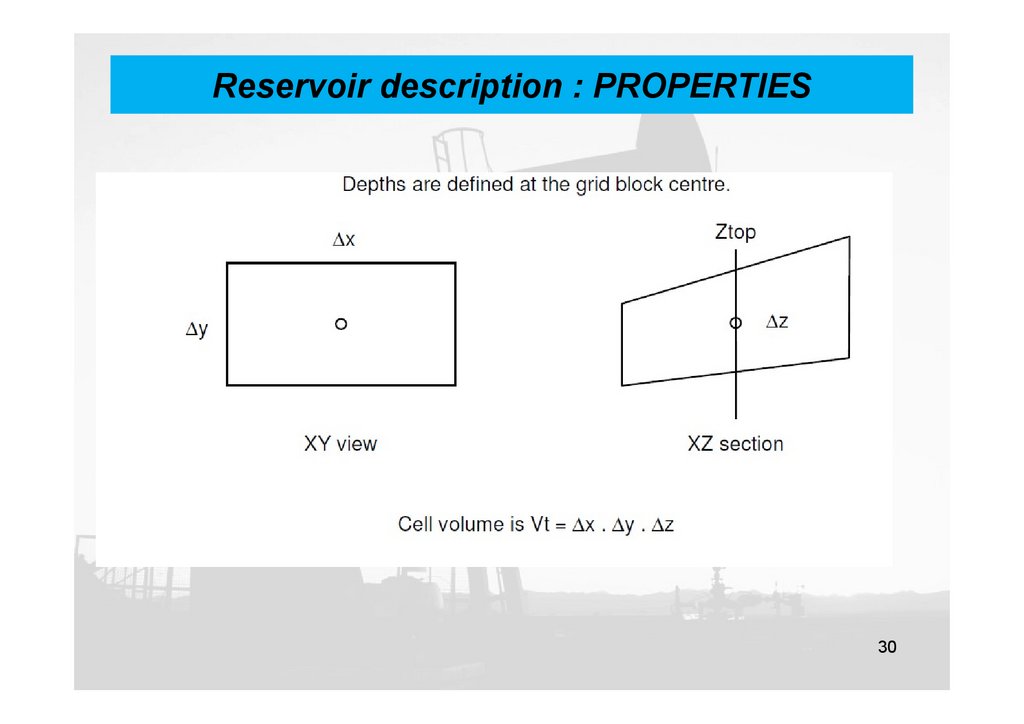
Reservoir description : PROPERTIES30
31.
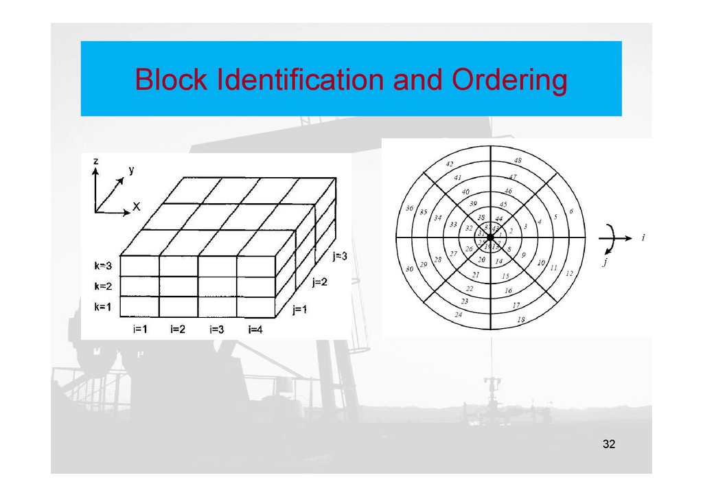
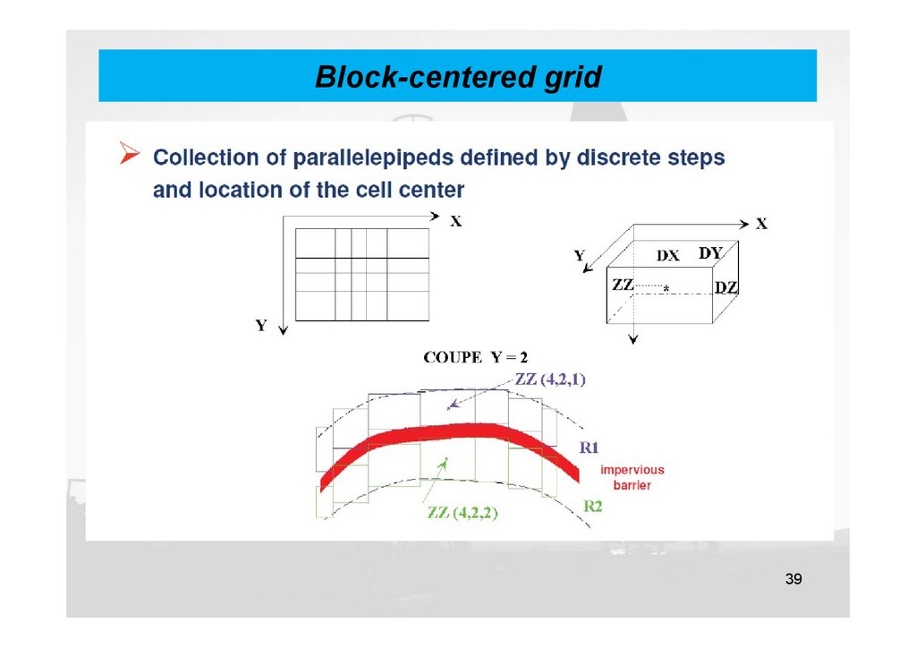
Reservoir DiscritizationDefination: the reservoir is described by a set of gridblocks (or
gridpoints) whose properties, dimensions, boundaries, and locations in the
reservoir are well defined.
Block centered grid
Point distributed grid
i-1
i
i+1
ΔY
ΔX
ΔX
31
32.
Block Identification and Ordering32
33.
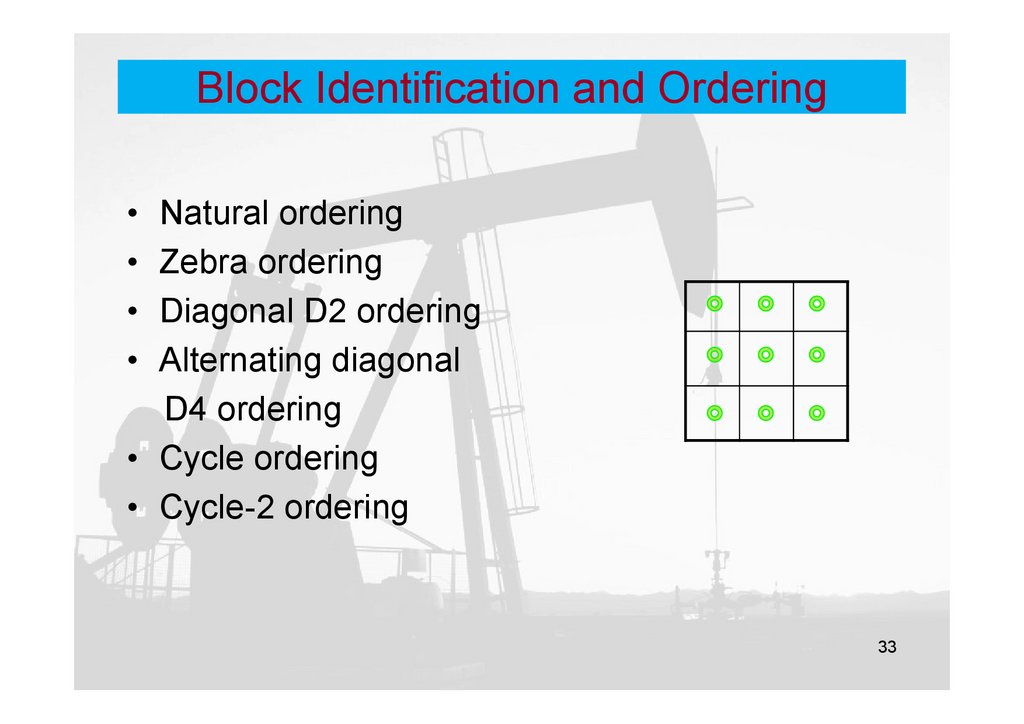
Block Identification and Ordering• Natural ordering
• Zebra ordering
• Diagonal D2 ordering
• Alternating diagonal
D4 ordering
• Cycle ordering
• Cycle-2 ordering
33
34.
GRID SIZE SELECTION34
35.
ACTIVE and DEAD CELLS35
36.
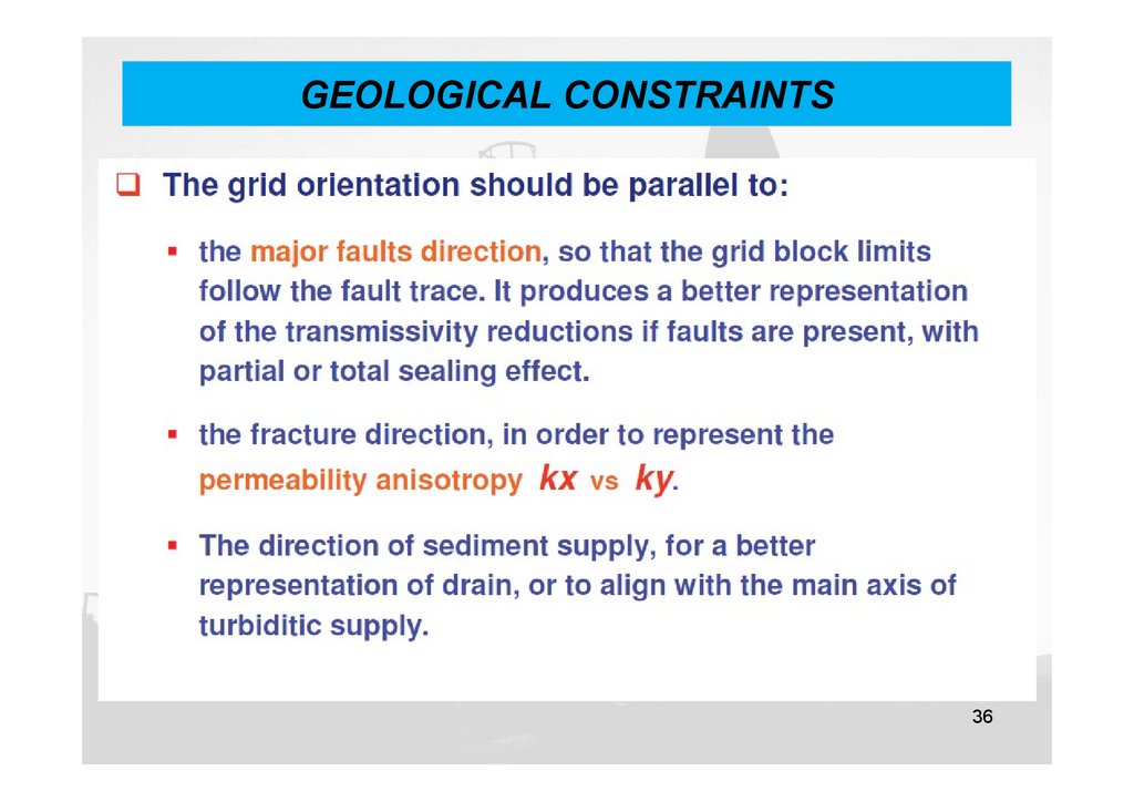
GEOLOGICAL CONSTRAINTS36
37.
CHOICE OF VERTICAL DISCRETIZATION37
38.
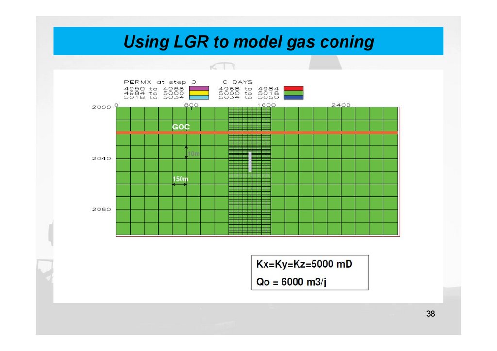
Using LGR to model gas coning38
39.
Block-centered grid39
40.
Block-centered grid40
41.
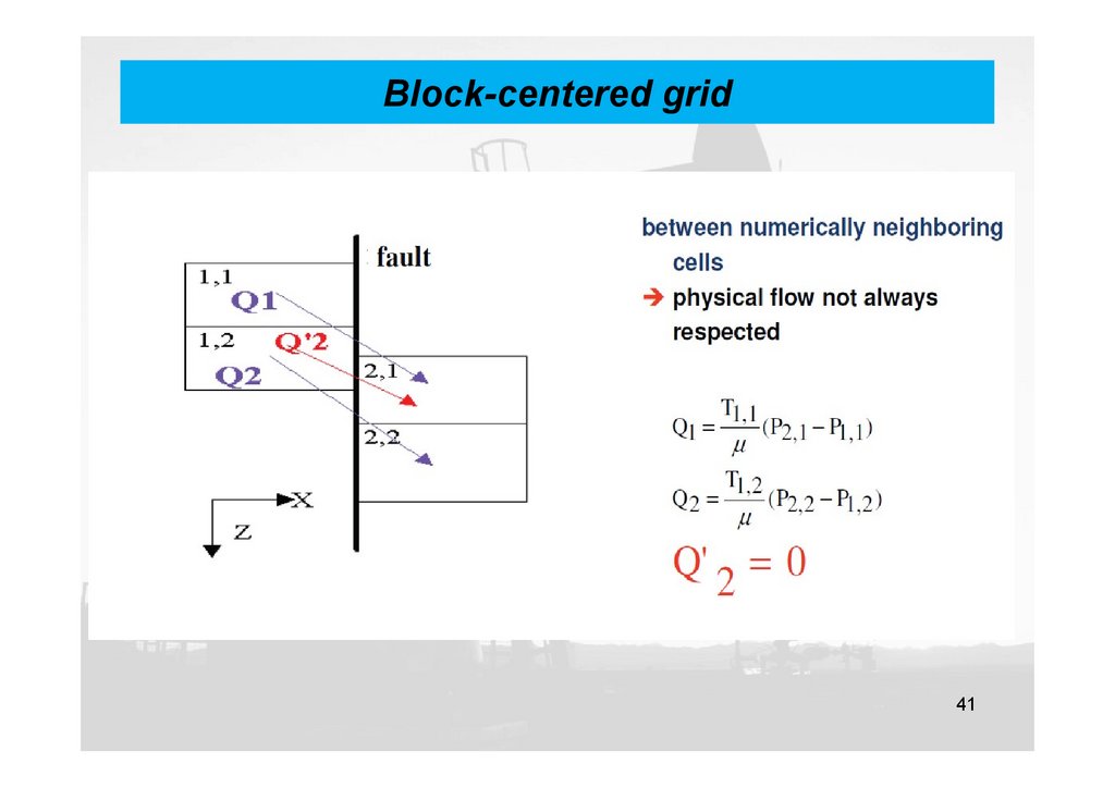
Block-centered grid41
42.
Dip or fault ?42
43.
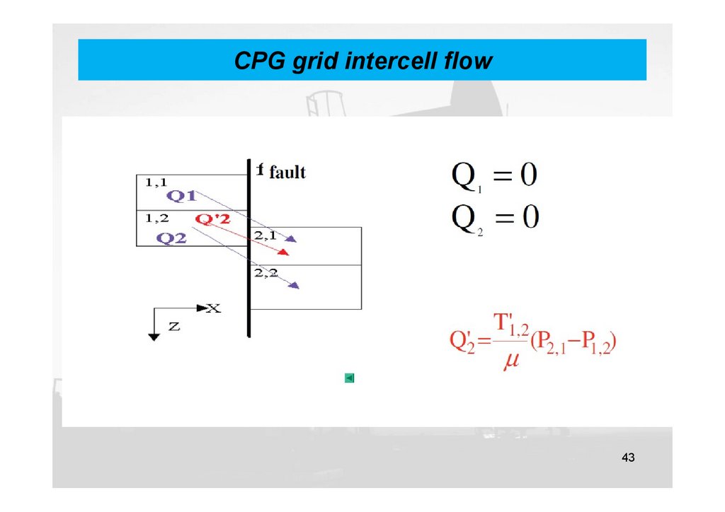
CPG grid intercell flow43
44.
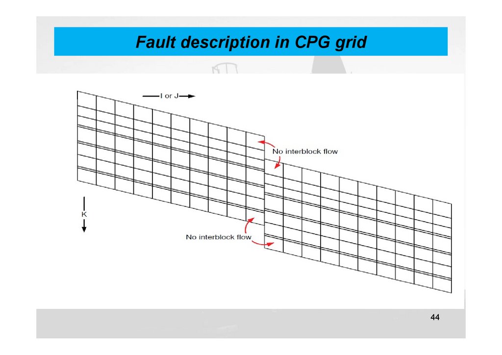
Fault description in CPG grid44
45.
Example of CPG reservoir model45
46.
Fault description in CPG grid46
47.
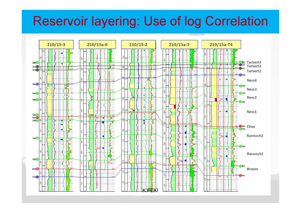
Reservoir layering: Use of log CorrelationK.FEKI
47
48.
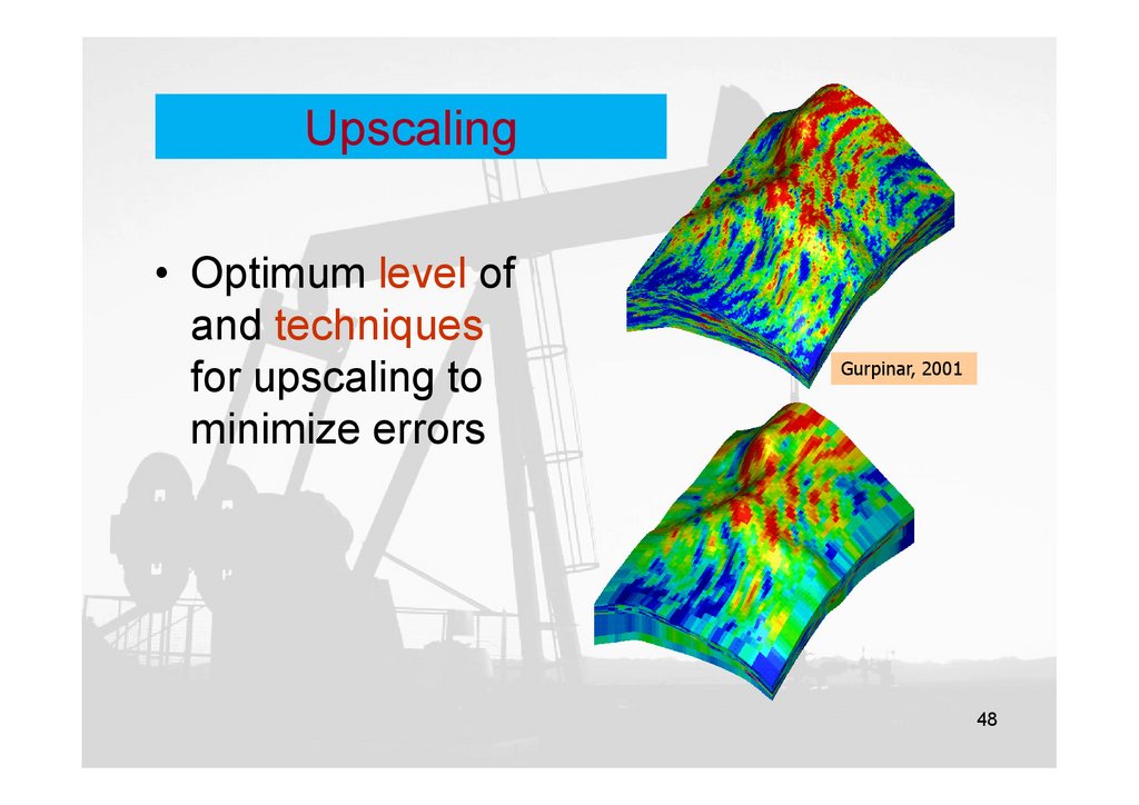
Upscaling• Optimum level of
and techniques
for upscaling to
minimize errors
Gurpinar, 2001
48
49.
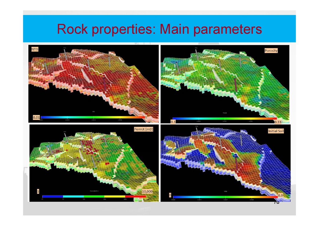
Rock properties: Main parameters49
50.
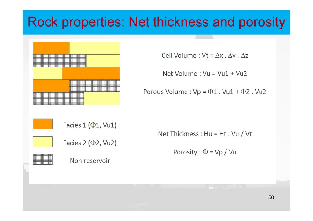
Rock properties: Net thickness and porosity50
51.
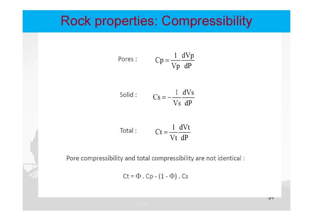
Rock properties: Compressibility51
52.
Rock properties: Compressibility52
53.
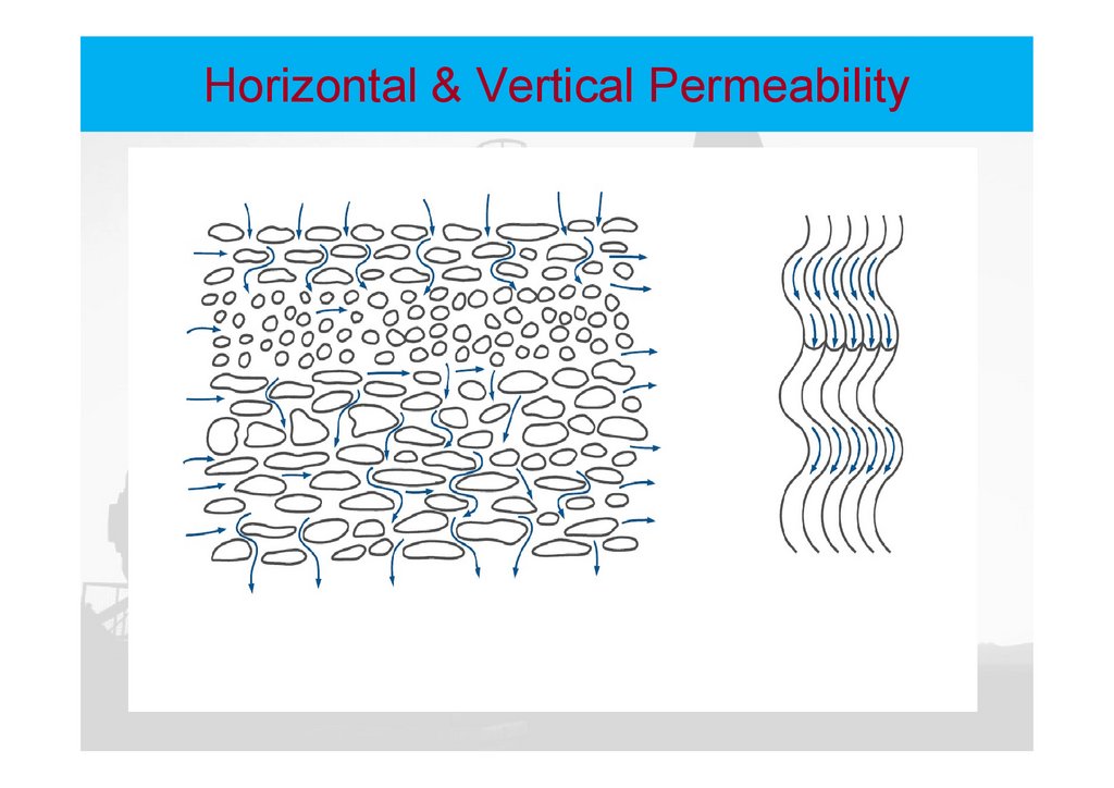
Horizontal & Vertical Permeability53
54.
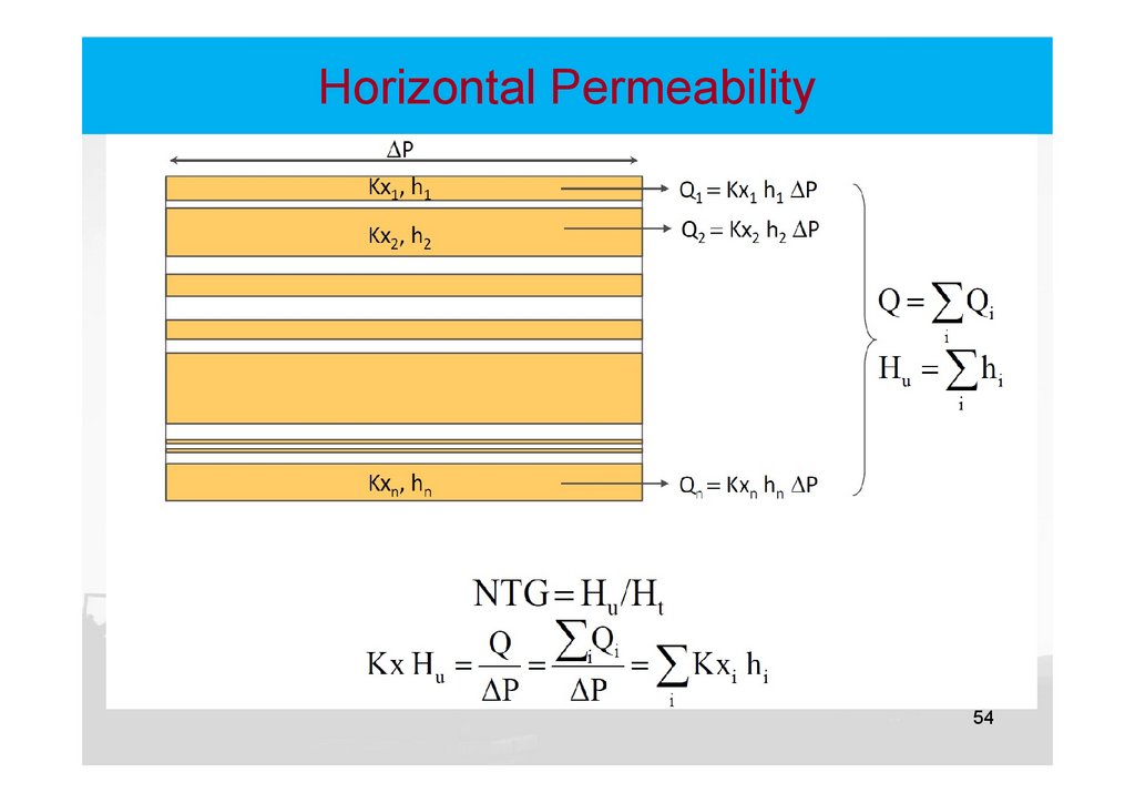
Horizontal Permeability54
55.
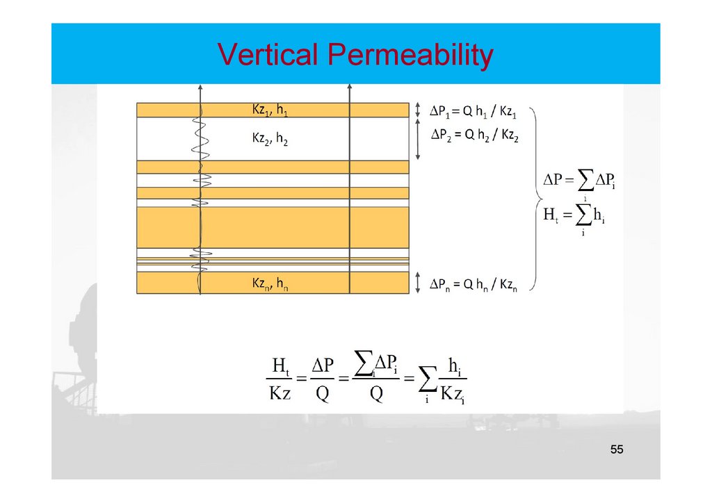
Vertical Permeability55
56.
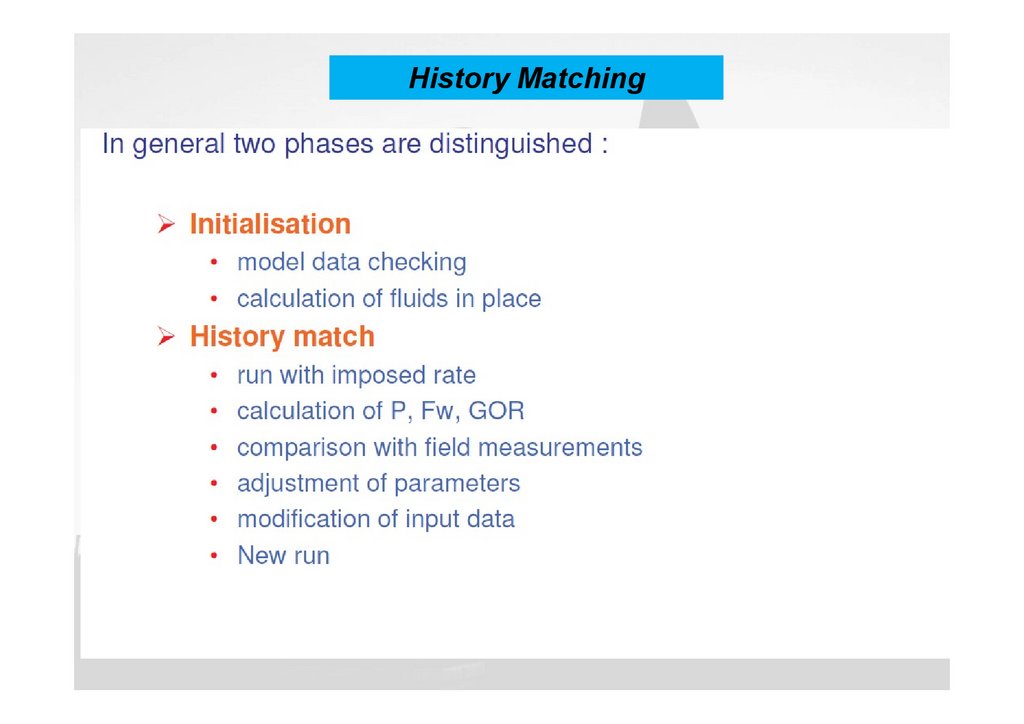
History Matching56
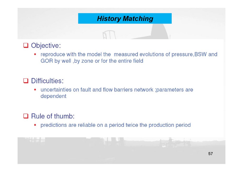
57.
History Matching57
58.
History Matching58
59.
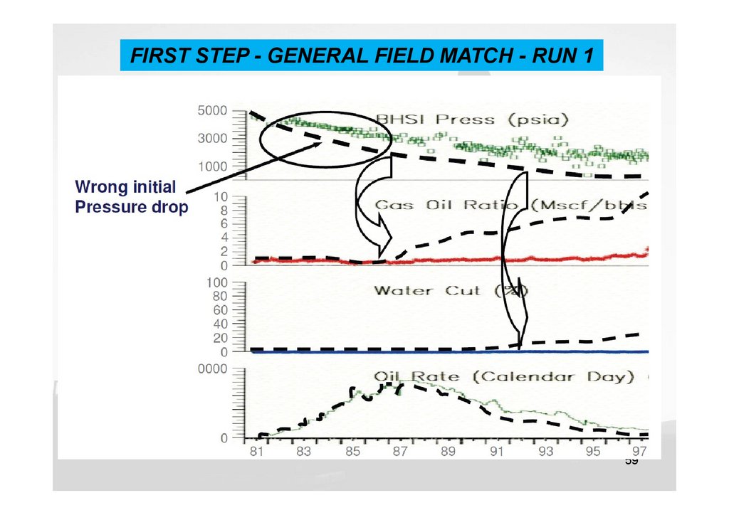
FIRST STEP - GENERAL FIELD MATCH - RUN 159
60.
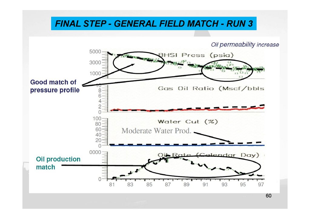
FINAL STEP - GENERAL FIELD MATCH - RUN 360
61.
Predictions61
62.
Predictions62
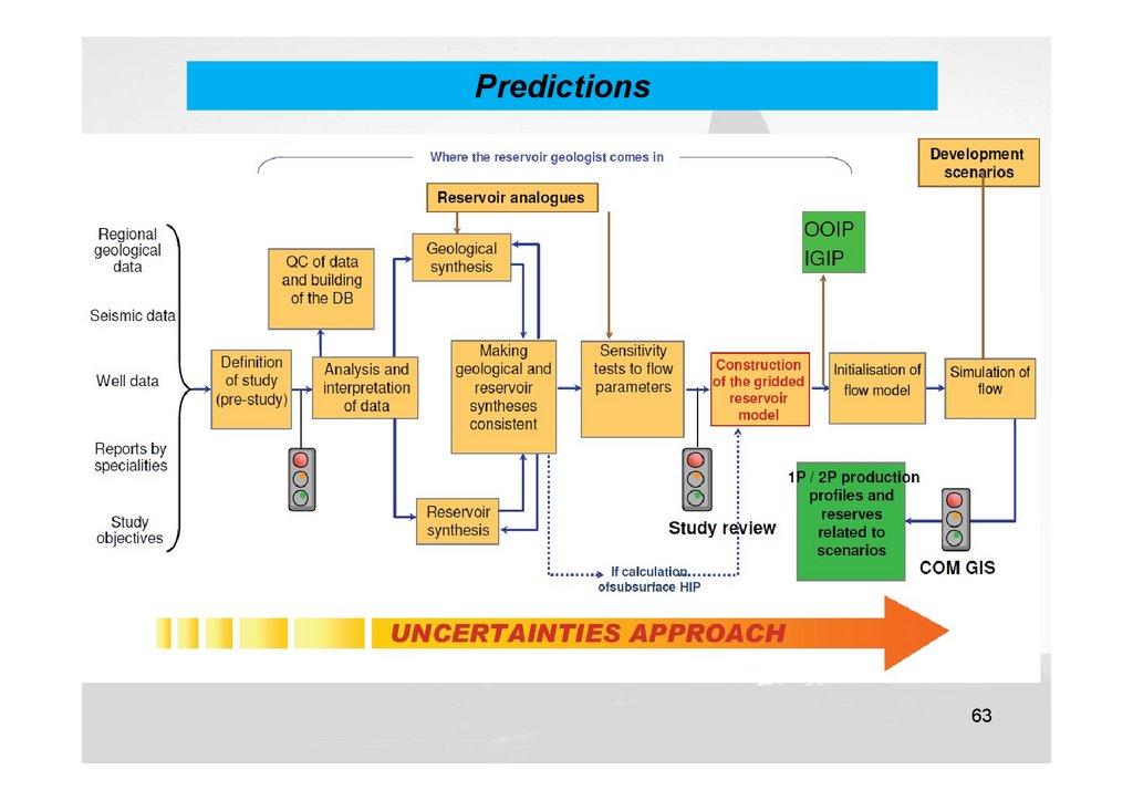
63.
Predictions63
64.
Fluid flow equationsConservation laws
–
Conservation in mass
Assume:
–
–
Isothermal condition
complete and instantaneous phase equilibration in each cell
Conservation in energy
Conservation in momentum
Additional constraints
Wells and facilities
Large number of non-linear equations
64
65.
Fluid flow equationsType of fluid in the reservoir
Flow regimes
Reservoir geometry
Number of flowing fluids in the reservoir
65
66.
Type of fluid in the reservoirIncompressible
Slightly compressible
Compressible
66
67.
Flow regimesSteady State flow
Unsteady State flow
Pseudo Steady State flow
67
68.
Reservoir geometryRadial flow
Linear flow
Spherical and Hemispherical flow
68
69.
Number of flowing fluids in thereservoir
Single Phase flow
Two phase flow
Three phase flow
69
70.
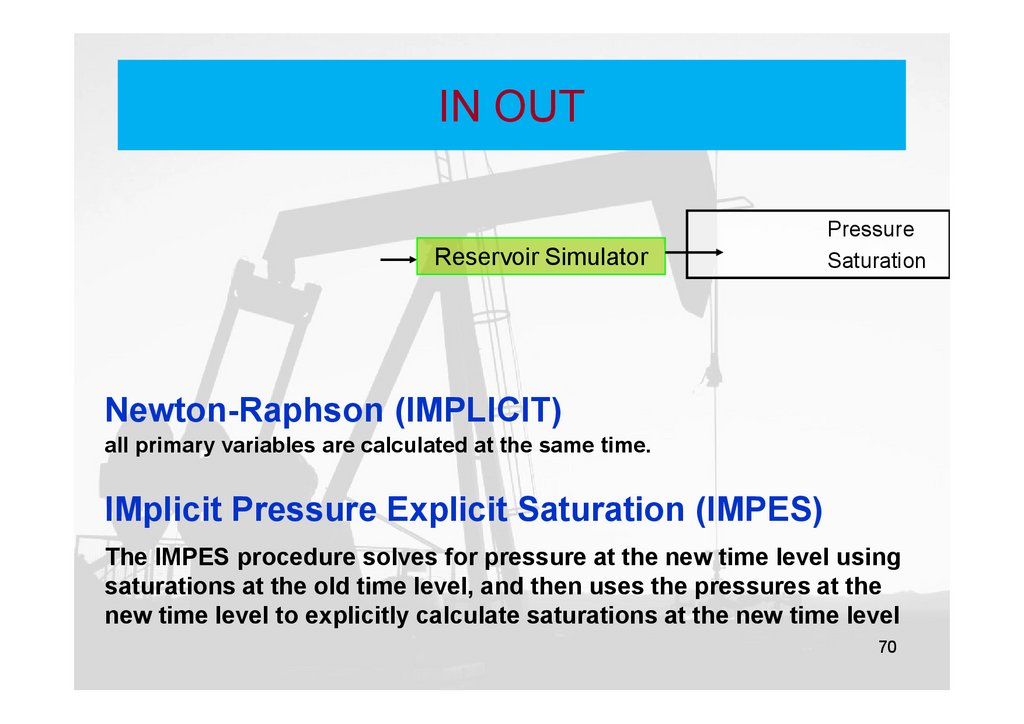
IN OUTReservoir Simulator
Pressure
Saturation
Newton-Raphson (IMPLICIT)
all primary variables are calculated at the same time.
IMplicit Pressure Explicit Saturation (IMPES)
The IMPES procedure solves for pressure at the new time level using
saturations at the old time level, and then uses the pressures at the
new time level to explicitly calculate saturations at the new time level
70
71.
Numerical ModelsBlack oil model
o
o
Depletion
Water Injection
Component: oil water gas
Phase: Oil water gas
71
72.
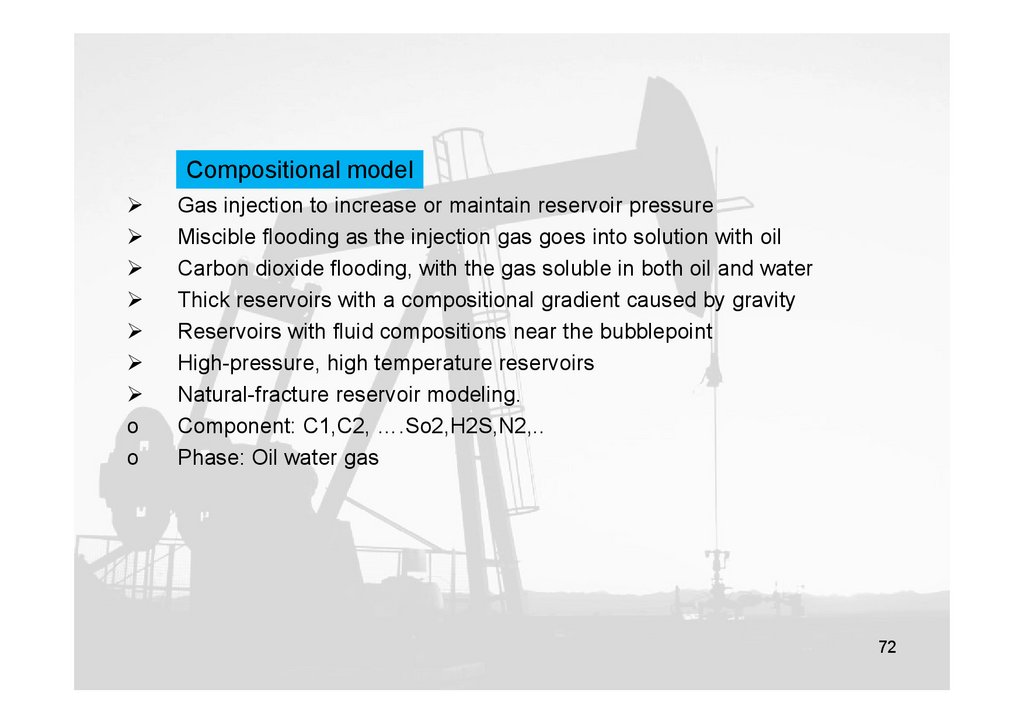
Compositional modelo
o
Gas injection to increase or maintain reservoir pressure
Miscible flooding as the injection gas goes into solution with oil
Carbon dioxide flooding, with the gas soluble in both oil and water
Thick reservoirs with a compositional gradient caused by gravity
Reservoirs with fluid compositions near the bubblepoint
High-pressure, high temperature reservoirs
Natural-fracture reservoir modeling.
Component: C1,C2, ….So2,H2S,N2,..
Phase: Oil water gas
72
73.
Chemical modelo
o
Polymer and surfactant injection
Component: Water oil surfactant alcohol
Phase: Agues oleic microemulsion
73
74.
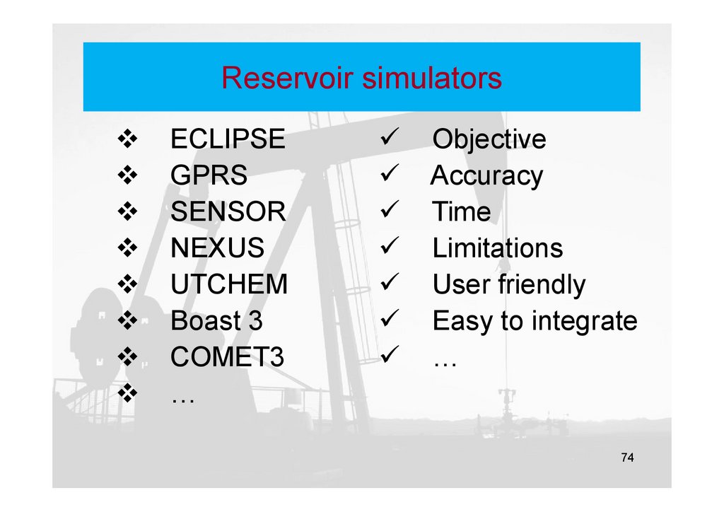
Reservoir simulatorsECLIPSE
GPRS
SENSOR
NEXUS
UTCHEM
Boast 3
COMET3
…
Objective
Accuracy
Time
Limitations
User friendly
Easy to integrate
…
74
75.
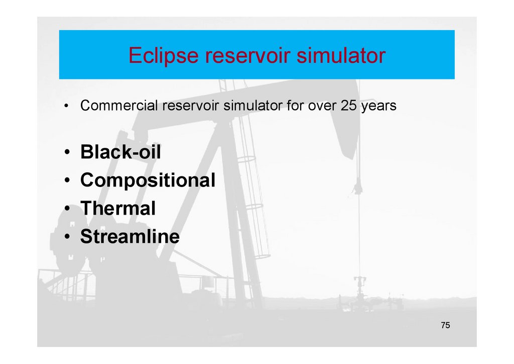
Eclipse reservoir simulator• Commercial reservoir simulator for over 25 years
• Black-oil
• Compositional
• Thermal
• Streamline
75
76.
Eclipse reservoir simulatorLocal Grid Refinement
Gas Lift Optimization
Gas Field Operations
Gas Calorific Value-Based
Control
Geomechanics
Coalbed Methane
Networks
Reservoir Coupling
Flux Boundary
Environmental Traces
Open-ECLIPSE Developer's Kit
Pseudo-Compositional
EOR Foam
EOR Polymer
EOR Solvent
EOR Surfactant
Wellbore Friction
Multisegmented Wells
Unencoded Gradients
Parallel ECLIPSE
76
77.
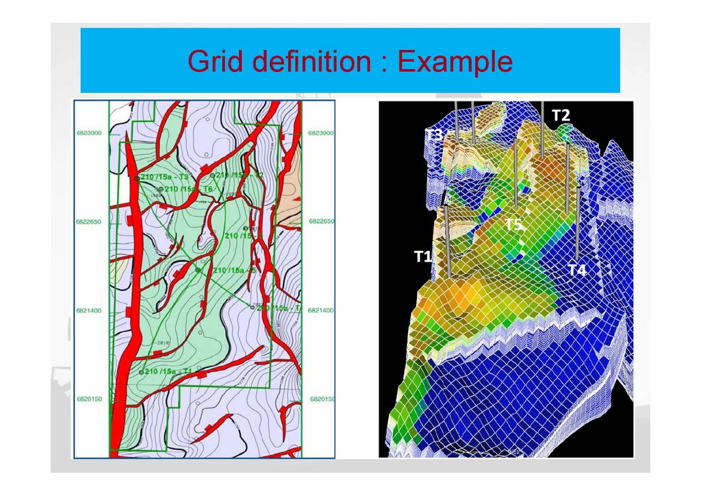
Grid definition : Example77
78.
Rock properties: Main parameters78
79.
Thank You!79