

 Электроника
Похожие презентации:


CV9632H-A50-14 maintenance guide
1.
CV9632H-A50Common problems solution
—Power Units Problem Solving
—Display Units Problem Solving
—Audio Units Problem Solving
—Functional Units Problem Solving
2.
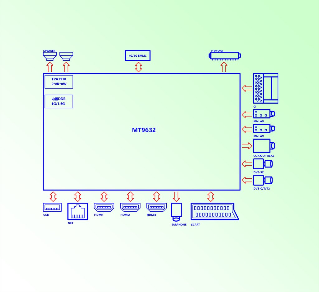
SPEAKERV By One
4G/8G EMMC
TPA3138
2*8R*8W
内置DDR
1G/1.5G
CI
MNI AV
MT9632
MNI AV
COAX/OPTICAL
DVB-S2
DVB-C/T/T2
USB
HDMI1
NET
HDMI2
HDMI3
EARPHONE
SCART
3.
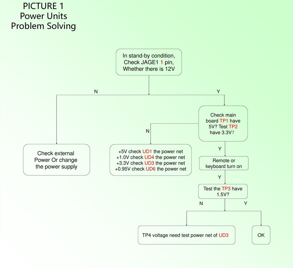
PICTURE 1Power Units
Problem Solving
In stand-by condition,
Check JAGE1 1 pin,
Whether there is 12V
N
Y
Check main
board TP1 have
5V? Test TP2
have 3.3V
N
Check external
Power Or change
the power supply
Y
+5V check UD1 the power net
+1.0V check UD4 the power net
+3.3V check UD3 the power net
+0.95V check UD6 the power net
Remote or
keyboard turn on
Y
Test the TP3 have
1.5V?
N
TP4 voltage need test power net of UD3
Y
OK
4.
PICTURE 2Display Unit
(black screen)
Flickering or
Black screen
Back light on
Check the connection
of Driver Board
Cable connect well
N
Change the LCD,
check if it is ok
Y
N
Check the network output,
Check JV1
45-51 pin have output
N
Y
Change the circuit
N
Check the software
match able
Y
Change
LCD
Check U1
Power supply and clock
circuit chip LVDS output
pin is short circuit,
or open-circuit
N
RE-Upgrade
software
Check LCD power
VCC-Panel is OK
Change driver
board cable
5.
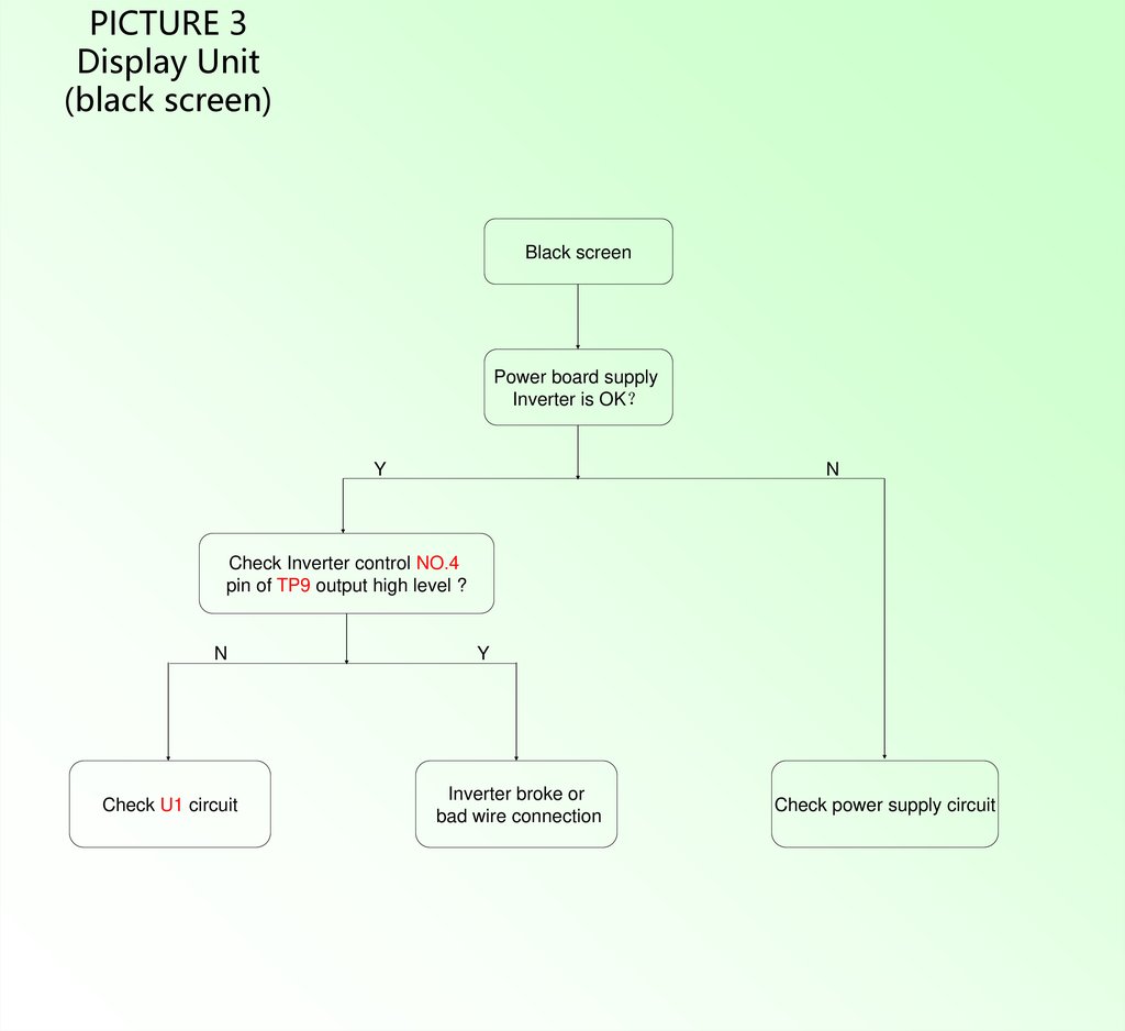
PICTURE 3Display Unit
(black screen)
Black screen
Power board supply
Inverter is OK
Y
N
Check Inverter control NO.4
pin of TP9 output high level ?
N
Check U1 circuit
Y
Inverter broke or
bad wire connection
Check power supply circuit
6.
PICTURE 4Audio Unit
(no sound)
No sound
If Any audio signal input or
amplifier power supply normal
Y
N
Check the Volume,
MUTE settings
N
Y
JA1 if
any signal output
Y
N
NO.4 and NO.12
pin of UA4 have
signal input
Y
Repair amplifier circuit power
If power supply works well
test electrolytic capacitor
or change UA1
Test U1 audio input
pin have single in
Y
Check
External audio
equipment
Amplifier power
supply circuit
Reset
Check
external
Speaker
Repair U1 to UA1
middle part net
N
Check main chip audio
input single is normal
7.
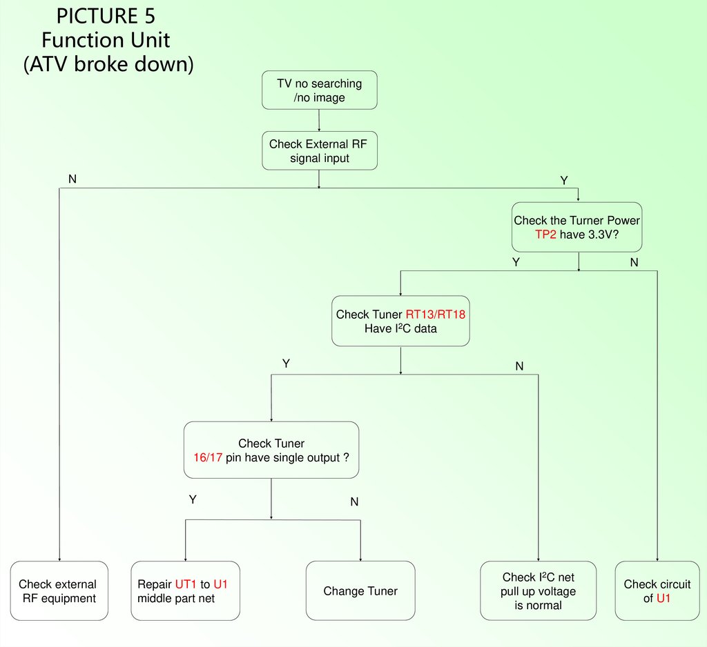
PICTURE 5Function Unit
(ATV broke down)
TV no searching
/no image
Check External RF
signal input
N
Y
Check the Turner Power
TP2 have 3.3V?
Y
N
Check Tuner RT13/RT18
Have I2C data
Y
N
Check Tuner
16/17 pin have single output ?
Y
Check external
RF equipment
Repair UT1 to U1
middle part net
N
Change Tuner
Check I2C net
pull up voltage
is normal
Check circuit
of U1
8.
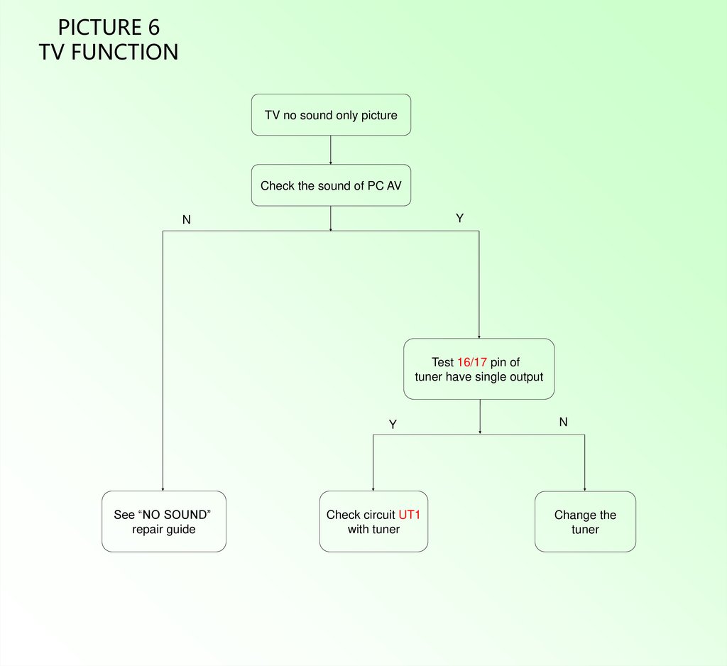
PICTURE 6TV FUNCTION
TV no sound only picture
Check the sound of PC AV
Y
N
Test 16/17 pin of
tuner have single output
Y
See “NO SOUND”
repair guide
Check circuit UT1
with tuner
N
Change the
tuner
9.
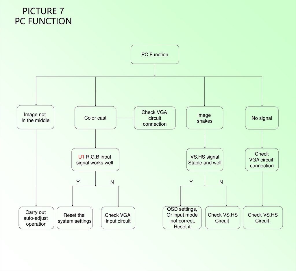
PICTURE 7PC FUNCTION
PC Function
Image not
In the middle
Check VGA
circuit
connection
Color cast
U1 R.G.B input
signal works well
Y
Carry out
auto-adjust
operation
Reset the
system settings
N
Check VGA
input circuit
Image
shakes
No signal
VS,HS signal
Stable and well
Check
VGA circuit
connection
Y
OSD settings,
Or input mode
not correct,
Reset it
N
Check VS.HS
Circuit
Check VS.HS
Circuit
10.
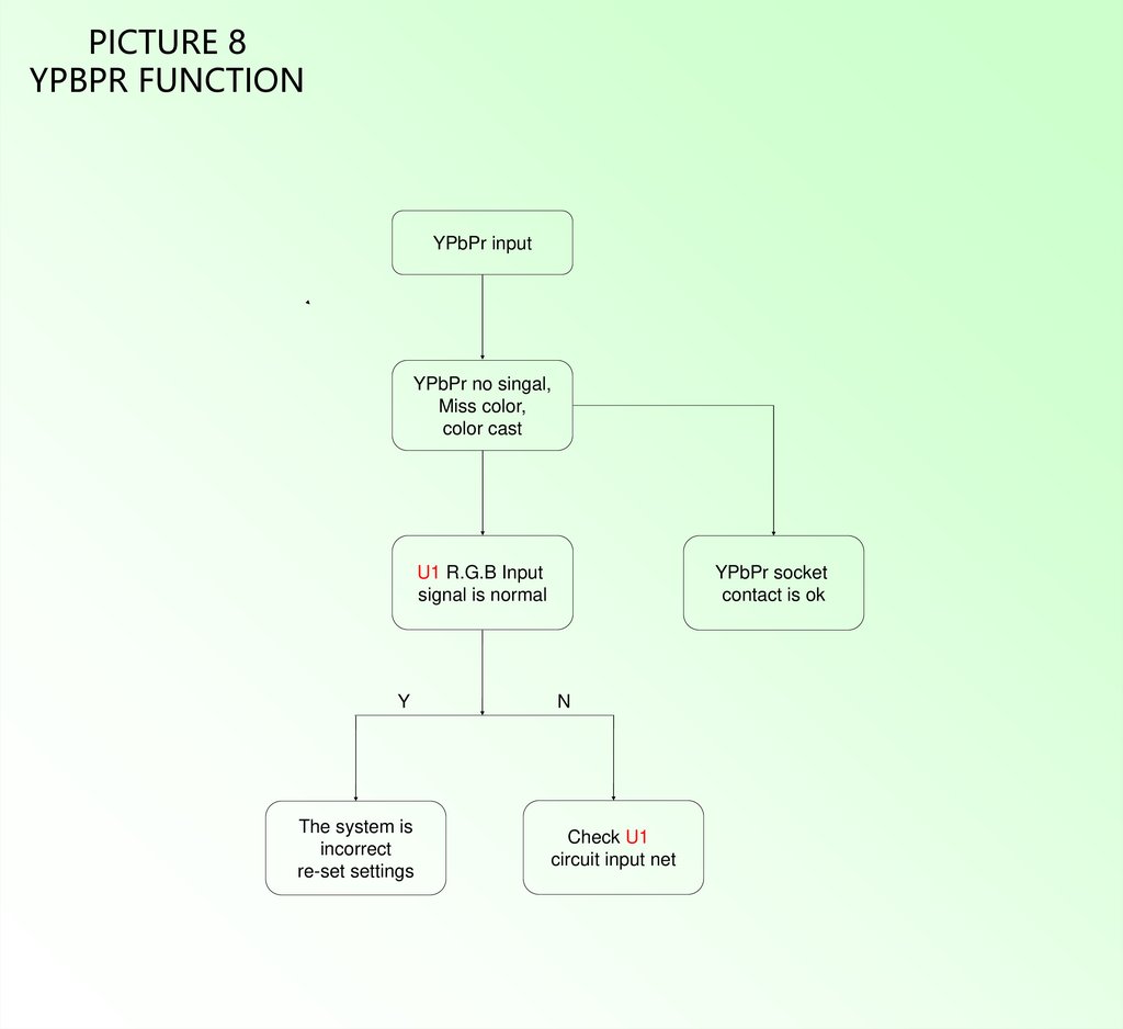
PICTURE 8YPBPR FUNCTION
YPbPr input
YPbPr no singal,
Miss color,
color cast
U1 R.G.B Input
signal is normal
Y
The system is
incorrect
re-set settings
YPbPr socket
contact is ok
N
Check U1
circuit input net
11.
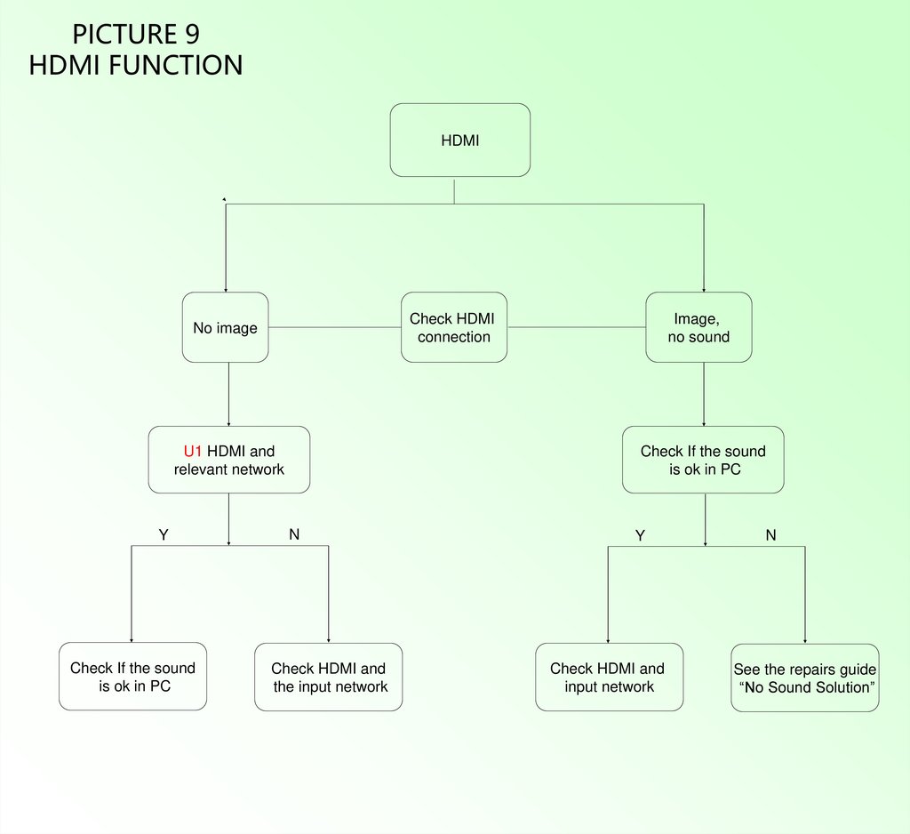
PICTURE 9HDMI FUNCTION
HDMI
Check HDMI
connection
No image
U1 HDMI and
relevant network
Y
Check If the sound
is ok in PC
Image,
no sound
Check If the sound
is ok in PC
N
Check HDMI and
the input network
Y
Check HDMI and
input network
N
See the repairs guide
“No Sound Solution”
12.
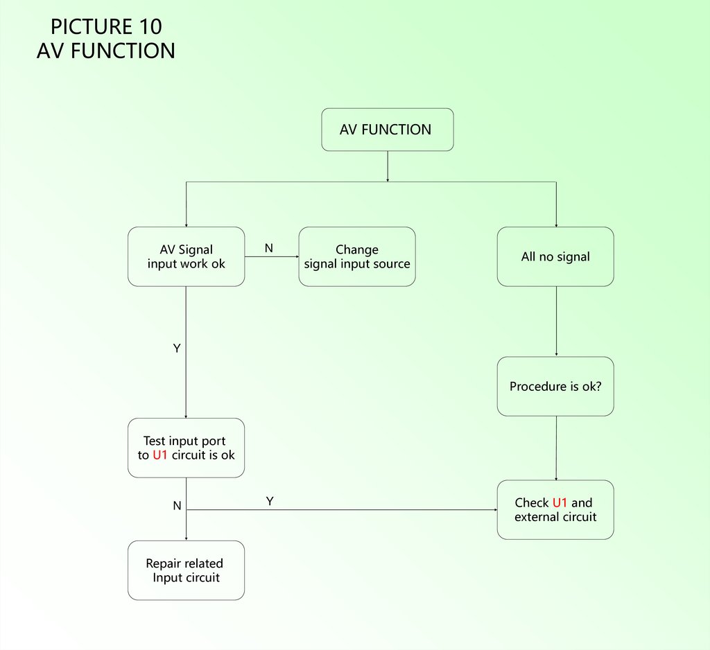
PICTURE 10AV FUNCTION
AV FUNCTION
AV Signal
input work ok
N
Change
signal input source
All no signal
Y
Procedure is ok?
Test input port
to U1 circuit is ok
N
Repair related
Input circuit
Y
Check U1 and
external circuit