


 Электроника
Похожие презентации:


")
CV338H-U42-10 maintainance guide
1.
CV338H-U42Common problems solution
—Power Unit Problem Solving
—Display Unit Problem Solving
—Audio Unit Problem Solving
—Functional Unit Problem Solving
2.
SYSTEM BLOCKLVDS
EMMC FLASH
4GB
RDA3118e
USB2.0*2
DDR3 -2133M
MSD6A338
RCA_YPBPRIN
PCMCIA
Embedded
YPBPRIN AVIN
32M X 16 / 512MB
VGA
PC_Audio_in
ATV&DVBT
HDMI1
EarPhone
RJ45
AVIN
SCART/RCA_AVIN
HDMI2
HDMI3(ARC)
Coax/Optical
3.
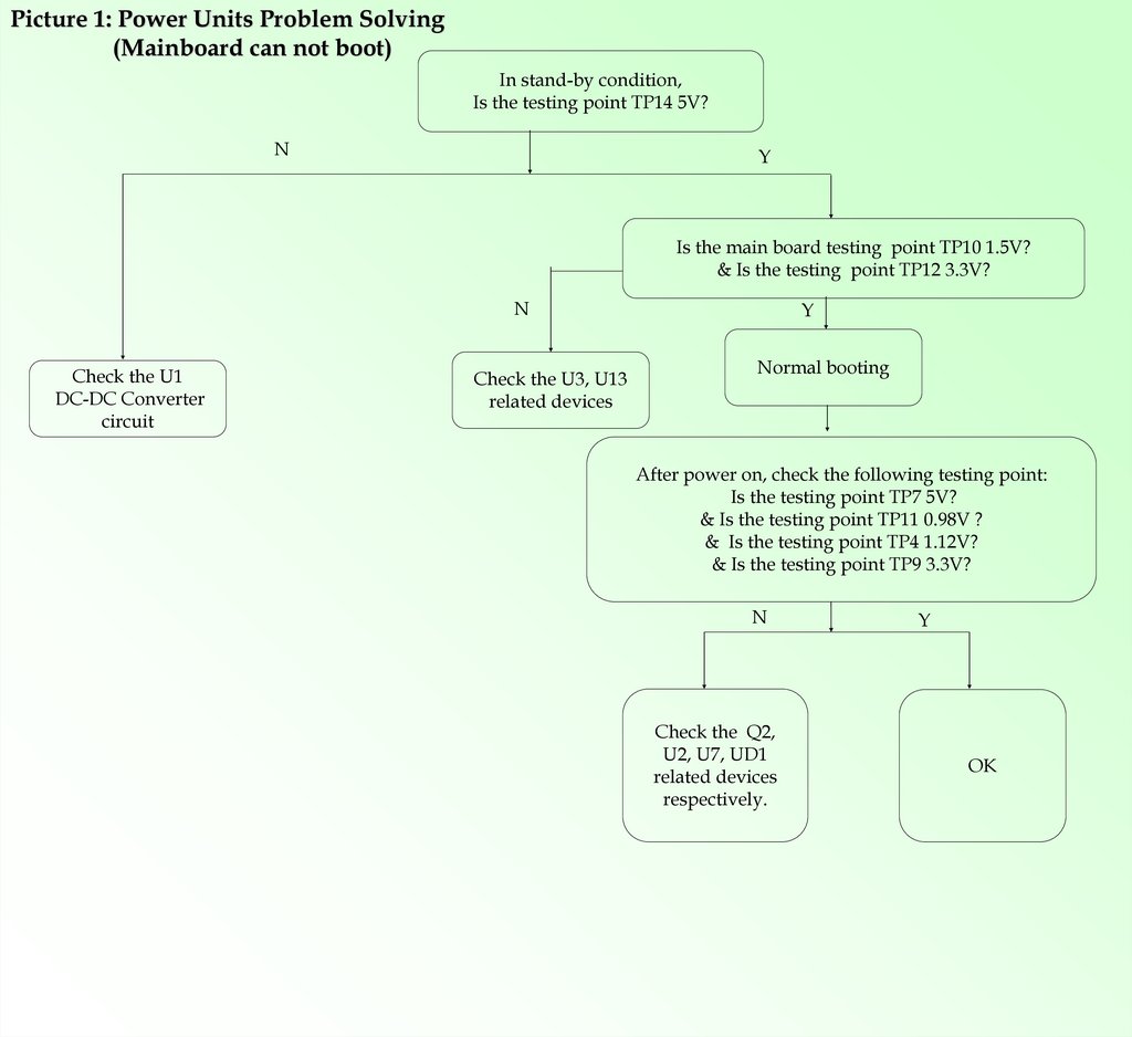
Picture 1: Power Units Problem Solving(Mainboard can not boot)
In stand-by condition,
Is the testing point TP14 5V?
N
Y
Is the main board testing point TP10 1.5V?
& Is the testing point TP12 3.3V?
N
Check the U1
DC-DC Converter
circuit
Check the U3, U13
related devices
Y
Normal booting
After power on, check the following testing point:
Is the testing point TP7 5V?
& Is the testing point TP11 0.98V ?
& Is the testing point TP4 1.12V?
& Is the testing point TP9 3.3V?
N
Check the Q2,
U2, U7, UD1
related devices
respectively.
Y
OK
4.
Picture 2Display unit ( black screen)
Black screen
Is the testing point TP8 12V?
Y
N
Is the alignment of LVDS cable correct?
Does the LVDS socket welded correctly?
Are the LVDS signals normal?
Are the lines from CPU to LVDS intact?
N
Y
Does the main chip welded
correctly?
Is the screen OK?
N
The main chip(CPU)
is damaged.
Inverter is broken or
connecting line is not good.
Is the status of switching MOSFET
Q4 on?
Is the control signal PANEL_ON/OFF
high?
Check the 12V supply voltage, being
short-circuited?
5.
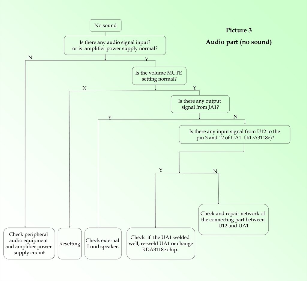
No soundPicture 3
Audio part (no sound)
Is there any audio signal input?
or is amplifier power supply normal?
N
Y
Is the volume MUTE
setting normal?
Y
N
Is there any output
signal from JA1?
N
Y
Is there any input signal from U12 to the
pin 3 and 12 of UA1 RDA3118e)?
Y
N
Check and repair network of
the connecting part between
U12 and UA1
Check peripheral
audio equipment
and amplifier power
supply circuit
Resetting
Check external
Loud speaker.
Check if the UA1 welded
well, re-weld UA1 or change
RDA3118e chip.
6.
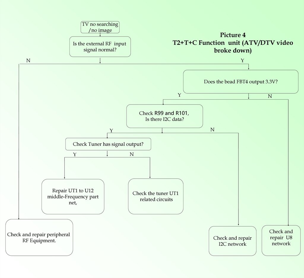
TV no searching/no image
Picture 4
T2+T+C Function unit (ATV/DTV video
broke down)
Is the external RF input
signal normal?
N
Y
Does the bead FBT4 output 3.3V?
Y
N
Check R99 and R101,
Is there I2C data?
N
Y
Check Tuner has signal output?
Y
Repair UT1 to U12
middle-Frequency part
net,
Check and repair peripheral
RF Equipment.
N
Check the tuner UT1
related circuits
Check and repair
I2C network
Check and
repair U8
network
7.
Picture 5TV no sound, only picture
Function unit (ATV/DTV no
sound)
Whether there is
sound under PC AV
N
Y
Whether software is
OK? input system is
set correctly?
Y
Refer to “NO SOUND”
repair guide
Change U12
8.
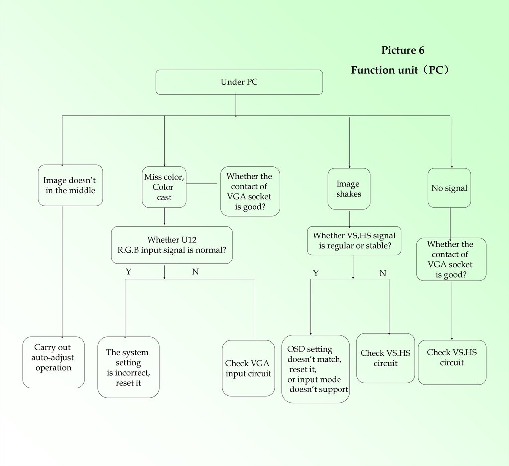
Picture 6Function unit PC
Under PC
Whether the
contact of
VGA socket
is good?
Miss color,
Color
cast
Image doesn’t
in the middle
Whether U12
R.G.B input signal is normal?
Y
Carry out
auto-adjust
operation
The system
setting
is incorrect,
reset it
N
Image
shakes
Whether VS,HS signal
is regular or stable?
Y
Check VGA
input circuit
No signal
OSD setting
doesn’t match,
reset it,
or input mode
doesn’t support
N
Check VS.HS
circuit
Whether the
contact of
VGA socket
is good?
Check VS.HS
circuit
9.
Picture 7Function unit HDMI
Under HDMI
No image
There is image
but no sound
Are HDMI
signals intact?
Is the HOTPLUG
pin high?
Is there any
sound under PC?
Y
Is HDMI related network
to U12 good?
Y
Change the software and
Re-weld the U12 and
HDMI connecter
Y
N
Check HDMI
input network
and EDID
Refer to "no
sound" repair
guide
N
Check HDMI
and input
network