


 Электроника
Похожие презентации:


")


CV3663BH-Q32. Common problems solution
1.
CV3663BH-Q32Common problems solution
—Power Unit Problem Solving
—Display Unit Problem Solving
—Audio Unit Problem Solving
—Functional Unit Problem Solving
2.
3.
Picture 1: Power Units Problem Solving(Mainboard can not boot)
In stand-by condition,
Check pin 5,6 of TP20,
Whether got 12V
N
Y
Whether main board testing point TP24 got 5V?
testing C25 got 3.3v?
N
Check AC power
supply circuit
Y
Normal booting
Check the U1, U4
related devices
After power on, check
whether testing point TP13
got 3.3v,testing point TP4
got 1.5v ,testing point TP22
got 1.1v?
N
Whether power chip (U25,U13,U3)
works?
Y
OK
4.
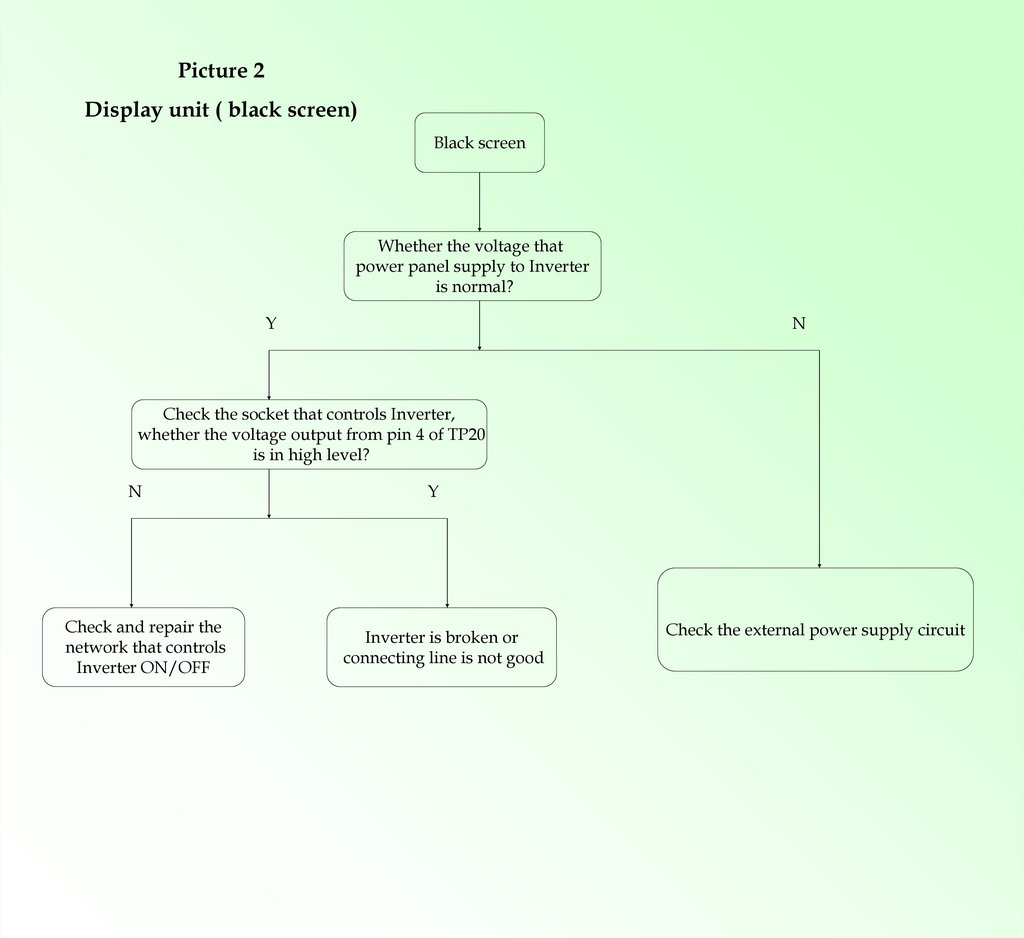
Picture 2Display unit ( black screen)
Black screen
Whether the voltage that
power panel supply to Inverter
is normal?
Y
N
Check the socket that controls Inverter,
whether the voltage output from pin 4 of TP20
is in high level?
N
Check and repair the
network that controls
Inverter ON/OFF
Y
Inverter is broken or
connecting line is not good
Check the external power supply circuit
5.
No soundPicture 3
If there is any audio signal input
or Whether amplifier power supply
is normal?
N
Audio part (no sound)
Y
Whether the volume,
MUTE
setting is normal?
N
Y
Whether there is
signal output from J24?
N
Y
Whether there is signal
input in
U10 AD5205D pin 3/12 ?
Y
Check
peripheral
audio
equipment:
amplifier
power
supply
circuit
Check
Resetting
external
loudspeaker
Check if the U201 welded
Well , re-weld U10 or change
AD5205D chip.
N
Check and repair
network
of the connecting
part between
U201 and U10
6.
TV no searching/no image
Picture 4
T2+T+C Function unit (ATV/DTV video
broke down)
Check whether
external RF input signal
is normal?
N
Y
Whether main board testing TP13 output 3.3V?
Y
N
Check R322,R323,
whether there is I2C data?
N
Y
Check Tuner have single output?
Y
Repair U12 to
U201 middleFrequency part
net,
Check and
repair
peripheral
RF
equipment
N
Check the
tuner U12
related circuits
Check and repair
I2C network
Check and
repair U25
network
7.
TV no searching/no image
Picture 5
S2 Function unit (DTV video broke
down)
Check whether
external RF input signal
is normal?
N
Y
Whether main board testing FB13 output 3.3V?
Y
N
Check R237,R238,
whether there is I2C data?
N
Y
Check Tuner have single output?
Y
Repair U15t o
U201 middleFrequency part
net,
Check and
repair
peripheral
RF
equipment
N
Check the
tuner U15
related circuits
Check and repair
I2C network
Check and
repair U25
network
8.
Picture 6TV no sound, only picture
Function unit (ATV/DTV no
sound)
Whether there is
sound under PC AV
N
Y
Whether software is
OK? input system is
set correctly?
Y
Refer to “NO SOUND”
repair guide
Change U201
9.
Picture 7Function unit PC
Under PC
Whether the
contact of
VGA socket
is good?
Miss color,
Color
cast
Image not
in the middle
Whether U201
R.G.B input signal is normal?
Y
Carry out
auto-adjust
operation
The system
setting
is incorrect,
reset it
N
Image
shakes
Whether VS,HS signal
is regular or stable?
Y
Check VGA
input circuit
No signal
OSD setting
doesn’t match,
reset it,
or input mode
doesn’t support
N
Check VS.HS
circuit
Whether the
contact of
VGA socket
is good?
Check VS.HS
circuit
10.
Picture 8Function unit HDMI
Under HDMI
There is image
but no sound
Whether HDMI
contact
is good?
No image
Check whether
HOTPLUG pin is
high?
Whether there is
sound under PC?
Y
Check HDMI related
network of U201
Y
Change the software and
Re-weld the U201&HDMI
connecter
Y
N
Check HDMI
input network
and EDID
Refer to "no
sound" repair
guide
N
Check HDMI
and input
network