


")


 Электроника
Похожие презентации:


 Application in Smart Grids")
Current and voltage transformers
1. Включение
Current and voltage transformersВключение
2.
• Измерительные трансформаторы тока инапряжения применяют в качестве
преобразователей больших переменных
токов и напряжений в относительно малые
величины, измерение которых возможно
стандартными приборами с относительно
небольшими пределами измерений.
3.
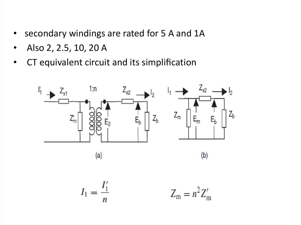
• secondary windings are rated for 5 A and 1A• Also 2, 2.5, 10, 20 A
• CT equivalent circuit and its simpli cation
4.
• the leakage impedance of the primary windingZx1 has no effect on the performance of the
transformer, and may be omitted.
• The load impedance Zb includes the
impedance of all the relays and meters
connected in the secondary winding
5.
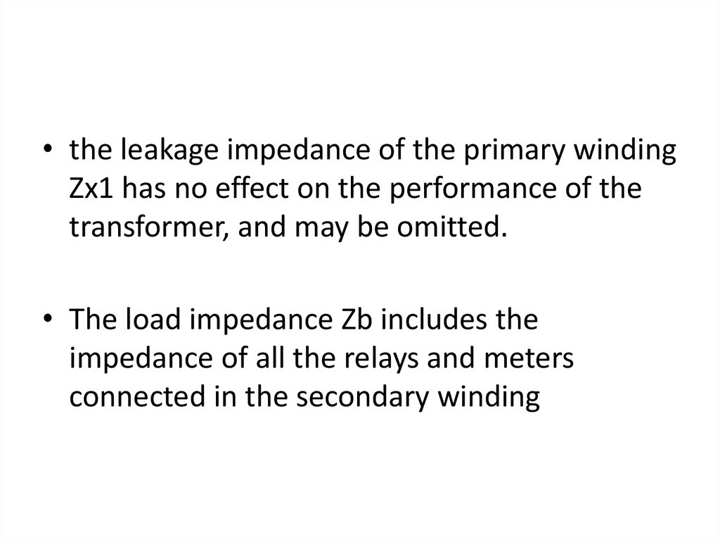
• CT phasor diagram• the voltage Em across the magnetizing impedance Zm is given
by
Em = Eb +Zx2I2
• The magnetizing current Im is given by
Im =Em/ Zm
• The primary current I1 (referred to the secondary winding) is
given by
I1 = I2 +Im
6.
• The per unit current transformation errorde ned by
• The ratio correction factor R is de ned as the
constant by which the name plate turns ratio
n of a current transformer must be multiplied
to obtain the effective turns ratio
• Although ∈ and R are complex numbers
7. Example
• Consider a current transformer with a turnsratio of 500 : 5, a secondary leakage
impedance of (0.01+j0.1) and a resistive
burden of 2.0 . If the magnetizing impedance
is (4.0+j15) , then for a primary current
(referred to the secondary) of Il, find the error
and the correction factor.
8.
• Since the magnetizing branch of a practical transformer isnonlinear, Zm is not constant, and the actual excitation
characteristic of the transformer must be taken into account
in determining the factor R for a given situation.
9.
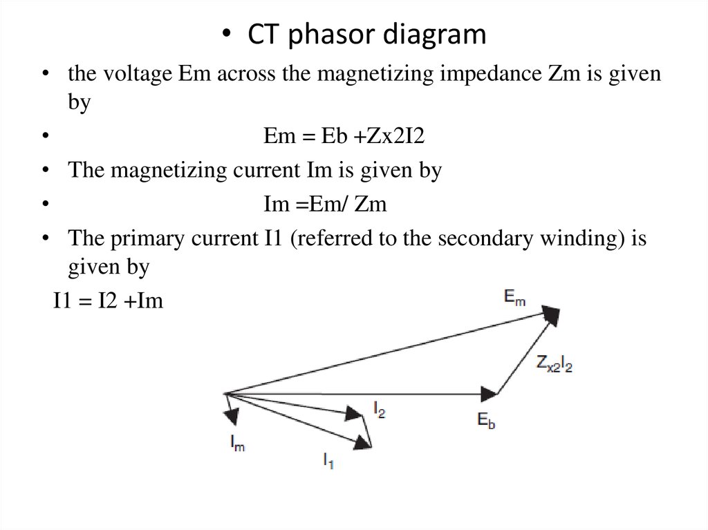
• The magnetizing characteristic of a typical CT is shown in thisFigure
• This being a plot of the r.m.s. magnetizing current versus the
r.m.s. secondary voltage, Im for each Em must be obtained
from this curve, and then used in equations to calculate the
ratio correction factor
10. Из анализа полученных уравнений можно сделать следующие выводы:
• При возрастании сопротивления вторичной обмотки илиее разрыве (I2=0) происходит возрастание МДС Imw1 до
I1W1, это в свою очередь вызывает резкое увеличение
потока Фm, сопровождающееся
а) ростом потерь в сердечнике и его перегрев,
б)ростом ЭДС Е2, что может вызвать аварийную ситуацию
пробоя
• Увеличение сопротивления нагрузки вторичной цепи,
например, за счет включения большого числа приборов,
приводит к росту Im и тем самым к росту токовой и
угловой погрешностей. Im будет тем меньше, чем выше
магнитная проницаемость сердечника и чем меньше
магнитные потери, а также при уменьшении индукции до
~0,05-0,15 Тл
• Увеличение индуктивного сопротивления нагрузки
приводит к увеличению угла и следовательно к
увеличению токовой погрешности и уменьшению угловой
погрешности.
11. Polarity markings on CT windings
• ExampleConsider the CTs shown in Figures (a) and (b) If the primary
current is 1000 A, and the two CT ratios are 1000 : 5 and 1000 :
5 respectively, the current in the burden impedance ZL is 10 A
Figure (a)
• If the CT secondaries are connected as shown in Figure (b), the
burden current becomes zero.
12.
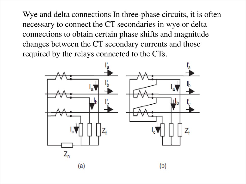
Wye and delta connections In three-phase circuits, it is oftennecessary to connect the CT secondaries in wye or delta
connections to obtain certain phase shifts and magnitude
changes between the CT secondary currents and those
required by the relays connected to the CTs.
13.
• Consider the CT connections shown in Figure The wyeconnection shown in Figure (a) produces currents
proportional to phase currents in the phase burdens Zf and
a current proportional to 3Io in the neutral burden Zn. No
phase shifts are introduced by this connection.
• The delta connection shown in Figure (b) produces
currents proportional to (Ia −Ib), (Ib −Ic) and ( Ic −Ia)
in the three burdens Zf. If the primary currents are
balanced, (Ia −Ib) =√3|Ia|exp(jπ/6), and a phase shift
of 30◦ is introduced between the primary currents and
the currents supplied to the burdens Zf. By reversing
the direction of the delta windings, a phase shift of
−30◦ can be obtained.
14. Principle of the magneto-optic current transformer (MOCT)
Most of the practical electronic CTs are based upon the relationship betweenthe magnetizing eld produced by a current-carrying conductor and the plane
of polarization of polarized light passing through a ber-optic block placed
around the conductor. In some designs, a ber-optic cable goes around the
conductor (making several turns as necessary). The angle through which the
plane of polarization of the light rotates is detected at the receiving end
15.
• This angular shift is electronically converted to a voltage,which is proportional to the instantaneous value of the
magnetizing force around the current-carrying conductor, and
hence to the instantaneous value of the current. This voltage
may then be suitably ampli ed and ltered to provide a replica
of the current in the primary conductor. Alternatively, the
voltage may be sampled at a suitable rate to provide a
sampled-data representation of the primary current. It should
be clear that such an electronic CT is most suited to relays and
meters which can utilize low-power signals, or sampled data of
the signals. As will be seen later, this type of signal source is
particularly suited for electronic relays and computer relays.
Electronic CTs are linear, and have a very wide dynamic
range, i.e. they are able to measure accurately currents at light
loads as well as those corresponding to very heavy faults.
16. Voltage transformers
• Voltage transformers – also known as potential transformers –are normal transformers with the primary winding connected
directly to the high-voltage apparatus, and with one or more
secondary windings rated at the standard voltage of 69.3 V for
phase-to-neutral voltages or 120 V for phase to-phase voltages.
• Their performance, equivalent circuit and phasor diagrams are
similar to those of a power transformer. The error of
transformation of such a transformer is negligible for all
practical purposes in its entire operating range – from zero to
about 110% of its normal rating. We may consider such
transformers to be error-free from the point of view of
relaying. Voltage transformers are rather expensive, especially
at extra high voltages: 345 kV or above. Consequently, they
are usually found on low-, medium- and high-voltage systems.
At extra high voltages, capacitive
17.
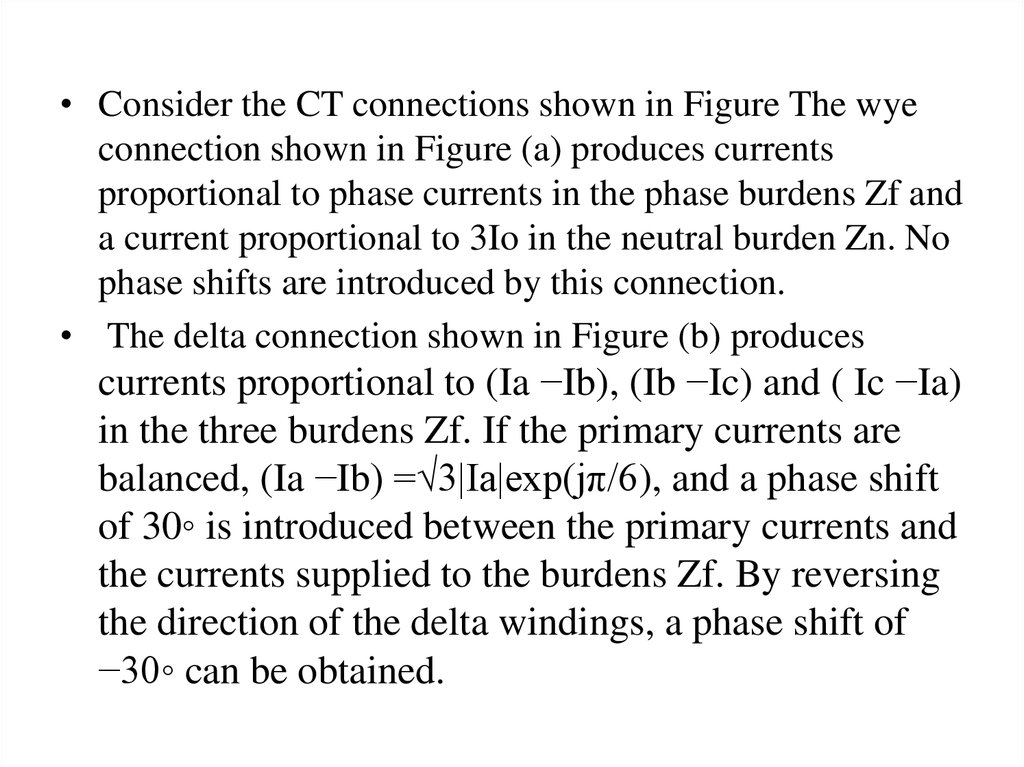
• Are the more usual sources for relaying and metering.• In passing, we may mention a possible problem with voltage
transformers when used on ungrounded (or high-impedance
grounded) power systems. As shown in the Figure,
when a ground fault occurs on such
a system, the voltage transformers
connected to the unfaulted phases
are subjected to a voltage equal to
the phase-to-phase voltage of the
power system. This usually drives
one of the transformers well into
saturation, and, because of the
excessive magnetizing current
drawn by this transformer, may
blow the protective fuse.
18. Coupling capacitor voltage transformers CCVT Connections and equivalent circuit
19.
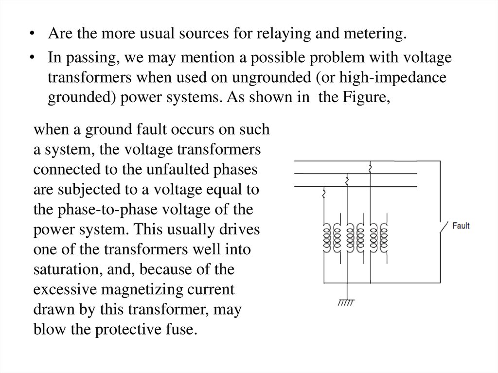
• The Thevenin voltage is given by• and the Thevenin source impedance is a capacitance of
(C1 +C2)
• Since the Thevenin impedance of a CCVT is capacitive, the
nonlinear magnetizing branch of the connected transformer
may give rise to Ferro resonant oscillations, especially under
light loads.
• Zf, is usually provided to damp these oscillations.