

 Механика
Похожие презентации:


 Application Model")
AutoFold Plus. Possible subtitle of the presentation
1.
AutoFold PlusPossible subtitle of the presentation
Name and title
City, Country
15-10-2013
Contains confidential proprietary and trade secrets information of CNH Industrial. Any use of this work without express written consent is strictly prohibited.
2.
AutoFold PlusCAN based system
Single Control Switch
Theory: We have sensors on the boom fold pivots,
using voltage signal back from those sensors to
control fold in and out operation of the boom with
one switch. Nodes are also there that constantly
supplied high current power through hydraulic
harness.
15-10-13
Footer
2
3.
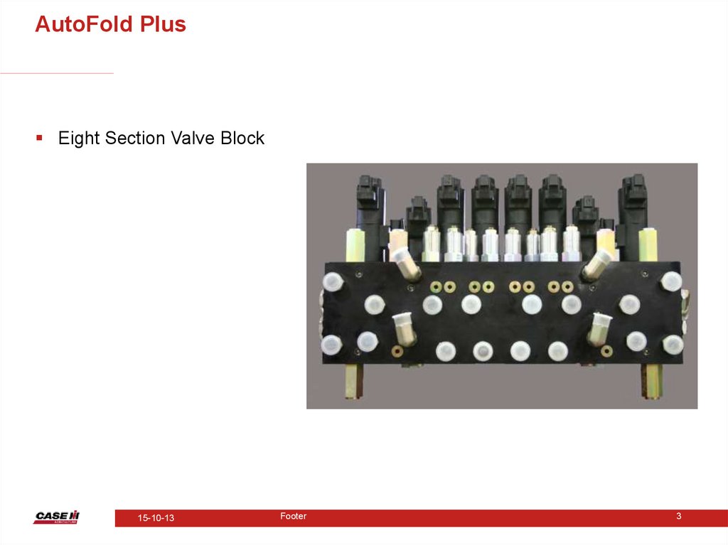
AutoFold PlusEight Section Valve Block
15-10-13
Footer
3
4.
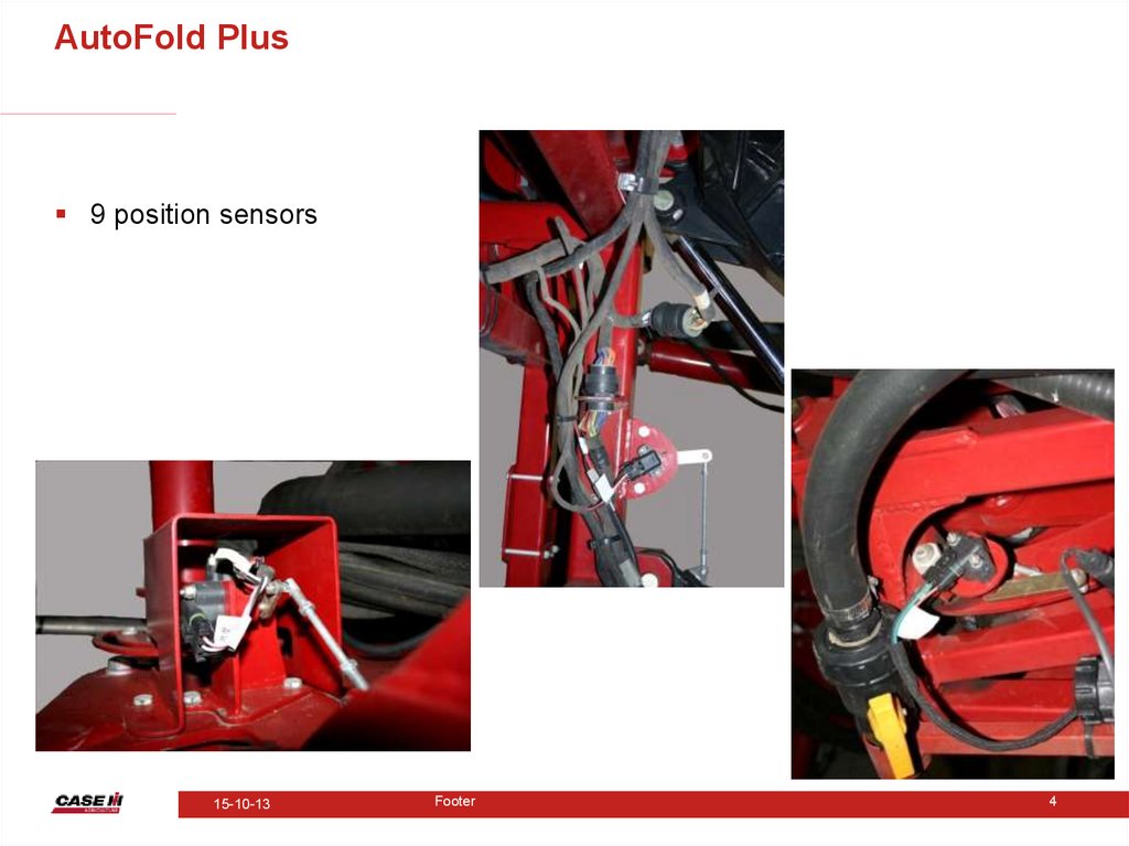
AutoFold Plus9 position sensors
15-10-13
Footer
4
5.
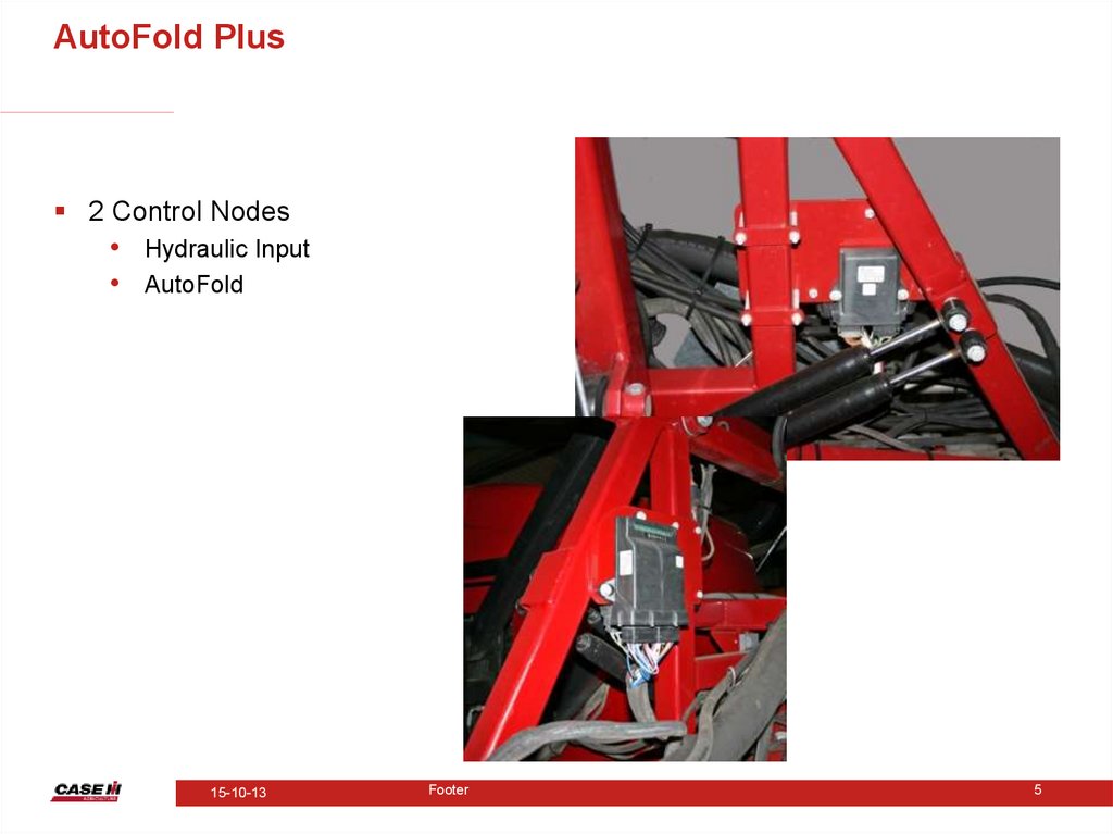
AutoFold Plus2 Control Nodes
• Hydraulic Input
• AutoFold
15-10-13
Footer
5
6.
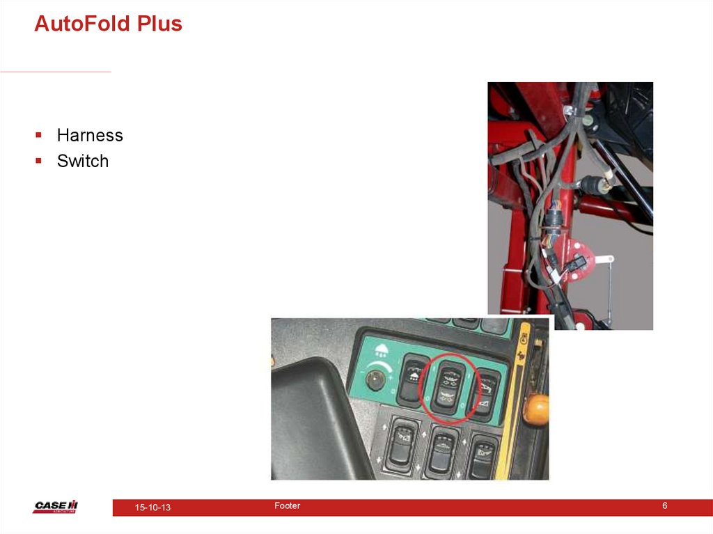
AutoFold PlusHarness
Switch
15-10-13
Footer
6
7.
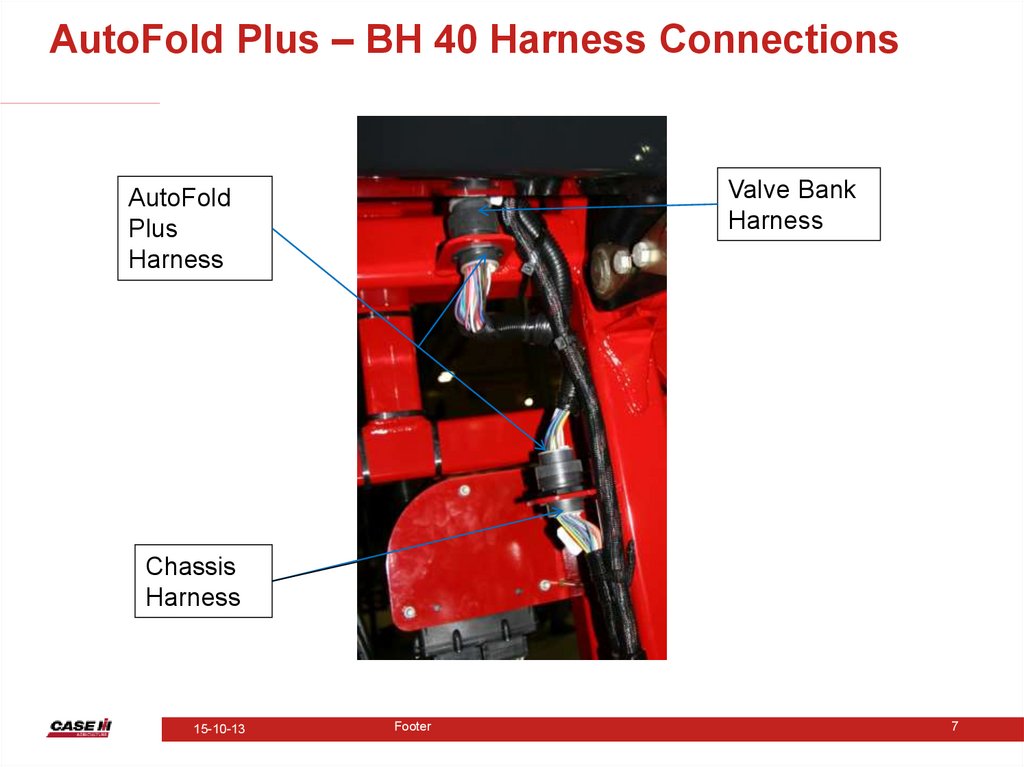
AutoFold Plus – BH 40 Harness ConnectionsValve Bank
Harness
AutoFold
Plus
Harness
Chassis
Harness
15-10-13
Footer
7
8.
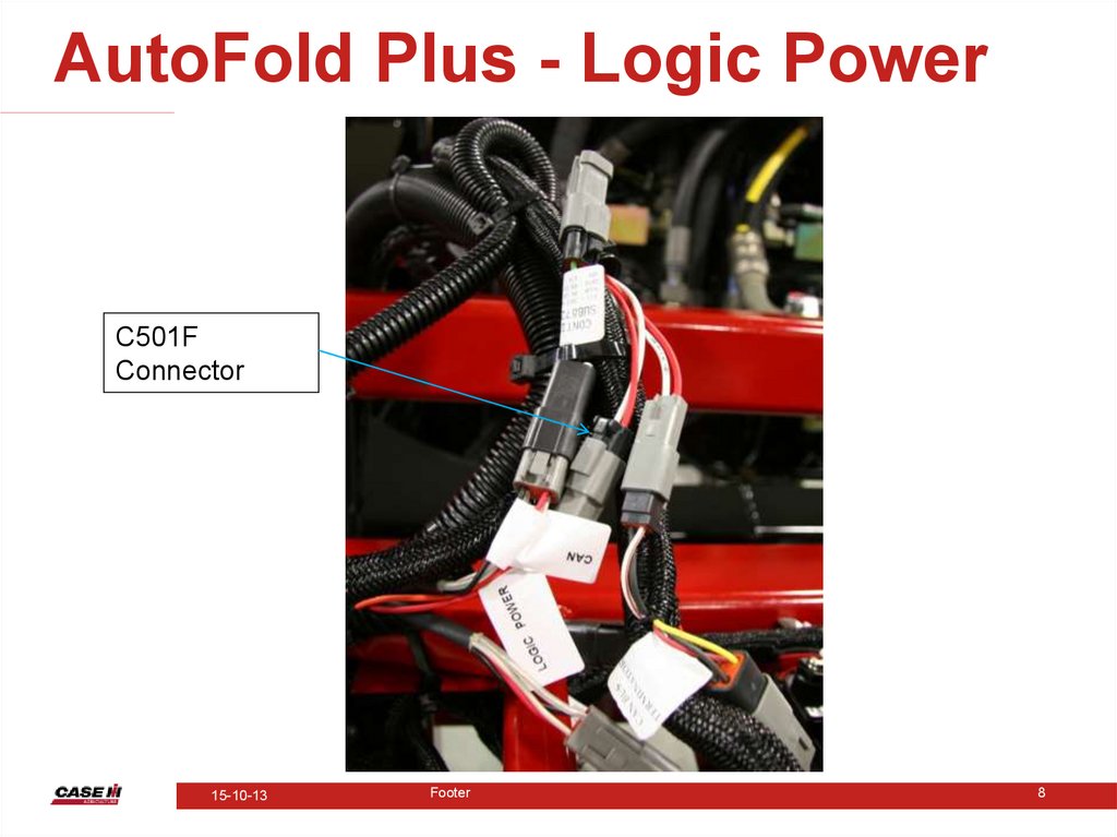
AutoFold Plus - Logic PowerC501F
Connector
15-10-13
Footer
8
9.
ProcessWhen the key switch is turned on power is supplied to pin 3 of RP6F and to pin 3 of BH 11.
Inside of the Raven controller harness the wire from pin 3 BH 11 is jumped to the wire going to pin 4 BH 11.
This wire passes back out on wire 758. Wire 758 passes power to pin 1 of RP6F switching the contacts and passing power out
pin 5 to the nodes. The key switch power is sent out through BH 5 pin 19 on the product control harness. On the product harness
there is a power splice pack SP757 located about four inches from Bulkhead 5, where the power is spliced out to the P501
connector near the end of this harness. This power and ground also supplies logic power to the AutoBoom node, if the machine is
so equipped.
Once the nodes are powered up, the AutoFold node sends a 5 volt signal out to each position sensor and reads the voltage signal
that is sent back. The voltage signals from each individual sensor should be very similar when the booms are completely folded in
or completely folded out. Once the Master Power switch is turned on, the AutoFold Plus system can be utilized. The rate
controller does not need to be powered in order to use AutoFold Plus. The controller does need to be powered to calibrate or
recalibrate the system, however.
When the AutoFold Plus switch is depressed to fold the booms in or out an electrical signal is passed to the Hydraulic Input node.
This node takes that signal and sends it over the CAN network to the AutoFold node, commanding the AutoFold node to begin
operation.
Once the AutoFold feature has been activated the AutoFold node sends a voltage signal out to each individual valve bank section
to control the folding of the various boom sections. It should be noted that six of the eight valves that control the boom folds are
PWM. These are the left and right fold inner, mid and outer fold in/out. The left and right boom level valves are regular valves.
Boom fold speed is controlled by varying the duty cycle to the six PWM valves.
Once the electrical signal sent back from the first boom section to fold in/out reaches a specified voltage the AutoFold node quits
applying voltage to that boom function valve and applies it to the next one in line and so on until the booms are completely folded
or unfolded.
The process in which the individual boom sections fold in or out is very similar whether they are coming in or going out. There is a
bit of difference, however. When folding out from the cradled position both inner booms raise up and start to swing back. When
the AutoFold node sees a specified voltage from the inner fold sensor the node will start to lower the right and left boom levels. At
the same time the mid folds will start to unfold. Once a specified voltage has been reached on the mid folds, the center will start to
lower and then the outers will fold out. When cradling the booms the center section will raise as the outers are folding in. From
here on out the process is the reverse of folding out. It should be noted that when the various folds reach a specified voltage the
fold/unfold speed will decrease so that the booms will not be damaged.
15-10-13
Footer
9
10.
AutoFold Plus – Position Sensors• Setup of Position sensors
– Once sensors are mounted correctly tie-rod
length needs to be set
– Tie-rod length varies depending on sensor
location
– Sensors in same position have the same
length, i.e. right outer and left outer
15-10-13
Footer
19
11.
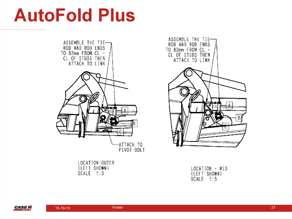
AutoFold Plus – Position Sensors• Outer and mid fold tie rod lengths
– 82 mm
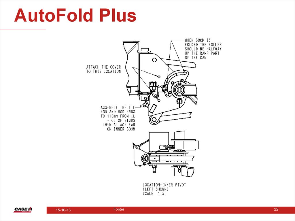
• Inner fold tie rod lengths
– 110 mm
• Boom level position sensor
– Roller positioned at 0.5 volts left and 4.5 volts
right
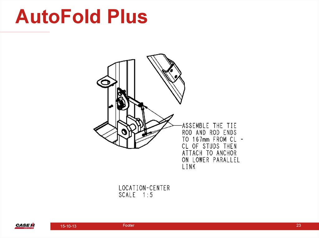
• Center section tie rod length
– 167 mm
15-10-13
Footer
20
12.
AutoFold Plus15-10-13
Footer
21
13.
AutoFold Plus15-10-13
Footer
22
14.
AutoFold Plus15-10-13
Footer
23
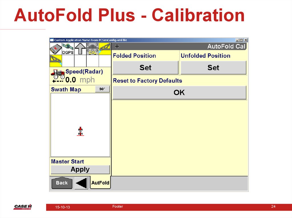
15.
AutoFold Plus - Calibration15-10-13
Footer
24
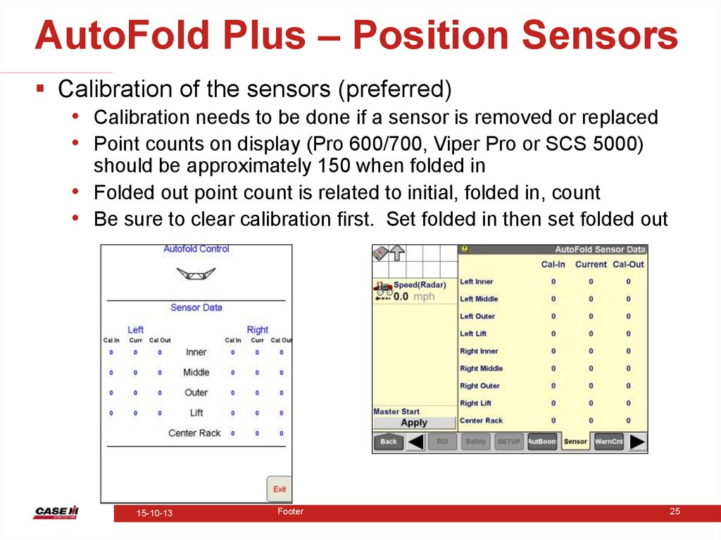
16.
AutoFold Plus – Position SensorsCalibration of the sensors (preferred)
• Calibration needs to be done if a sensor is removed or replaced
• Point counts on display (Pro 600/700, Viper Pro or SCS 5000)
should be approximately 150 when folded in
• Folded out point count is related to initial, folded in, count
• Be sure to clear calibration first. Set folded in then set folded out
15-10-13
Footer
25
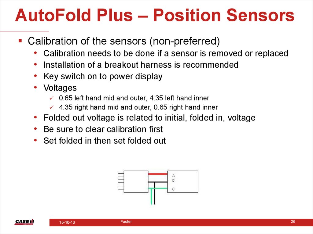
17.
AutoFold Plus – Position SensorsCalibration of the sensors (non-preferred)
• Calibration needs to be done if a sensor is removed or replaced
• Installation of a breakout harness is recommended
• Key switch on to power display
• Voltages
0.65 left hand mid and outer, 4.35 left hand inner
4.35 right hand mid and outer, 0.65 right hand inner
• Folded out voltage is related to initial, folded in, voltage
• Be sure to clear calibration first
• Set folded in then set folded out
15-10-13
Footer
26
18.
AutoFold Plus - Calibration• Controller Calibration
– Controller should come calibrated
– If controller needs to be recalibrated the default
settings must be reset
– Booms must be fully cradled and lightly sitting
in the cradles before starting calibration
15-10-13
Footer
27
19.
AutoFold Plus• The AutoFold node sends power, ground
and signal to the position sensors.
• The AutoFold node determines where the
booms are positioned and which boom fold
function needs to occur next.
• A PWM signal is sent out the valves on the
valve block to actuate.
• As the desired boom fold is nearing
completion the PWM signal decreases
slowing down the boom fold.
15-10-13
Footer
28
20.
AutoFold Plus - Troubleshooting• Troubleshooting
– A component failure will generate a warning
message
Either using AutoFold Plus or individual boom
function
– Use Sensor Data Screen to view point counts
to determine cause of failure
15-10-13
Footer
30
21.
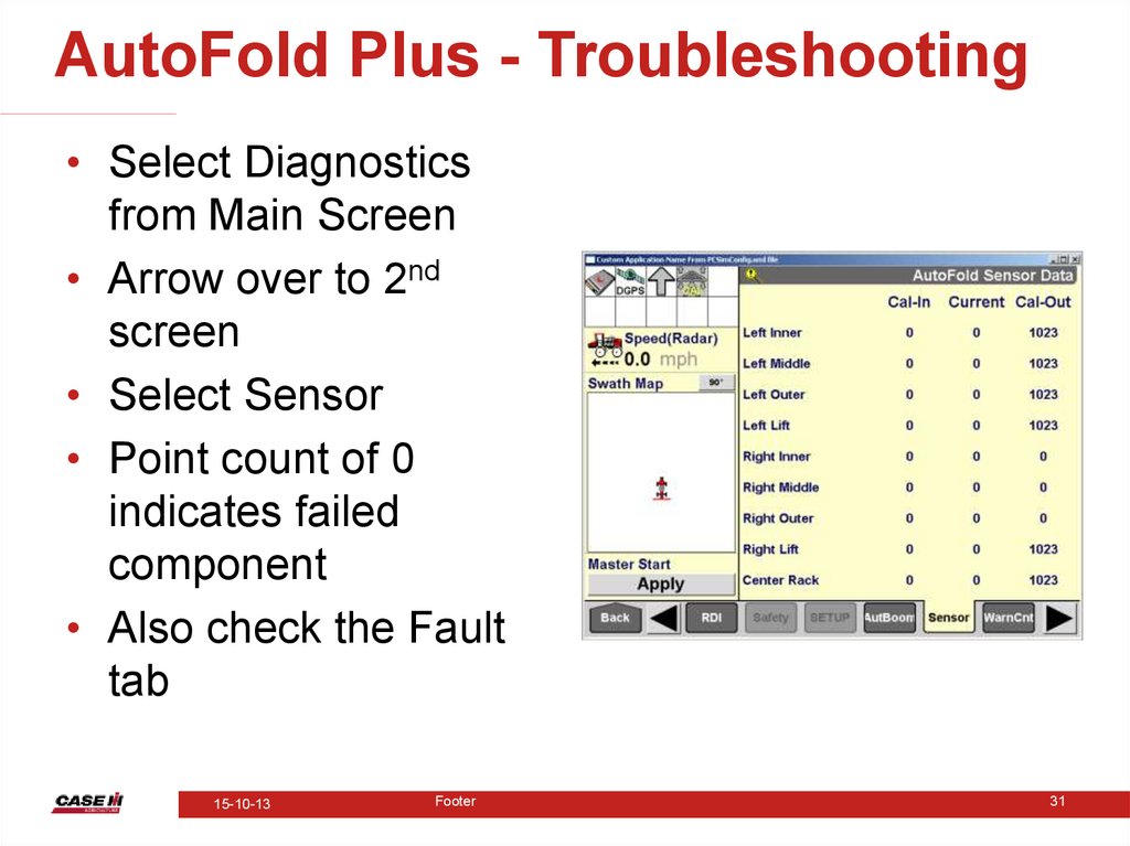
AutoFold Plus - Troubleshooting• Select Diagnostics
from Main Screen
• Arrow over to 2nd
screen
• Select Sensor
• Point count of 0
indicates failed
component
• Also check the Fault
tab
15-10-13
Footer
31
22.
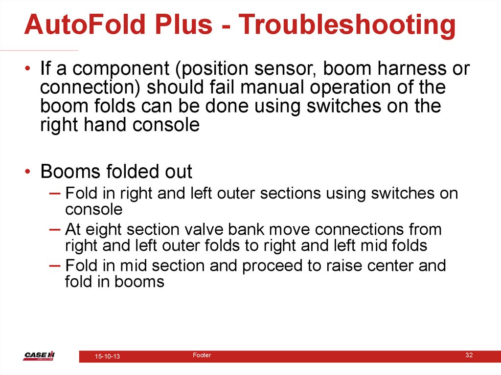
AutoFold Plus - Troubleshooting• If a component (position sensor, boom harness or
connection) should fail manual operation of the
boom folds can be done using switches on the
right hand console
• Booms folded out
– Fold in right and left outer sections using switches on
console
– At eight section valve bank move connections from
right and left outer folds to right and left mid folds
– Fold in mid section and proceed to raise center and
fold in booms
15-10-13
Footer
32
23.
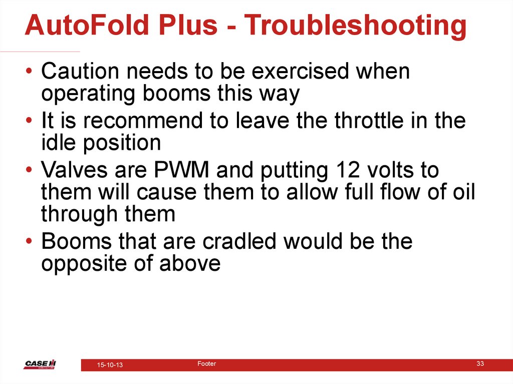
AutoFold Plus - Troubleshooting• Caution needs to be exercised when
operating booms this way
• It is recommend to leave the throttle in the
idle position
• Valves are PWM and putting 12 volts to
them will cause them to allow full flow of oil
through them
• Booms that are cradled would be the
opposite of above
15-10-13
Footer
33
24.
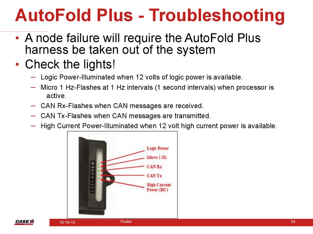
AutoFold Plus - Troubleshooting• A node failure will require the AutoFold Plus
harness be taken out of the system
• Check the lights!
– Logic Power-Illuminated when 12 volts of logic power is available.
– Micro 1 Hz-Flashes at 1 Hz intervals (1 second intervals) when processor is
–
–
–
active.
CAN Rx-Flashes when CAN messages are received.
CAN Tx-Flashes when CAN messages are transmitted.
High Current Power-Illuminated when 12 volt high current power is available.
15-10-13
Footer
34
25.
The End15-10-13
Footer
37