
 Промышленность
Похожие презентации:


Exhaust gas cleaning system
1.
EXHAUST GAS CLEANING SYSTEM( Operation Manual : MSC Hybrid with MGOH + BOTU M )
Park Myong GI
Enviro Team MEA
Wartsila
1
© Wärtsilä
I N TE R N A L
19.1.2025
[Presentation name / Author]
2.
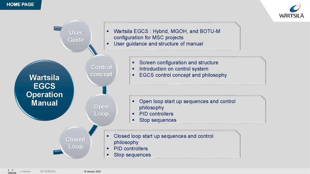
HOME PAGEWartsila EGCS : Hybrid, MGOH, and BOTU-M
configuration for MSC projects
User guidance and structure of manual
User
Guide
Control
concept
Wartsila
EGCS
Operation
Manual
Open
Loop
Closed
Loop
2 ©
Wärtsilä
© Wärtsilä
I N TE R N A L
19 January 2025
Screen configuration and structure
Introduction on control system
EGCS control concept and philosophy
Open loop start up sequences and control
philosophy
PID controllers
Stop sequences
Closed loop start up sequences and control
philosophy
PID controllers
Stop sequences
3.
RETURN TO OPELLOOP STARTING
USER GUIDE
PAGE
RETURN TO
CLOSED LOOP
STARTING PAGE
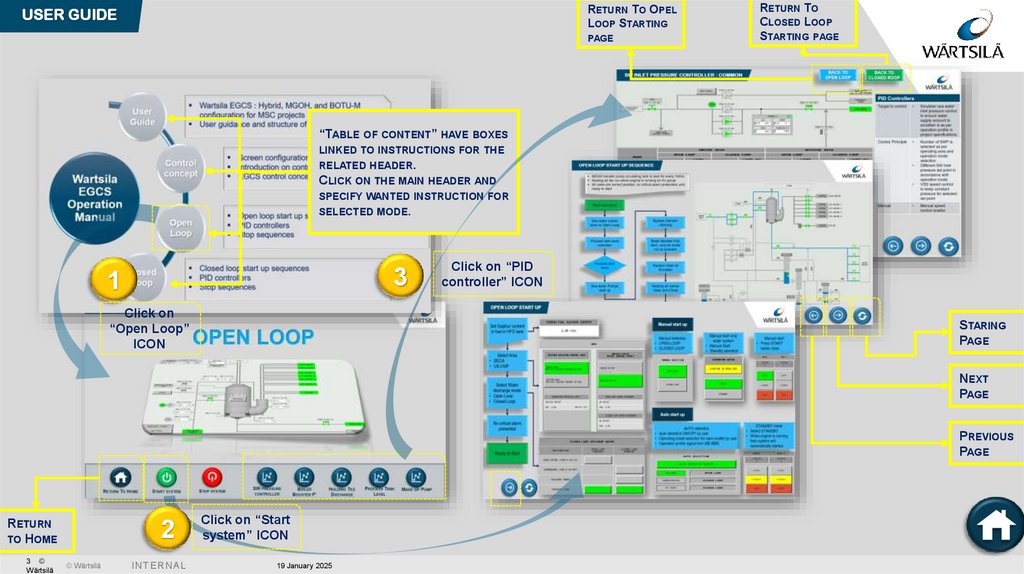
“TABLE OF CONTENT” HAVE BOXES
LINKED TO INSTRUCTIONS FOR THE
RELATED HEADER.
CLICK ON THE MAIN HEADER AND
SPECIFY WANTED INSTRUCTION FOR
SELECTED MODE.
3
1
Click on
“Open Loop”
ICON
Click on “PID
controller” ICON
STARING
PAGE
NEXT
PAGE
PREVIOUS
PAGE
RETURN
TO HOME
3 ©
Wärtsilä
2
© Wärtsilä
I N TE R N A L
Click on “Start
system” ICON
19 January 2025
4.
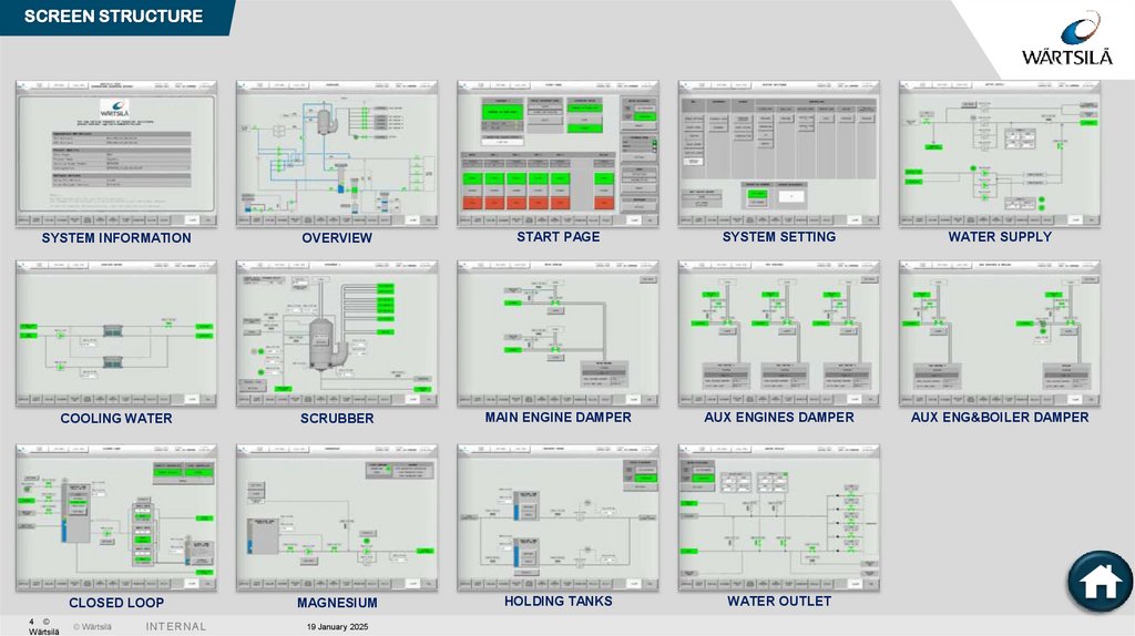
SCREEN STRUCTURESYSTEM INFORMATION
OVERVIEW
START PAGE
SYSTEM SETTING
WATER SUPPLY
COOLING WATER
SCRUBBER
MAIN ENGINE DAMPER
AUX ENGINES DAMPER
AUX ENG&BOILER DAMPER
CLOSED LOOP
MAGNESIUM
HOLDING TANKS
WATER OUTLET
4 ©
Wärtsilä
© Wärtsilä
I N TE R N A L
19 January 2025
5.
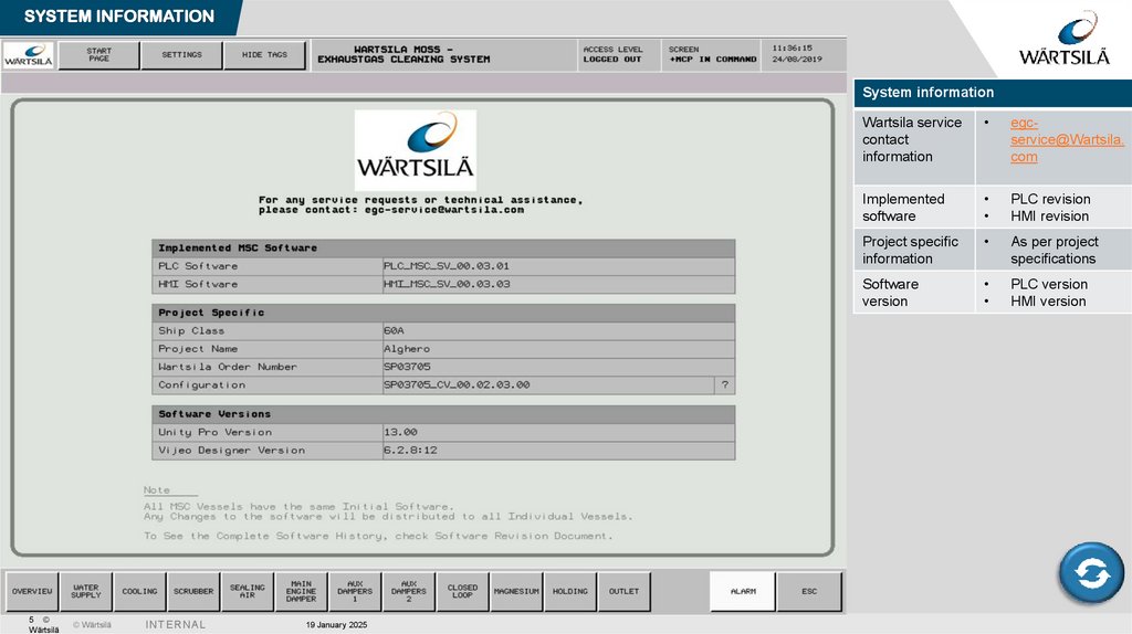
SYSTEM INFORMATIONSystem information
5 ©
Wärtsilä
© Wärtsilä
I N TE R N A L
19 January 2025
Wartsila service
contact
information
egcservice@Wartsila.
com
Implemented
software
PLC revision
HMI revision
Project specific
information
As per project
specifications
Software
version
PLC version
HMI version
6.
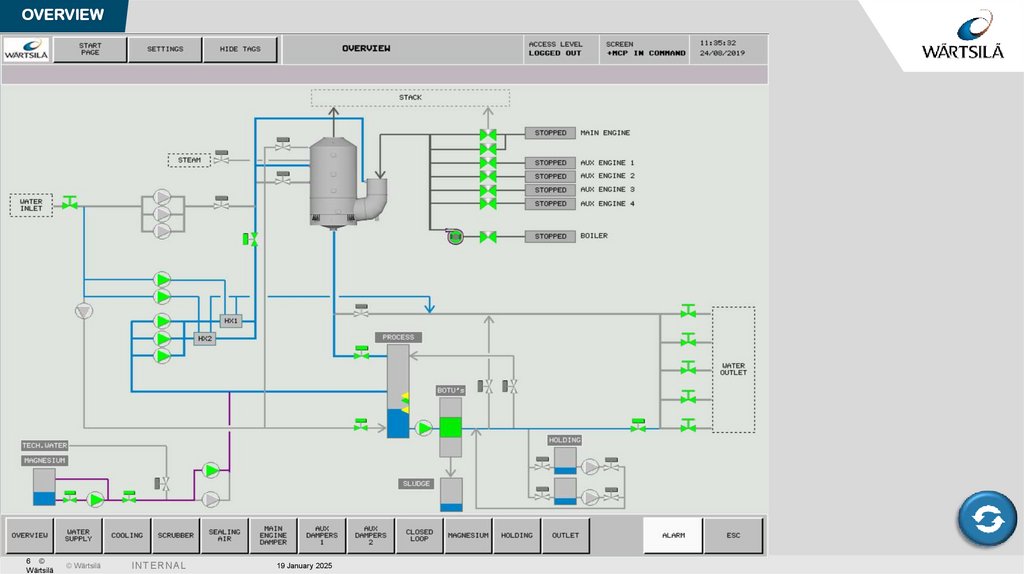
OVERVIEW6 ©
Wärtsilä
© Wärtsilä
I N TE R N A L
19 January 2025
7.
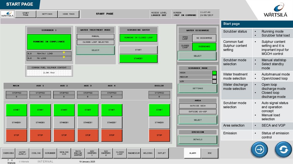
START PAGEStart page
Scrubber status
Running mode
Scrubber total load
Common fuel
Sulphur content
setting
Sulphur content
setting and it is
important input for
MGOH control
Scrubber mode
selection
Manual stat/stop
Select standby
mode
Water treatment
mode selection
Auto/manual mode
Open/closed loop
Water discharge
mode selection
Open loop
discharge mode
Closed loop
discharge mode
Scrubber mode
selection
7 ©
Wärtsilä
© Wärtsilä
I N TE R N A L
19 January 2025
Auto signal status
and operation
concept
Manual load
selection
Area selection
SECA and VGP
Emission
Status of emission
control
8.
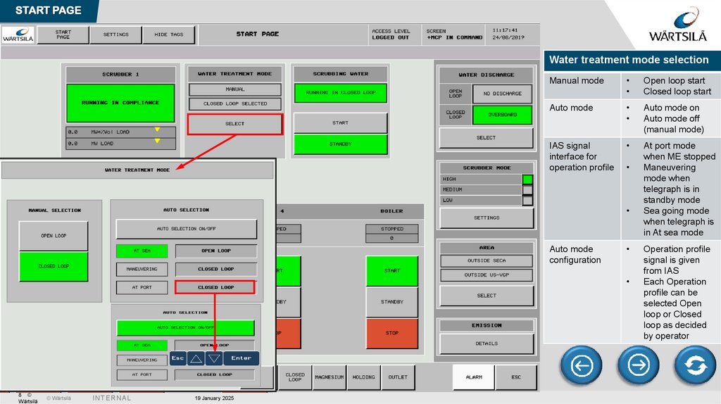
START PAGEWater treatment mode selection
Manual mode
Open loop start
Closed loop start
Auto mode
Auto mode on
Auto mode off
(manual mode)
IAS signal
interface for
operation profile
At port mode
when ME stopped
Maneuvering
mode when
telegraph is in
standby mode
Sea going mode
when telegraph is
in At sea mode
Auto mode
configuration
8 ©
Wärtsilä
© Wärtsilä
I N TE R N A L
19 January 2025
Operation profile
signal is given
from IAS
Each Operation
profile can be
selected Open
loop or Closed
loop as decided
by operator
9.
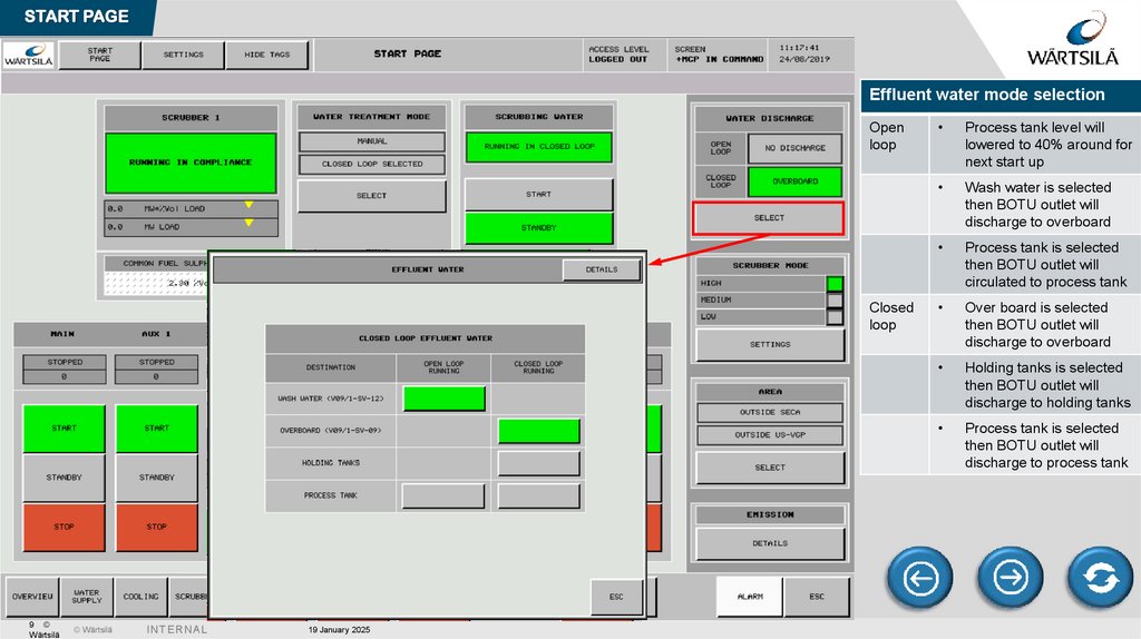
START PAGEEffluent water mode selection
Open
loop
Closed
loop
9 ©
Wärtsilä
© Wärtsilä
I N TE R N A L
19 January 2025
Process tank level will
lowered to 40% around for
next start up
Wash water is selected
then BOTU outlet will
discharge to overboard
Process tank is selected
then BOTU outlet will
circulated to process tank
Over board is selected
then BOTU outlet will
discharge to overboard
Holding tanks is selected
then BOTU outlet will
discharge to holding tanks
Process tank is selected
then BOTU outlet will
discharge to process tank
10.
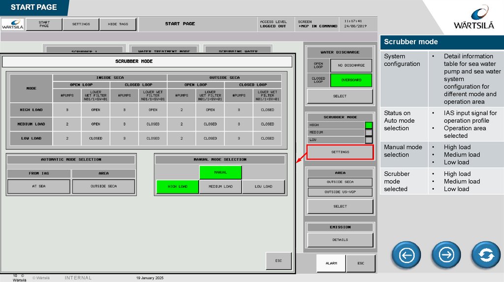
START PAGEScrubber mode
10 ©
Wärtsilä
© Wärtsilä
I N TE R N A L
19 January 2025
System
configuration
Detail information
table for sea water
pump and sea water
system
configuration for
different mode and
operation area
Status on
Auto mode
selection
IAS input signal for
operation profile
Operation area
selected
Manual mode
selection
High load
Medium load
Low load
Scrubber
mode
selected
High load
Medium load
Low load
11.
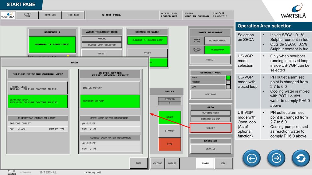
START PAGEOperation Area selection
Selection
on SECA
US-VGP
mode
selection
Only when scrubber
running in closed loop
inside US-VGP can be
selected
US-VGP
mode with
closed loop
PH outlet alarm set
point is changed from
2.7 to 6.0
Cooling water is mixed
with BOTH outlet
water to comply PH6.0
above
US-VGP
mode with
Open loop
(As of
optional
function)
11 ©
Wärtsilä
© Wärtsilä
I N TE R N A L
19 January 2025
Inside SECA : 0.1%
Sulphur content in fuel
Outside SECA : 0.5%
Sulphur content in fuel
PH outlet alarm set
point is changed from
2.7 to 6.0
Cooling pump is used
as reaction water to
comply PH6.0 above
12.
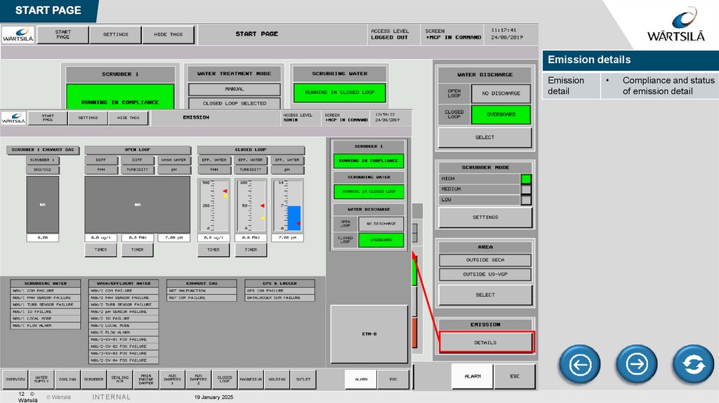
START PAGEEmission details
Emission
detail
12 ©
Wärtsilä
© Wärtsilä
I N TE R N A L
19 January 2025
Compliance and status
of emission detail
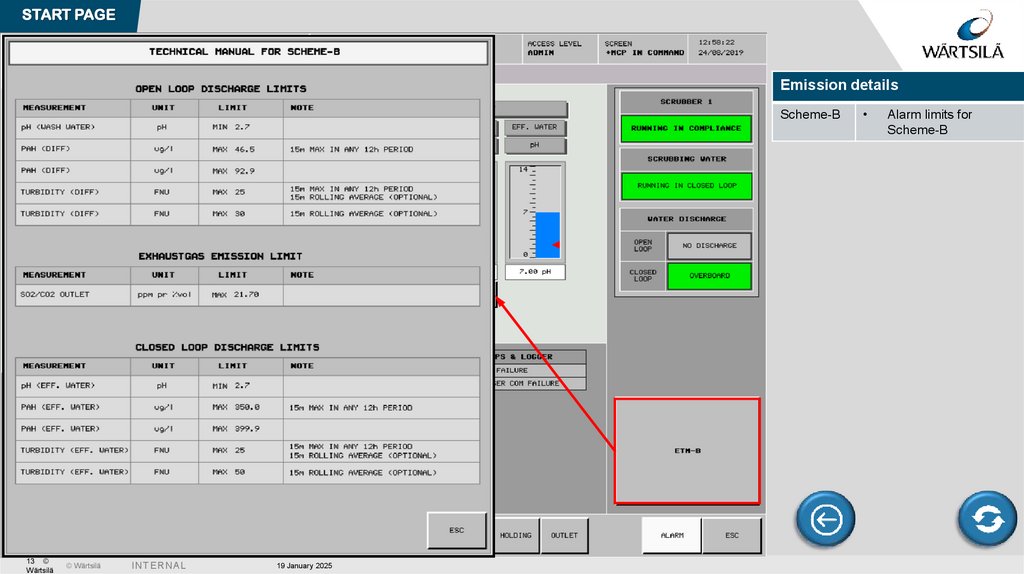
13.
START PAGEEmission details
Scheme-B
13 ©
Wärtsilä
© Wärtsilä
I N TE R N A L
19 January 2025
Alarm limits for
Scheme-B
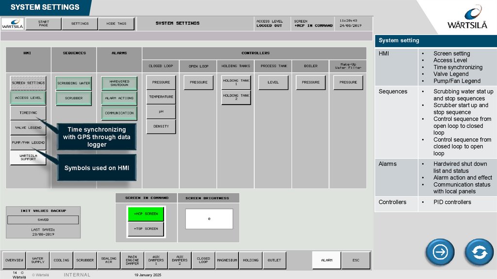
14.
SYSTEM SETTINGSSystem setting
HMI
Screen setting
Access Level
Time synchronizing
Valve Legend
Pump/Fan Legend
Sequences
Scrubbing water stat up
and stop sequences
Scrubber start up and
stop sequence
Control sequence from
open loop to closed
loop
Control sequence from
closed loop to open
loop
Time synchronizing
with GPS through data
logger
Alarms
Symbols used on HMI
Controllers
14 ©
Wärtsilä
© Wärtsilä
I N TE R N A L
19 January 2025
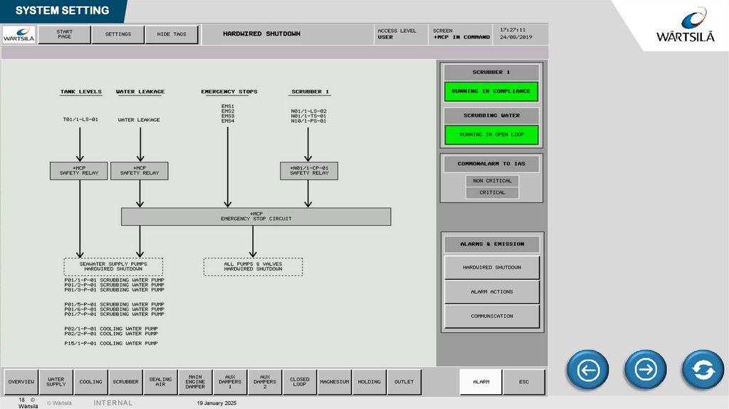
Hardwired shut down
list and status
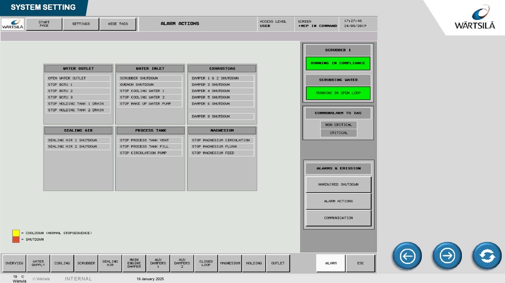
Alarm action and effect
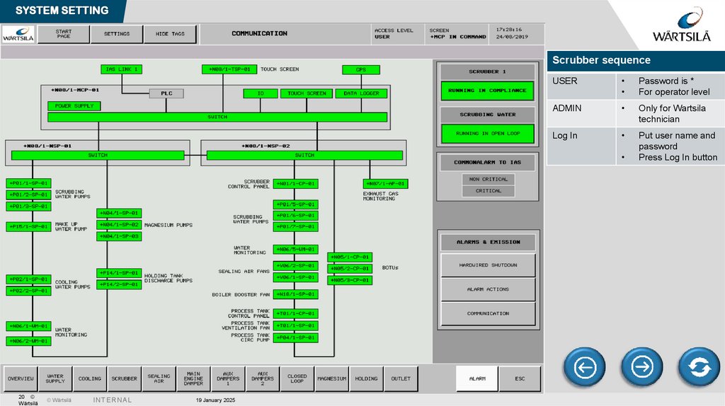
Communication status
with local panels
PID controllers
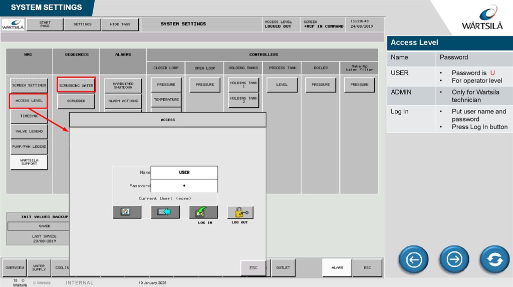
15.
SYSTEM SETTINGSAccess Level
Name
Password
USER
Password is U
For operator level
ADMIN
Only for Wartsila
technician
Log In
Put user name and
password
Press Log In button
15 ©
Wärtsilä
© Wärtsilä
I N TE R N A L
19 January 2025
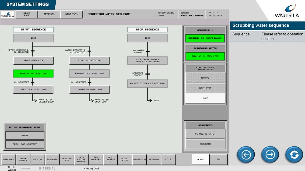
16.
SYSTEM SETTINGSScrubbing water sequence
Sequence
16 ©
Wärtsilä
© Wärtsilä
I N TE R N A L
19 January 2025
Please refer to operation
section
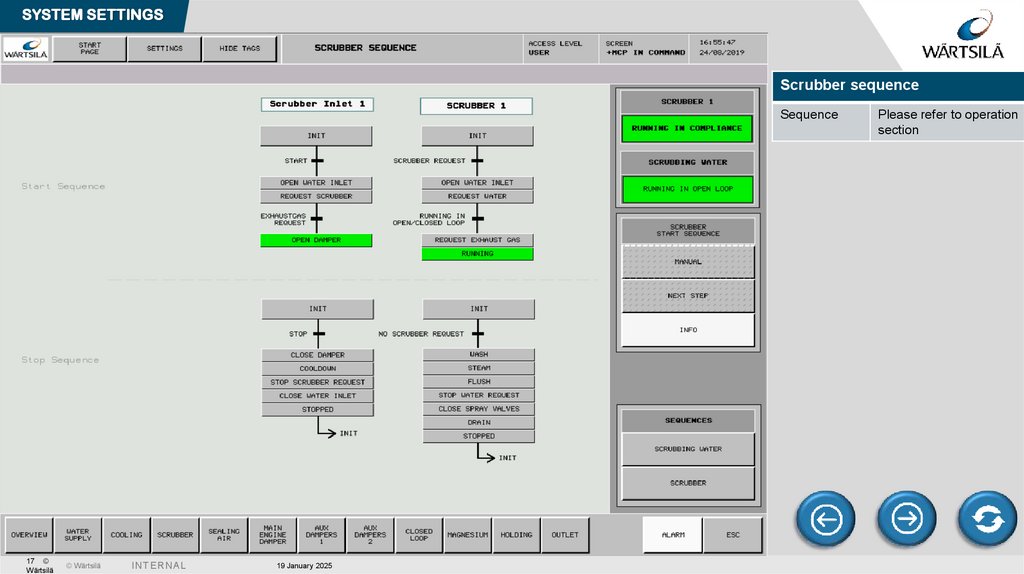
17.
SYSTEM SETTINGSScrubber sequence
Sequence
17 ©
Wärtsilä
© Wärtsilä
I N TE R N A L
19 January 2025
Please refer to operation
section
18.
SYSTEM SETTING18 ©
Wärtsilä
© Wärtsilä
I N TE R N A L
19 January 2025
19.
SYSTEM SETTING19 ©
Wärtsilä
© Wärtsilä
I N TE R N A L
19 January 2025
20.
SYSTEM SETTINGScrubber sequence
USER
Password is *
For operator level
ADMIN
Only for Wartsila
technician
Log In
Put user name and
password
Press Log In button
20 ©
Wärtsilä
© Wärtsilä
I N TE R N A L
19 January 2025
21.
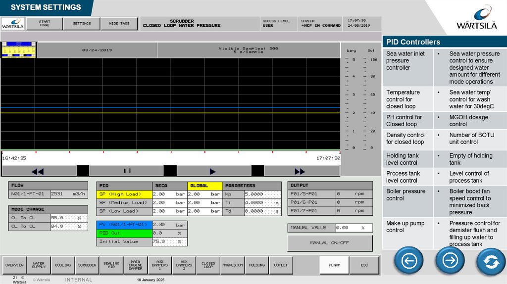
SYSTEM SETTINGSPID Controllers
21 ©
Wärtsilä
© Wärtsilä
I N TE R N A L
19 January 2025
Sea water inlet
pressure
controller
Sea water pressure
control to ensure
designed water
amount for different
mode operations
Temperature
control for
closed loop
Sea water temp’
control for wash
water for 30degC
PH control for
Closed loop
MGOH dosage
control
Density control
for closed loop
Number of BOTU
unit control
Holding tank
level control
Empty of holding
tank
Process tank
level control
Level control of
process tank
Boiler pressure
control
Boiler boost fan
speed control to
minimized back
pressure
Make up pump
control
Pressure control for
demister flush and
filling up water to
process tank
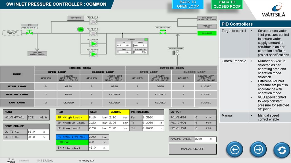
22.
SW INLET PRESSURE CONTROLLER : COMMONBACK TO
OPEN LOOP
BACK TO
CLOSED ROOP
PID Controllers
Target to control
Scrubber sea water
inlet pressure control
to ensure water
supply amount to
scrubber is as per
operation profile in
project specifications
Control Principle
Number of SWP is
selected as per
operating area and
operation mode
selection
Different SW inlet
pressure set point in
accordance with
operation mode
VSD speed control
to keep constant
pressure for selected
set point
Manual
22 ©
Wärtsilä
© Wärtsilä
I N TE R N A L
19 January 2025
Manual speed
control enable
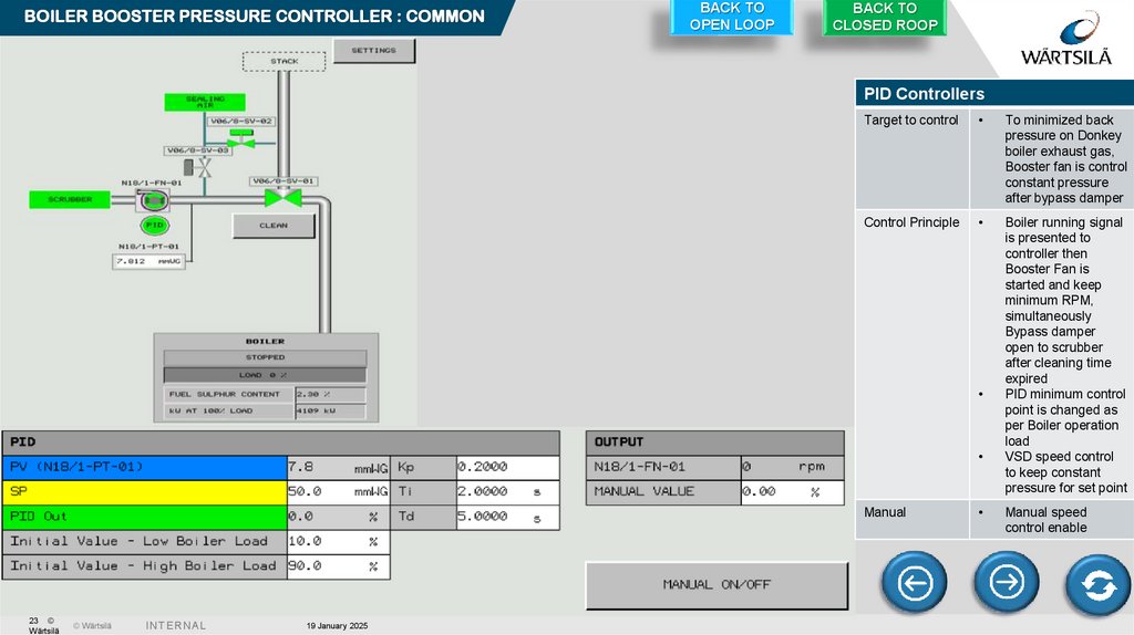
23.
BOILER BOOSTER PRESSURE CONTROLLER : COMMONBACK TO
OPEN LOOP
BACK TO
CLOSED ROOP
PID Controllers
Target to control
To minimized back
pressure on Donkey
boiler exhaust gas,
Booster fan is control
constant pressure
after bypass damper
Control Principle
Boiler running signal
is presented to
controller then
Booster Fan is
started and keep
minimum RPM,
simultaneously
Bypass damper
open to scrubber
after cleaning time
expired
PID minimum control
point is changed as
per Boiler operation
load
VSD speed control
to keep constant
pressure for set point
Manual
23 ©
Wärtsilä
© Wärtsilä
I N TE R N A L
19 January 2025
Manual speed
control enable
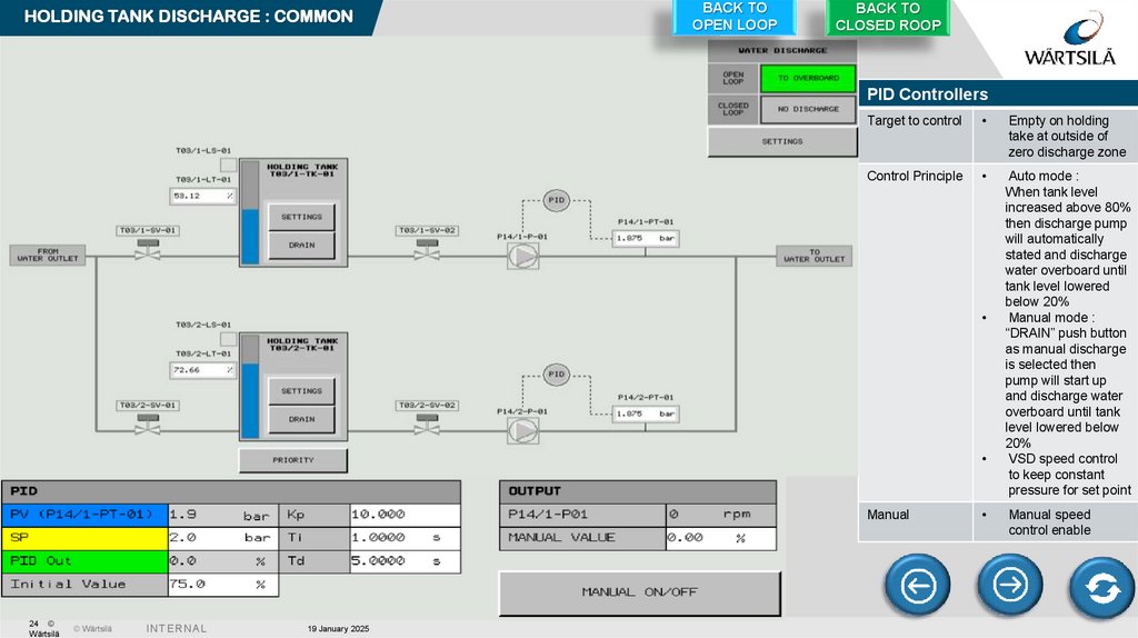
24.
HOLDING TANK DISCHARGE : COMMONBACK TO
OPEN LOOP
BACK TO
CLOSED ROOP
PID Controllers
Target to control
Empty on holding
take at outside of
zero discharge zone
Control Principle
Auto mode :
When tank level
increased above 80%
then discharge pump
will automatically
stated and discharge
water overboard until
tank level lowered
below 20%
Manual mode :
“DRAIN” push button
as manual discharge
is selected then
pump will start up
and discharge water
overboard until tank
level lowered below
20%
VSD speed control
to keep constant
pressure for set point
Manual
24 ©
Wärtsilä
© Wärtsilä
I N TE R N A L
19 January 2025
Manual speed
control enable
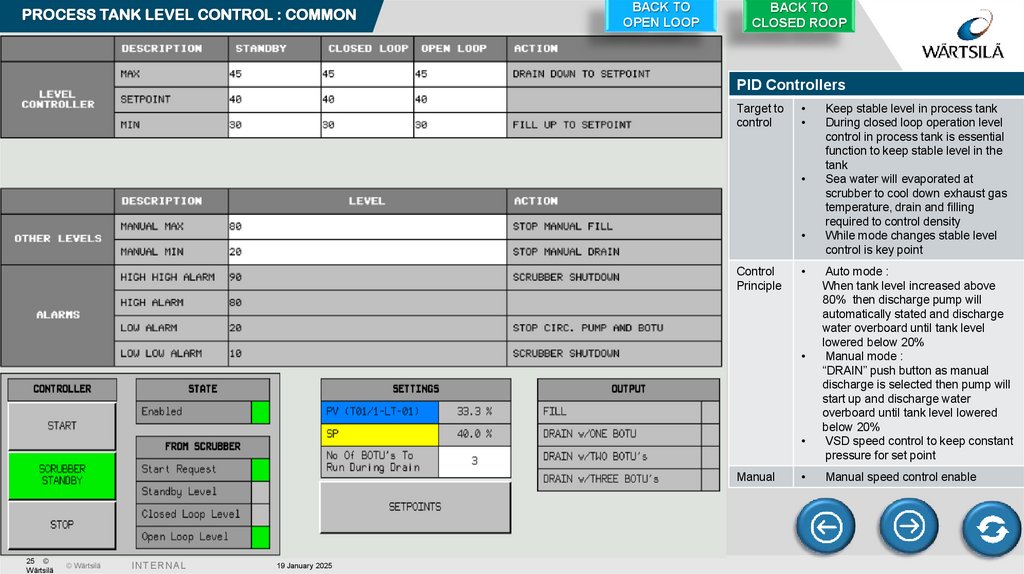
25.
PROCESS TANK LEVEL CONTROL : COMMONBACK TO
OPEN LOOP
BACK TO
CLOSED ROOP
PID Controllers
Target to
control
Control
Principle
Manual
25 ©
Wärtsilä
© Wärtsilä
I N TE R N A L
19 January 2025
Keep stable level in process tank
During closed loop operation level
control in process tank is essential
function to keep stable level in the
tank
Sea water will evaporated at
scrubber to cool down exhaust gas
temperature, drain and filling
required to control density
While mode changes stable level
control is key point
Auto mode :
When tank level increased above
80% then discharge pump will
automatically stated and discharge
water overboard until tank level
lowered below 20%
Manual mode :
“DRAIN” push button as manual
discharge is selected then pump will
start up and discharge water
overboard until tank level lowered
below 20%
VSD speed control to keep constant
pressure for set point
Manual speed control enable
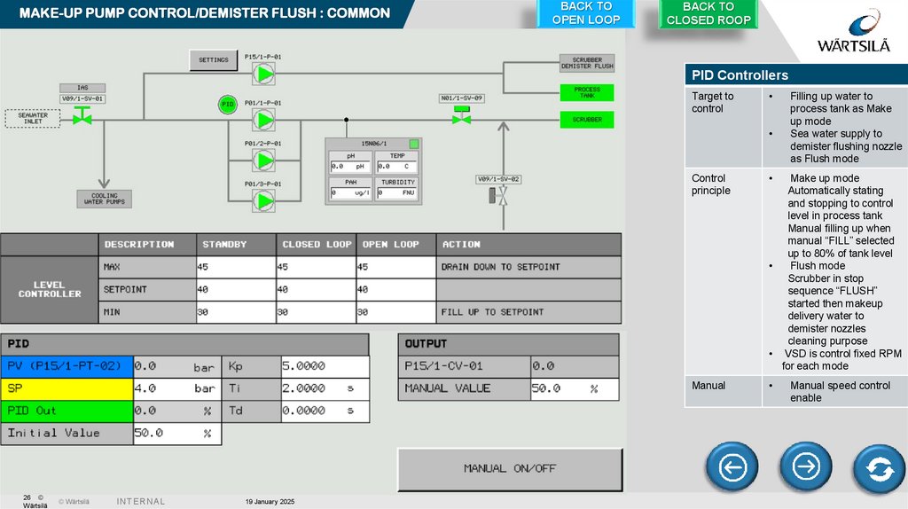
26.
MAKE-UP PUMP CONTROL/DEMISTER FLUSH : COMMONBACK TO
OPEN LOOP
BACK TO
CLOSED ROOP
PID Controllers
Target to
control
26 ©
Wärtsilä
© Wärtsilä
I N TE R N A L
19 January 2025
Control
principle
Manual
Filling up water to
process tank as Make
up mode
Sea water supply to
demister flushing nozzle
as Flush mode
Make up mode
Automatically stating
and stopping to control
level in process tank
Manual filling up when
manual “FILL” selected
up to 80% of tank level
Flush mode
Scrubber in stop
sequence “FLUSH”
started then makeup
delivery water to
demister nozzles
cleaning purpose
• VSD is control fixed RPM
for each mode
Manual speed control
enable
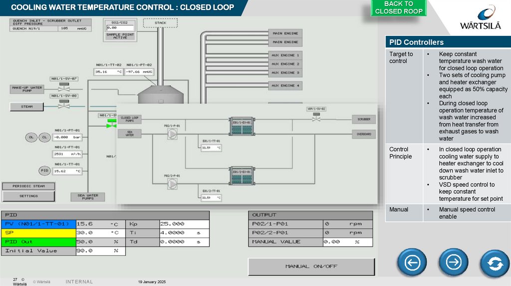
27.
COOLING WATER TEMPERATURE CONTROL : CLOSED LOOPBACK TO
CLOSED ROOP
PID Controllers
Target to
control
Control
Principle
Manual
27 ©
Wärtsilä
© Wärtsilä
I N TE R N A L
19 January 2025
Keep constant
temperature wash water
for closed loop operation
Two sets of cooling pump
and heater exchanger
equipped as 50% capacity
each
During closed loop
operation temperature of
wash water increased
from heat transfer from
exhaust gases to wash
water
In closed loop operation
cooling water supply to
heater exchanger to cool
down wash water inlet to
scrubber
VSD speed control to
keep constant
temperature for set point
Manual speed control
enable
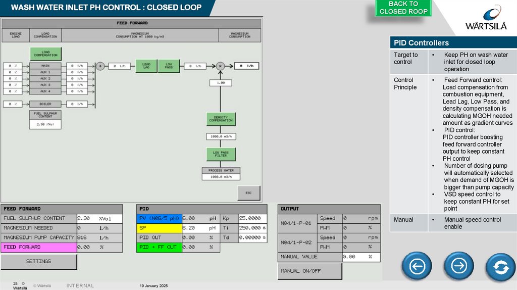
28.
WASH WATER INLET PH CONTROL : CLOSED LOOPBACK TO
CLOSED ROOP
PID Controllers
Target to
control
Keep PH on wash water
inlet for closed loop
operation
Control
Principle
Feed Forward control:
Load compensation from
combustion equipment,
Lead Lag, Low Pass, and
density compensation is
calculating MGOH needed
amount as gradient curves
PID control:
PID controller boosting
feed forward controller
output to keep constant
PH control
Number of dosing pump
will automatically selected
when demand of MGOH is
bigger than pump capacity
VSD speed control to
keep constant PH for set
point
Manual
28 ©
Wärtsilä
© Wärtsilä
I N TE R N A L
19 January 2025
Manual speed control
enable
29.
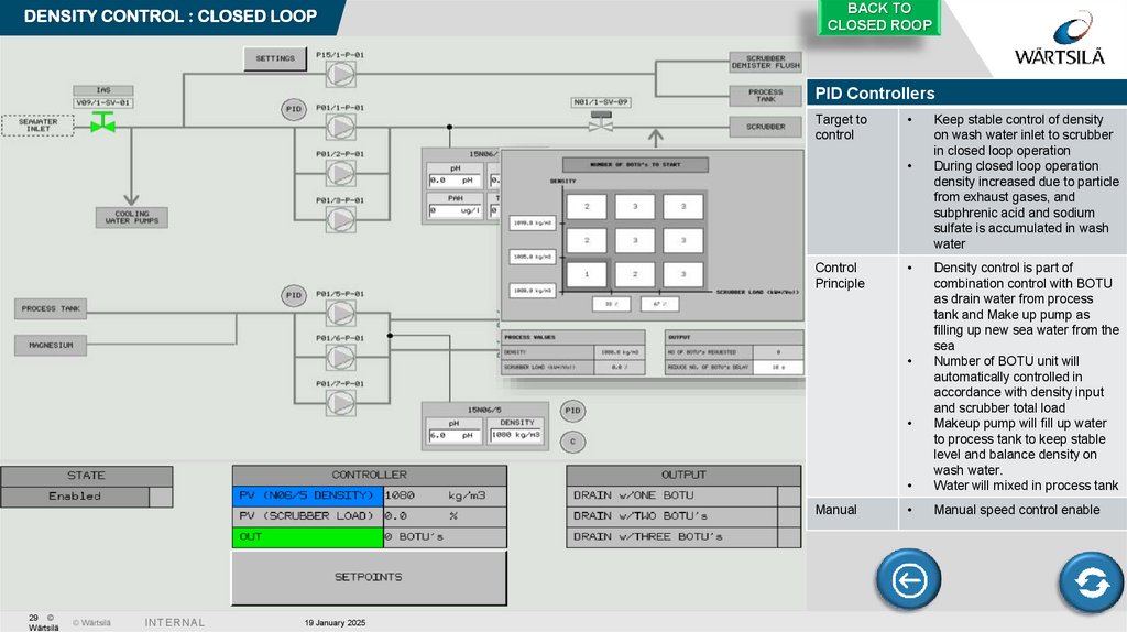
DENSITY CONTROL : CLOSED LOOPBACK TO
CLOSED ROOP
PID Controllers
Target to
control
Control
Principle
Density control is part of
combination control with BOTU
as drain water from process
tank and Make up pump as
filling up new sea water from the
sea
Number of BOTU unit will
automatically controlled in
accordance with density input
and scrubber total load
Makeup pump will fill up water
to process tank to keep stable
level and balance density on
wash water.
Water will mixed in process tank
Manual speed control enable
Manual
29 ©
Wärtsilä
© Wärtsilä
I N TE R N A L
19 January 2025
Keep stable control of density
on wash water inlet to scrubber
in closed loop operation
During closed loop operation
density increased due to particle
from exhaust gases, and
subphrenic acid and sodium
sulfate is accumulated in wash
water
30.
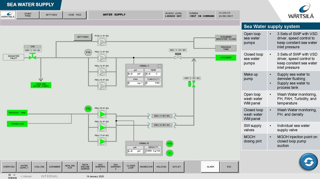
SEA WATER SUPPLYSea Water supply system
Open loop
sea water
pumps
3 Sets of SWP with VSD
driver, speed control to
keep constant sea water
inlet pressure
Closed loop
sea water
pumps
3 Sets of SWP with VSD
driver, speed control to
keep constant sea water
inlet pressure
Make up
pump
Supply sea water to
demister flushing
Supply sea water to
process tank
30 ©
Wärtsilä
© Wärtsilä
I N TE R N A L
19 January 2025
Open loop
wash water
WM panel
Wash Water monitoring,
PH, PAH, Turbidity, and
temperature
Closed loop
wash water
WM panel
Wash Water monitoring,
PH, and density
SW supply
valves
Individual sea water
supply valve
MGOH
dosing pint
MGOH injection point on
closed loop pump
suction
31.
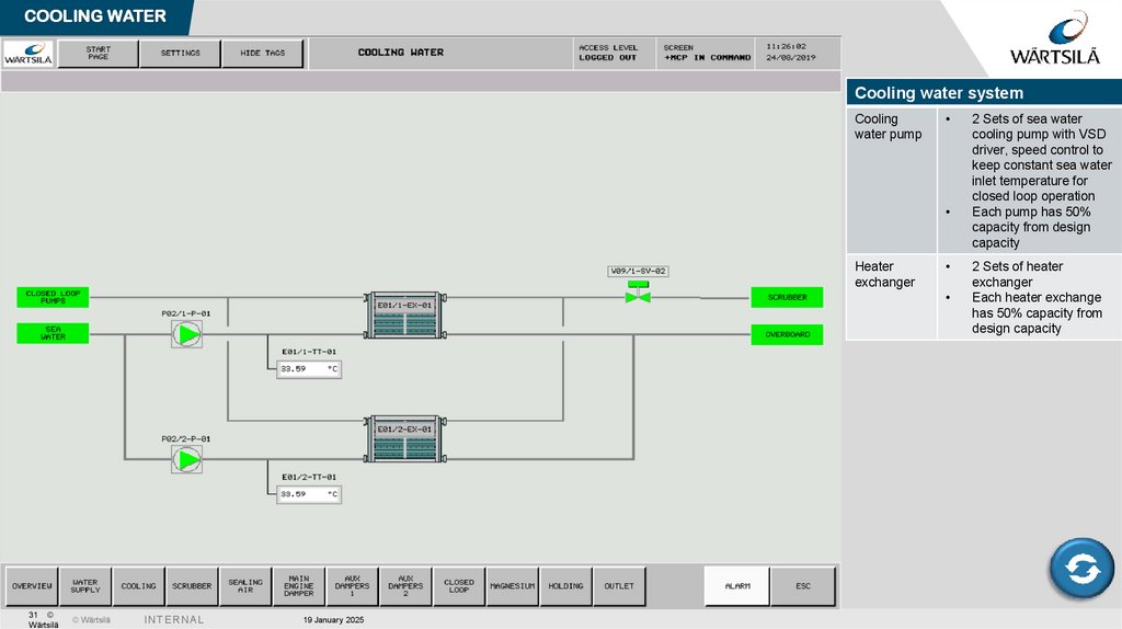
COOLING WATERCooling water system
Cooling
water pump
Heater
exchanger
31 ©
Wärtsilä
© Wärtsilä
I N TE R N A L
19 January 2025
2 Sets of sea water
cooling pump with VSD
driver, speed control to
keep constant sea water
inlet temperature for
closed loop operation
Each pump has 50%
capacity from design
capacity
2 Sets of heater
exchanger
Each heater exchange
has 50% capacity from
design capacity
32.
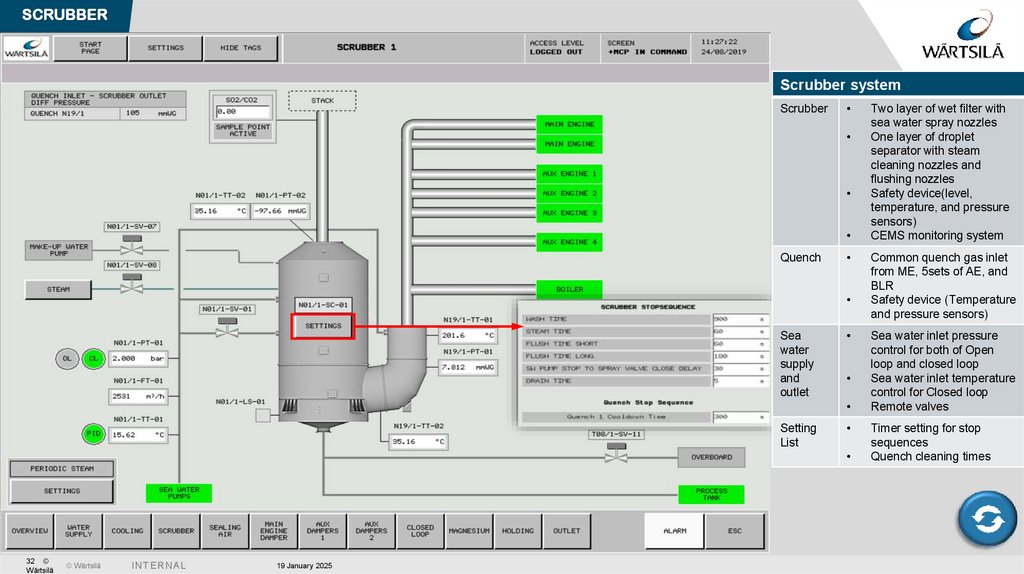
SCRUBBERScrubber system
Scrubber
Quench
Sea
water
supply
and
outlet
Setting
List
32 ©
Wärtsilä
© Wärtsilä
I N TE R N A L
19 January 2025
Two layer of wet filter with
sea water spray nozzles
One layer of droplet
separator with steam
cleaning nozzles and
flushing nozzles
Safety device(level,
temperature, and pressure
sensors)
CEMS monitoring system
Common quench gas inlet
from ME, 5sets of AE, and
BLR
Safety device (Temperature
and pressure sensors)
Sea water inlet pressure
control for both of Open
loop and closed loop
Sea water inlet temperature
control for Closed loop
Remote valves
Timer setting for stop
sequences
Quench cleaning times
33.
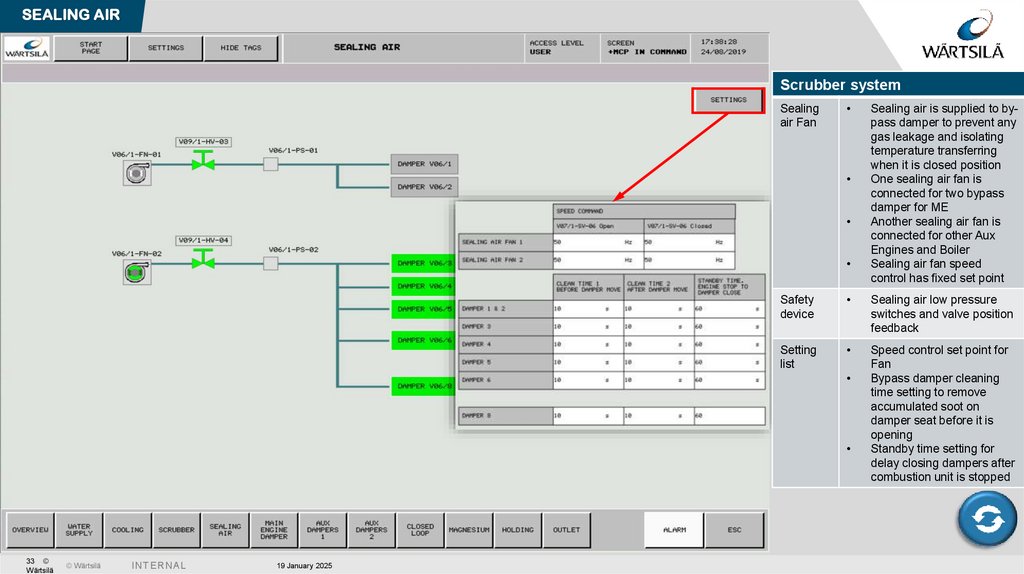
SEALING AIRScrubber system
Sealing
air Fan
Safety
device
Sealing air low pressure
switches and valve position
feedback
Setting
list
Speed control set point for
Fan
Bypass damper cleaning
time setting to remove
accumulated soot on
damper seat before it is
opening
Standby time setting for
delay closing dampers after
combustion unit is stopped
33 ©
Wärtsilä
© Wärtsilä
I N TE R N A L
19 January 2025
Sealing air is supplied to bypass damper to prevent any
gas leakage and isolating
temperature transferring
when it is closed position
One sealing air fan is
connected for two bypass
damper for ME
Another sealing air fan is
connected for other Aux
Engines and Boiler
Sealing air fan speed
control has fixed set point
34.
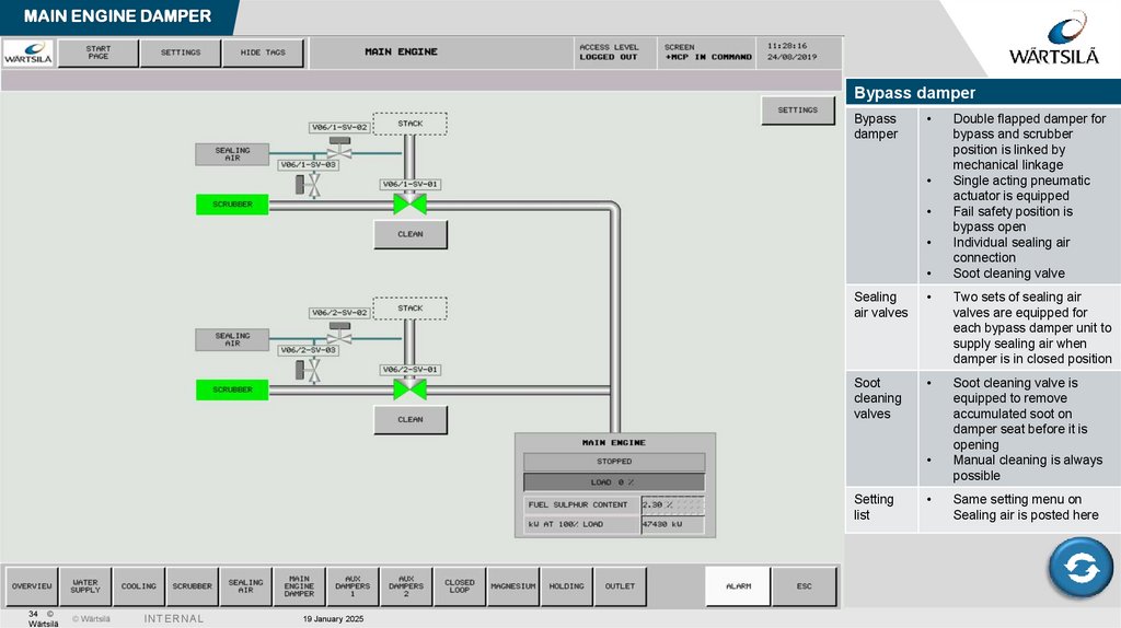
MAIN ENGINE DAMPERBypass damper
Bypass
damper
Sealing
air valves
Two sets of sealing air
valves are equipped for
each bypass damper unit to
supply sealing air when
damper is in closed position
Soot
cleaning
valves
Soot cleaning valve is
equipped to remove
accumulated soot on
damper seat before it is
opening
Manual cleaning is always
possible
Setting
list
34 ©
Wärtsilä
© Wärtsilä
I N TE R N A L
19 January 2025
Double flapped damper for
bypass and scrubber
position is linked by
mechanical linkage
Single acting pneumatic
actuator is equipped
Fail safety position is
bypass open
Individual sealing air
connection
Soot cleaning valve
Same setting menu on
Sealing air is posted here
35.
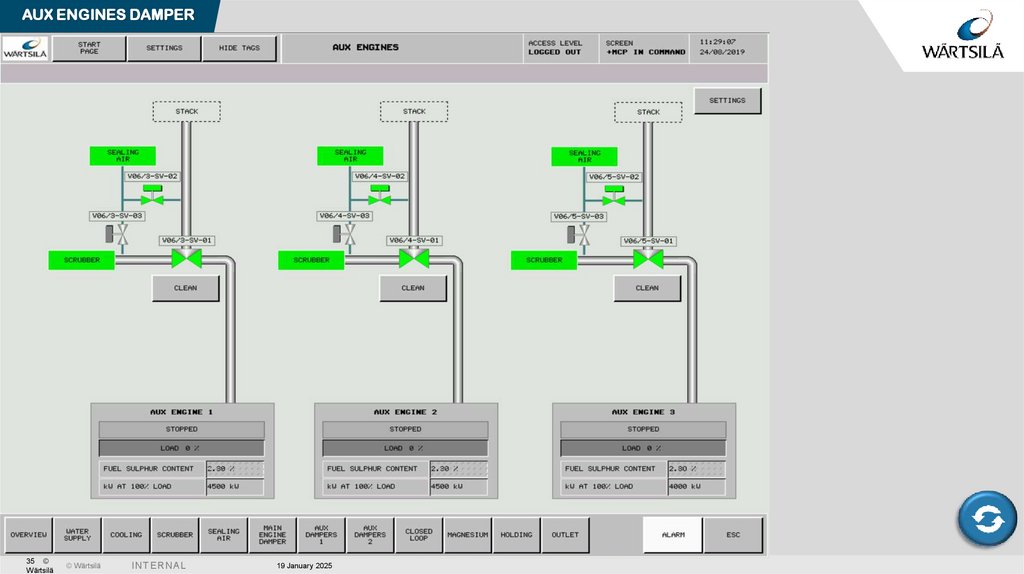
AUX ENGINES DAMPER35 ©
Wärtsilä
© Wärtsilä
I N TE R N A L
19 January 2025
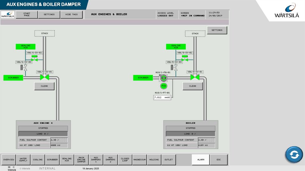
36.
AUX ENGINES & BOILER DAMPER36 ©
Wärtsilä
© Wärtsilä
I N TE R N A L
19 January 2025
37.
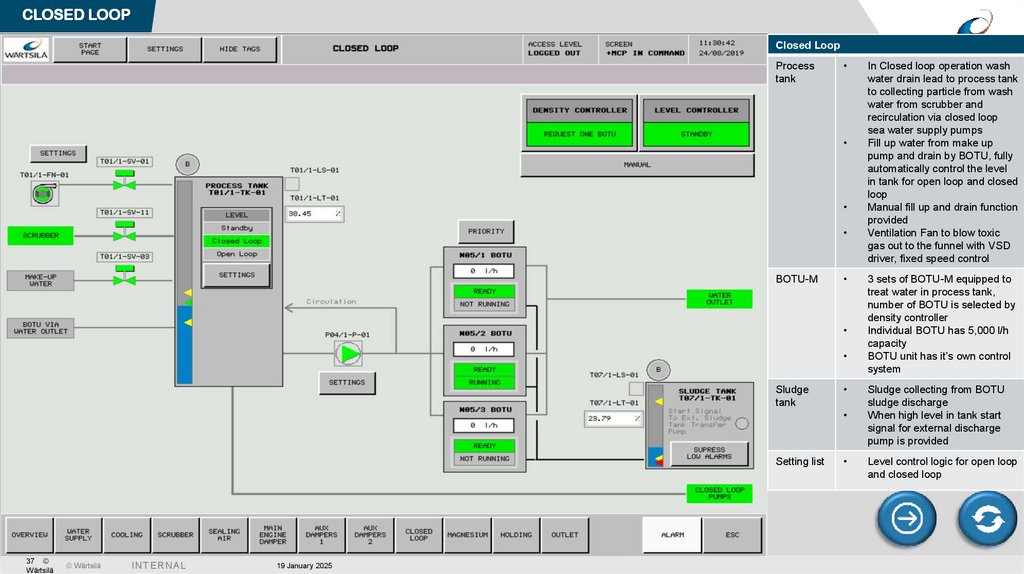
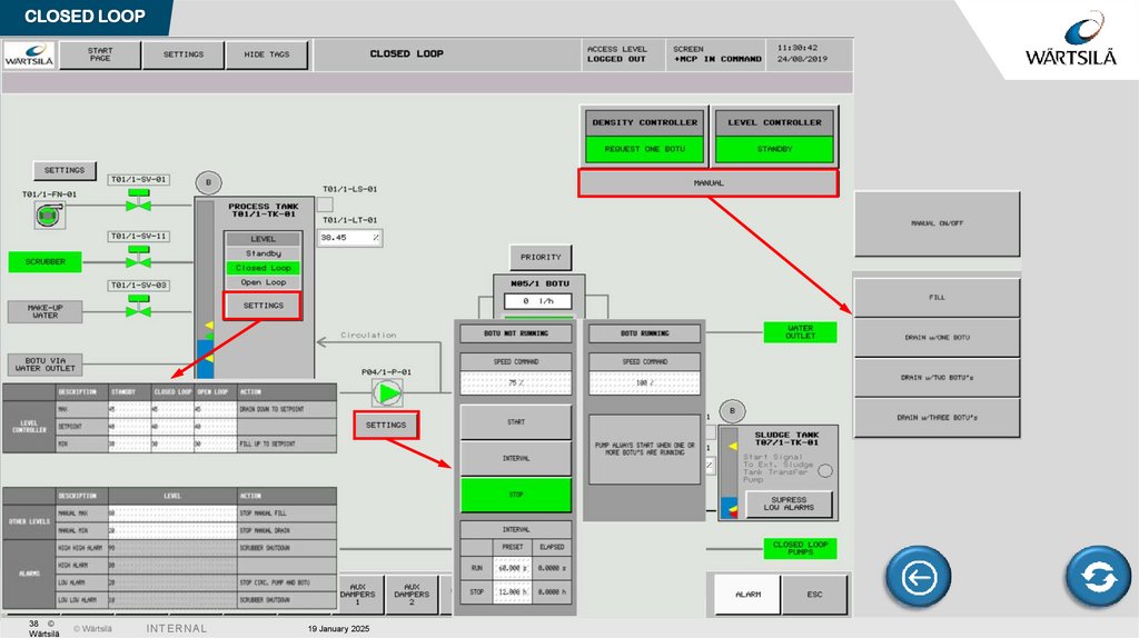
CLOSED LOOPClosed Loop
Process
tank
BOTU-M
Sludge
tank
Setting list
37 ©
Wärtsilä
© Wärtsilä
I N TE R N A L
19 January 2025
In Closed loop operation wash
water drain lead to process tank
to collecting particle from wash
water from scrubber and
recirculation via closed loop
sea water supply pumps
Fill up water from make up
pump and drain by BOTU, fully
automatically control the level
in tank for open loop and closed
loop
Manual fill up and drain function
provided
Ventilation Fan to blow toxic
gas out to the funnel with VSD
driver, fixed speed control
3 sets of BOTU-M equipped to
treat water in process tank,
number of BOTU is selected by
density controller
Individual BOTU has 5,000 l/h
capacity
BOTU unit has it’s own control
system
Sludge collecting from BOTU
sludge discharge
When high level in tank start
signal for external discharge
pump is provided
Level control logic for open loop
and closed loop
38.
CLOSED LOOP38 ©
Wärtsilä
© Wärtsilä
I N TE R N A L
19 January 2025
39.
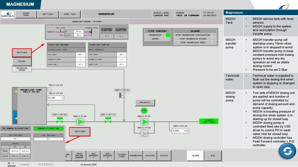
MAGNESIUMMagnesium
MGOH
Tank
MGOH
transfer
pump
Technical water is supplied to
flush out the dosing line when
system is stopping or changed
to open loop
MGOH
dosing
pump
Two sets of MGOH dosing unit
are applied and number of
pump will be controlled by
demand of dosing amount and
pump capacity
MGOH is boosting pressure of
dosing line when system is in
starting up for closed loop
MGOH dosing pump is
controlled feed rate by VSD
driver to control PH in wash
water inlet for closed loop
MGOH dosing controller has
Feed Forward controller + PID
controller
© Wärtsilä
I N TE R N A L
19 January 2025
MGOH transfer pump will
start/stop every 10min when
system is in stopped to avoid
MGOH transfer pump to keep
constant pressure inlet dosing
pumps to avoid any dry
operation as well as stable
dosing control
Pressure to be set 2.0bar
Technical
water
39 ©
Wärtsilä
MGOH service tank with level
sensors
MGOH supply to the system
and recirculation through
transfer pump
40.
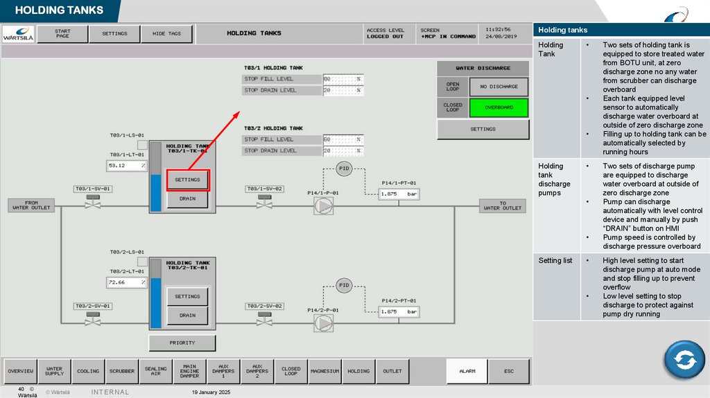
HOLDING TANKSHolding tanks
Holding
Tank
Holding
tank
discharge
pumps
Setting list
40 ©
Wärtsilä
© Wärtsilä
I N TE R N A L
19 January 2025
Two sets of holding tank is
equipped to store treated water
from BOTU unit, at zero
discharge zone no any water
from scrubber can discharge
overboard
Each tank equipped level
sensor to automatically
discharge water overboard at
outside of zero discharge zone
Filling up to holding tank can be
automatically selected by
running hours
Two sets of discharge pump
are equipped to discharge
water overboard at outside of
zero discharge zone
Pump can discharge
automatically with level control
device and manually by push
“DRAIN” button on HMI
Pump speed is controlled by
discharge pressure overboard
High level setting to start
discharge pump at auto mode
and stop filling up to prevent
overflow
Low level setting to stop
discharge to protect against
pump dry running
41.
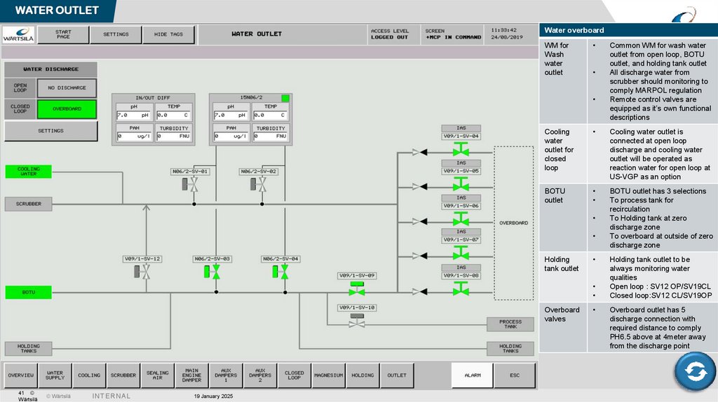
WATER OUTLETWater overboard
WM for
Wash
water
outlet
Cooling
water
outlet for
closed
loop
Cooling water outlet is
connected at open loop
discharge and cooling water
outlet will be operated as
reaction water for open loop at
US-VGP as an option
BOTU
outlet
BOTU outlet has 3 selections
To process tank for
recirculation
To Holding tank at zero
discharge zone
To overboard at outside of zero
discharge zone
Holding
tank outlet
Overboard
valves
41 ©
Wärtsilä
© Wärtsilä
I N TE R N A L
19 January 2025
Common WM for wash water
outlet from open loop, BOTU
outlet, and holding tank outlet
All discharge water from
scrubber should monitoring to
comply MARPOL regulation
Remote control valves are
equipped as it’s own functional
descriptions
Holding tank outlet to be
always monitoring water
qualities
Open loop : SV12 OP/SV19CL
Closed loop:SV12 CL/SV19OP
Overboard outlet has 5
discharge connection with
required distance to comply
PH6.5 above at 4meter away
from the discharge point
42.
OPEN LOOP START UPOPEN LOOP
RETURN TO HOME
42 ©
Wärtsilä
© Wärtsilä
I N TE R N A L
START SYSTEM
STOP SYSTEM
19 January 2025
SW PRESSURE
BOILER
CONTROLLER
BOOSTER P’
HOLDING TKS
DISCHARGE
PROCESS TANK
LEVEL
MAKE UP PUMP
43.
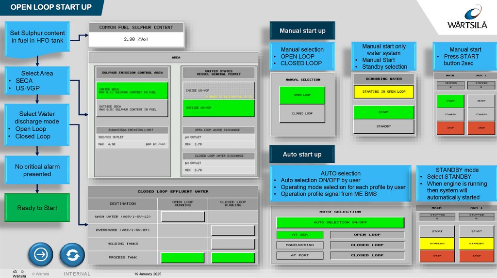
OPEN LOOP START UPManual start up
Set Sulphur content
in fuel in HFO tank
Manual selection
• OPEN LOOP
• CLOSED LOOP
Manual start only
water system
• Manual Start
• Standby selection
Manual start
• Press START
button 2sec
Select Area
• SECA
• US-VGP
Select Water
discharge mode
• Open Loop
• Closed Loop
Auto start up
No critical alarm
presented
AUTO selection
• Auto selection ON/OFF by user
• Operating mode selection for each profile by user
• Operation profile signal from ME BMS
Ready to Start
43 ©
Wärtsilä
© Wärtsilä
I N TE R N A L
19 January 2025
STANDBY mode
• Select STANDBY
• When engine is running
then system will
automatically started
44.
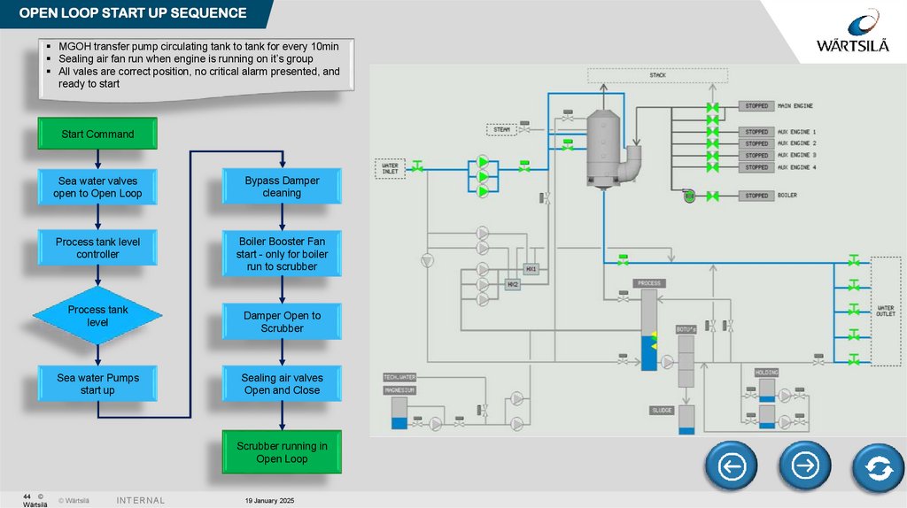
OPEN LOOP START UP SEQUENCEMGOH transfer pump circulating tank to tank for every 10min
Sealing air fan run when engine is running on it’s group
All vales are correct position, no critical alarm presented, and
ready to start
Start Command
Sea water valves
open to Open Loop
Bypass Damper
cleaning
Process tank level
controller
Boiler Booster Fan
start - only for boiler
run to scrubber
Process tank
level
Sea water Pumps
start up
Damper Open to
Scrubber
Sealing air valves
Open and Close
Scrubber running in
Open Loop
44 ©
Wärtsilä
© Wärtsilä
I N TE R N A L
19 January 2025
45.
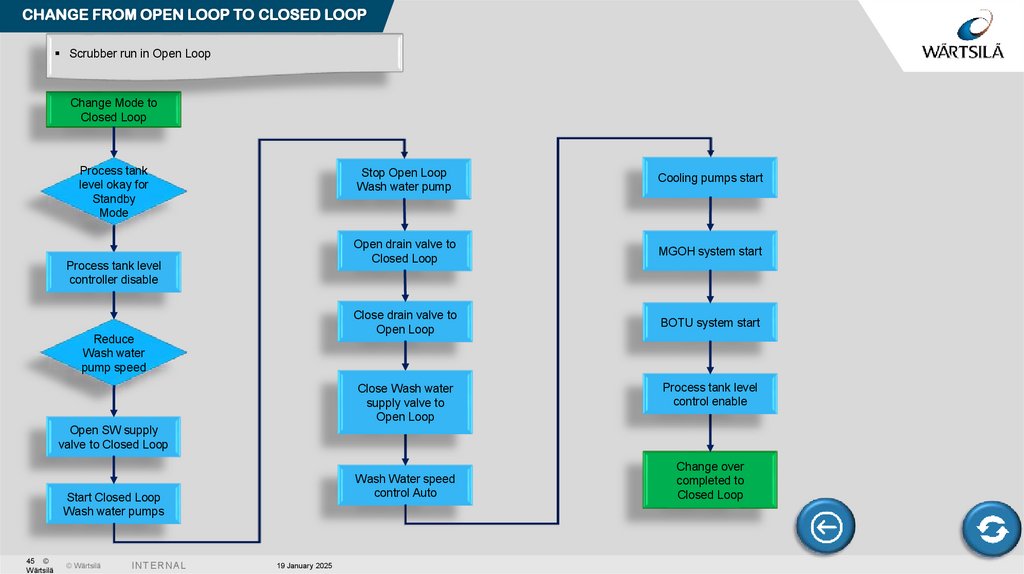
CHANGE FROM OPEN LOOP TO CLOSED LOOPScrubber run in Open Loop
Change Mode to
Closed Loop
Process tank
level okay for
Standby
Mode
Process tank level
controller disable
Reduce
Wash water
pump speed
Stop Open Loop
Wash water pump
Cooling pumps start
Open drain valve to
Closed Loop
MGOH system start
Close drain valve to
Open Loop
BOTU system start
Close Wash water
supply valve to
Open Loop
Process tank level
control enable
Open SW supply
valve to Closed Loop
Wash Water speed
control Auto
Start Closed Loop
Wash water pumps
45 ©
Wärtsilä
© Wärtsilä
I N TE R N A L
19 January 2025
Change over
completed to
Closed Loop
46.
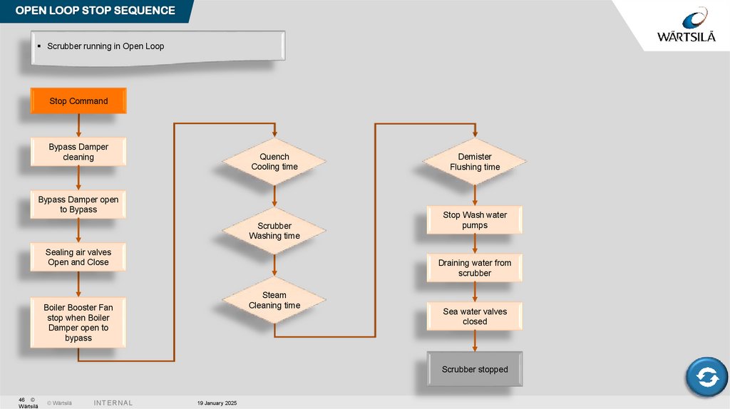
OPEN LOOP STOP SEQUENCEScrubber running in Open Loop
Stop Command
Bypass Damper
cleaning
Quench
Cooling time
Bypass Damper open
to Bypass
Scrubber
Washing time
Sealing air valves
Open and Close
Demister
Flushing time
Stop Wash water
pumps
Draining water from
scrubber
Steam
Cleaning time
Boiler Booster Fan
stop when Boiler
Damper open to
bypass
Sea water valves
closed
Scrubber stopped
46 ©
Wärtsilä
© Wärtsilä
I N TE R N A L
19 January 2025
47.
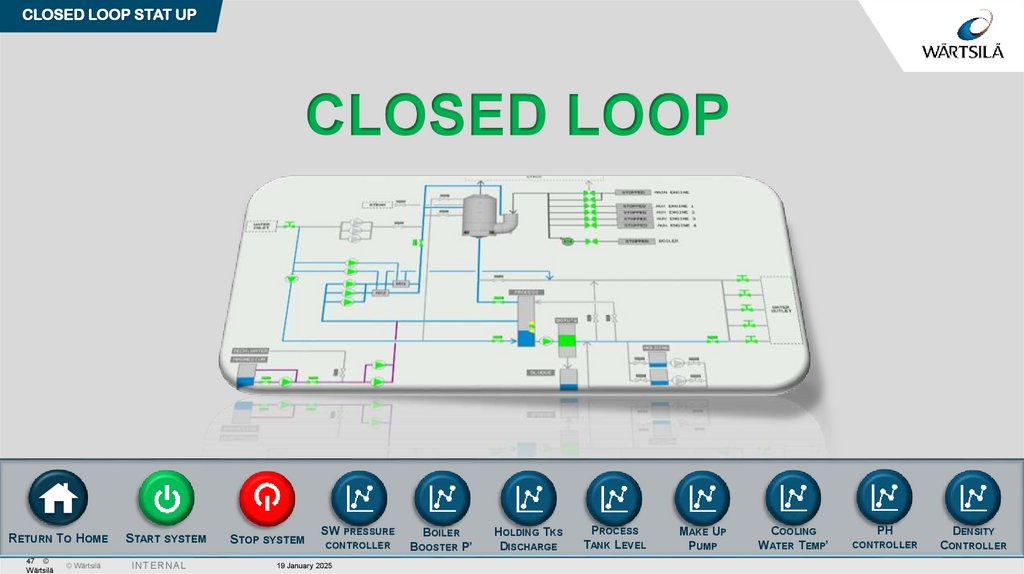
CLOSED LOOP STAT UPCLOSED LOOP
RETURN TO HOME
47 ©
Wärtsilä
© Wärtsilä
START SYSTEM
I N TE R N A L
STOP SYSTEM
SW PRESSURE
BOILER
CONTROLLER
BOOSTER P’
19 January 2025
HOLDING TKS
DISCHARGE
PROCESS
TANK LEVEL
MAKE UP
PUMP
COOLING
WATER TEMP’
PH
CONTROLLER
DENSITY
CONTROLLER
48.
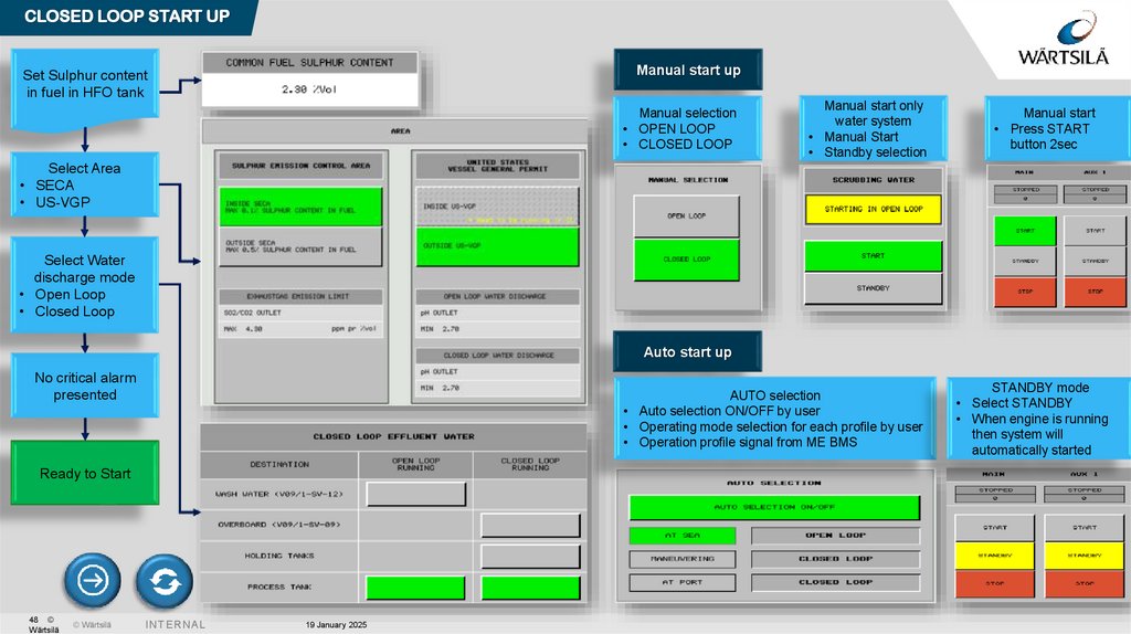
CLOSED LOOP START UPManual start up
Set Sulphur content
in fuel in HFO tank
Manual selection
• OPEN LOOP
• CLOSED LOOP
Manual start only
water system
• Manual Start
• Standby selection
Manual start
• Press START
button 2sec
Select Area
• SECA
• US-VGP
Select Water
discharge mode
• Open Loop
• Closed Loop
Auto start up
No critical alarm
presented
AUTO selection
• Auto selection ON/OFF by user
• Operating mode selection for each profile by user
• Operation profile signal from ME BMS
Ready to Start
48 ©
Wärtsilä
© Wärtsilä
I N TE R N A L
19 January 2025
STANDBY mode
• Select STANDBY
• When engine is running
then system will
automatically started
49.
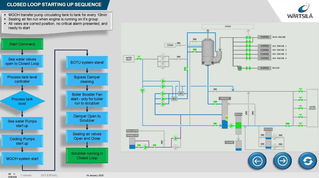
CLOSED LOOP STARTING UP SEQUENCEMGOH transfer pump circulating tank to tank for every 10min
Sealing air fan run when engine is running on it’s group
All vales are correct position, no critical alarm presented, and
ready to start
Start Command
Sea water valves
open to Closed Loop
BOTU system staret
Process tank level
controller
Bypass Damper
cleaning
Process tank
level
Boiler Booster Fan
start - only for boiler
run to scrubber
Damper Open to
Scrubber
Sea water Pumps
start up
Sealing air valves
Open and Close
Cooling Pumps
start up
Scrubber running in
Closed Loop
MGOH system start
49 ©
Wärtsilä
© Wärtsilä
I N TE R N A L
19 January 2025
50.
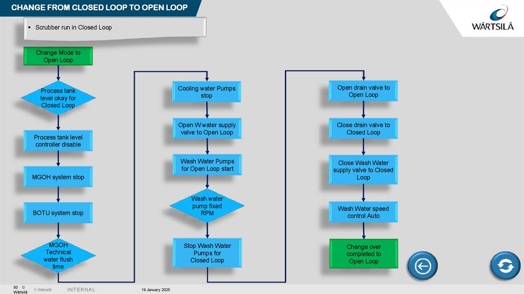
CHANGE FROM CLOSED LOOP TO OPEN LOOPScrubber run in Closed Loop
Change Mode to
Open Loop
Process tank
level okay for
Closed Loop
Process tank level
controller disable
Cooling water Pumps
stop
Open drain valve to
Open Loop
Open W water supply
valve to Open Loop
Close drain valve to
Closed Loop
Wash Water Pumps
for Open Loop start
Close Wash Water
supply valve to Closed
Loop
MGOH system stop
BOTU system stop
MGOH
Technical
water flush
time
50 ©
Wärtsilä
© Wärtsilä
I N TE R N A L
19 January 2025
Wash water
pump fixed
RPM
Wash Water speed
control Auto
Stop Wash Water
Pumps for
Closed Loop
Change over
completed to
Open Loop
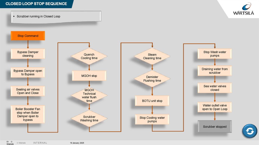
51.
CLOSED LOOP STOP SEQUENCEScrubber running in Closed Loop
Stop Command
Bypass Damper
cleaning
Bypass Damper open
to Bypass
Sealing air valves
Open and Close
Boiler Booster Fan
stop when Boiler
Damper open to
bypass
Quench
Cooling time
Steam
Cleaning time
Stop Wash water
pumps
Draining water from
scrubber
MGOH stop
MGOH
Technical
water flush
time
Demister
Flushing time
Sea water valves
closed
BOTU unit stop
Water outlet valve
open to Open Loop
Scrubber
Washing time
Stop Cooling water
pumps
Scrubber stopped
51 ©
Wärtsilä
© Wärtsilä
I N TE R N A L
19 January 2025
52.
THANK YOU FOR YOUR ATTENTION!Park Myong Gi
Enviro Team MEA
Myong-gi.park@wartsila.com
www.wartsila.com
52
© Wärtsilä
I N TE R N A L
1/19/2025
[Presentation name / Author]
53.
© WärtsiläI N TE R N A L