


")


 Промышленность
Похожие презентации:


Liquefied Gas Tanker Operations - Advanced training program
1. Liquefied Gas Tanker Operations
Advanced trainingprogramme
1
2. Liquefied Gas Tanker Operations
In this session we will study:The products carried
The ships
Basic thermodynamic theory
The legislation
Cargo handling systems
Protective equipment
Cargo handling, change of grades and
measurement
Emergency procedures
2
3. Introduction
The behaviour of water when heated isfamiliar. Similar principles apply to liquefied
gas.
3
4. Basic principles
Gas cargoes are carried in a liquefiedstate
A gas can be liquefied by either
increasing pressure, reducing its
temperature, or a combination of both
The cargo tank must be able to
withstand the pressure of the cargo
4
5. Products
The products most carried are:-
LNG
LPG
Anhydrous Ammonia
VCM, Butadiene, Propylene
Ethylene
5
6. Products
Each product hasits own data
sheet, describing
chemical and
physical
properties,
health data,
emergency
procedures, ...
6
7. Products: LNG
Liquefied NaturalGas (main
element:
methane)
Boiling
temperature:
minus 163°C
7
8. Production of LNG
First removal ofpentanes, then acid
gasses (CO2 and
SO2), which saturates
the gas steam with
water vapour. Then
dehydration, followed
by fractioning
8
9. LNG characteristics
LNG / Methane CH4Boiling point: -163°C
Mol. Weight: 16.04 kg/kmole
Colourless, nearly odourless
Toxicity: asphyxiant, TLV 1000ppm,
odour threshold 200ppm
Main hazard: FLAMMABLE
9
10. Products: LPG
LPG (liquefied petroleum gas) is ageneral expression for propane, butane
or a mixture of both
Produced either from crude oil
processing or as a by-product of
chemical plants
10
11. LPG production
Shown is a simpleflow diagram of
LPG production
11
12. LPG from fractional distillation
1213. LPG products characteristics
Iso-butaneC4H10
Boiling point: -12°C
S.g. 0.58 @ 20°C
N-butane C4H10
Boiling point: -0.5°C
S.g. 0.58 @ 20°C
Mol. Weight: 58.12 kg/kmole
Both products:
Colourless, odourless, usually stenched for
detection (mercaptane)
Toxicity: TLV 600ppm, asphyxiant
Main hazard: FLAMMABLE
13
14. LPG products characteristics
Propane C3H8Boiling point: -42°C
S.g.: 0.58 @ -42°C
Molecular weight: 44.1 kg/kmole
Colourless, odourless, usually stenched for
detection (mercaptane)
Main hazard: FLAMMABLE
14
15. Products: chemical gasses
Most chemical gasses can be producedindirectly from propane
15
16. Products: chemical gasses
Under chemical gasses, or pure gasses,we understand:
Anhydrous Ammonia
Butadiene
Propylene
Ethylene
VCM – Vinyl Chloride Monomer
16
17. Products: Anhydrous Ammonia
Formula: NH3Boiling point: -33°C
S.g. @ -33°C: 0.68
Mol. Weight: 17.03kg/kmole
Main hazard: TOXIC
Colourless, pungent, suffocating odour
Toxicity: TLV 25ppm, Odour threshold 20ppm
Dissolves rapidly in water
17
18. Products: Butadiene
Formula: C H4
6
Boiling point: -5°C
S.g.: 0.65
Mol. Weight: 54.1 kg/kmole
Main hazard: FLAMMABLE and TOXIC
Colourless, mild aromatic, gasoline like
Toxicity: TLV 10ppm, Odour threshold: 1000 ppm,
carcinogenic agent
Need of inhibitor to prevent polymerisation during
transport
18
19. Products: Propylene
Formula:C3H6Boiling point: -47°C
S.g.: 0.609
Mol. Weight: 42.08 kg/kmole
Main hazard: FLAMMABLE
Colourless, faint, gassy, peculiar odour
Toxicity: TLV 1000ppm, odour threshold
unknown
19
20. Products: Ethylene
Formula: C2H4Boiling point: -104°C
S.g.: 0.569
Mol. Weight: 28.05 kg/kmole
Main hazard: FLAMMABLE
Colourless, faintly sweet odour
Toxicity: asphyxiant, TLV 1000ppm, odour
threshold unknown
20
21. Products: VCM
Vinyl Chloride (Monomer) C2H3ClBoiling point: -14°C
S.g.: 0.97
Mol. Weight: 62.5 kg/kmole
Main hazard: HIGHLY TOXIC, FLAMMABLE
Colourless, pleasant, sweet odour
Toxicity: TLV 1ppm, odour threshold 250ppm
Carcinogenic agent
21
22. Products
Most important products in terms oftonnage are:
LNG
LPG products
Anhydrous Ammonia
Other chemical gasses amount only to
small tonnage
22
23. Carriage of cargoes
Pressurized carriage, usually 17 Barg atambient temp.
Refrigerated carriage, at atmospheric
pressure, and at boiling temp.
Semi-refrigerated carriage, at a higher
pressure than atmo, but colder temp.
than ambient
23
24. Vessel types
Fully-pressurized shipsSemi-refrigerated or
semi-pressurized
Fully-refrigerated ships
Ethylene carriers
LNG carriers
24
25. Cargo containment: definitions
Primary barrier is the inner element designedto contain the cargo when cargo containment
system contains two boundaries
Secondary barrier is the liquid resisting outer
element designed to afford temporary
containment of any leakage of cargo from the
primary barrier to prevent the lowering of the
temperature of the ship’s structure to unsafe
level.
25
26. Cargo containment
Five main categories of cargocontainment sytems:
Integral tanks
Membrane tanks
Semi-membrane tanks
Independent tanks
Internal insulation tanks
26
27. Cargo containment definitions: Integral tanks
They form a structural part of the ship’s hulland are influenced in the same manner by
loads, forces and moments
Design vapour pressure normally not above
0.250 barg; if hull scantlings are increased
accordingly, could be increased but not
above 0.7 barg
Can be used for products with boiling point
not below –10°C. (lower temp. On special
27
consideration of the Administration
28. Cargo containment definitions: independent tanks
Independenttanks are completely self
supporting and do not form part of the
ship’s hull
They do not contribute to the ship’s
strength
Depending on the design pressure,
there are three types of independent
tanks: Types A, B and C
28
29. Cargo containment definitions: Membrane tanks
Concept based on very thin primary barriersor membranes supported through the
insulation by the adjacent hull structure.
Must therefore be provided with a complete
secondary barrier to ensure integrity
Design vapour pressure normally not above
0.250 barg; if hull scantlings are increased
accordingly, could be increased but not above
0.7 barg
29
30. Types of vessels and cargo containment
In this section we will detail the typesof vessels, and their association with
different types of cargo containment
30
31. Types of vessels and cargo containment
Pressurized ships, as well as semi-pressurized/semi refrigerated vessels,
always have Type C independent tanks
as cargo containment
Fully refrigerated ships (non LNG)
usually have Type A independent tanks,
but could also carry Type B
independent tanks, or integral tanks
31
32. Types of vessels and cargo containment
LNG tankers can have Membranetanks,Type B independent tanks, semimembrane tanks or in some cases
independent tanks Type A
32
33. Pressurized ships
The cargo is carried in mild steel pressure vesselsdesigned to withstand about 17 bar g
33
34. Pressurized ships
No means of cargo temperature orpressure control is needed
The ships tend to be small, with a cargo
capacity of up to about 3,000 m³
34
35. Pressurized ships
The tanks are normallyType C horizontal
cylinders or spheres, and
no secondary barrier is
required
Double bottom tanks are
normally arranged for
fuel oil and segregated
ballast.
35
36. Fully pressu- rised Gas carrier
Fully pressurised Gas carrierExample of
fully
pressurised
Gas carrier
36
37. Fully pressurised Gas carrier
3738. Semi-refrigerated / semi-pressurized ships
Semi-refrigerated / semipressurized shipsThese ships are larger than the fully pressurised
ships, mostly between 2-15,000 m³, although some
ships are up to 30,000 m³
38
39. Semi-refrigerated / semi-pressurized ships
Semi-refrigerated / semipressurized shipsTanks are bi or tri-lobe tanks, and they
have a MARVS of 5 to 8 barg
39
40. Semi-refrigerated / semi-pressurized ships
Semi-refrigerated / semipressurized shipsProvide a fully-refrigerated capability whilst still
having a design pressure, albeit below that
required for fully pressurised carriage
The number of tanks varies from two for the
smallest, up to six
No secondary barrier is required. The hold
space is normally ventilated with fresh or dry
air
This type of ship often has a reliquefaction
system with a very high capacity
40
41. Semi-refrigerated / semi-pressurized ships
Semi-refrigerated / semipressurized shipsWhile early ships were designed for
temperatures between –10°C and –
33°C, newer semi-pressurised ships are
almost without exception designed for –
48°C to allow fully refrigerated carriage
Use the hull volume more efficiently
(e.g. tapered cylinders, bi-lobed tanks,
transverse tanks)
41
42. Semi-refrigerated vessel
4243. Independent tanks Type C
Type C tanks (also referred as pressuretanks) are normally soherical or
cylindrical and have a vapour pressure
capability of not less than 2 barg
Always used in semi-ref and pressurised
gas carriers
Tanks are subjected to accurate stress
analysis by design
43
44. Independent tanks Type C
Examples of design44
45. Independent tanks
4546. Fully-refrigerated ships
Ships of thefully refrigerated
type generally
have capacities
above
15,000m³, up to
about 85100,000m3
46
47. Fully-refrigerated ships
Normally equipped with between three and sixcargo tanks, extending almost the full beam of
the ship
These ships are designed to carry fully
refrigerated cargoes at near atmospheric
pressure at temperatures down to –50 °C
47
48. Fully-refrigerated ships
Centre bulkhead necessary to preventsloshing
48
49. Fully-refrigerated ships
Prismatic free-standingtanks (Type A) are the
most common
They are supported on
wooden chocks
Tanks are keyed to the
hull to permit expansion
and contraction
49
50. Fully-refrigerated ships
Tanks have an internal centreline bulkheadto improve stability and reduce sloshing
Hold is inerted when flammable cargoes are
carried or filled with dry air for nonflammable cargoes
50
51. Fully-ref Gas carrier
Example of fully refgas carriers
51
52. Independent tanks Type A
Constructed primarilyof plane surfaces
Design vapour
pressure should be
less than 0.7 barg,
this means cargoes
must be carried in a
fully-ref condition
near atmospheric
pressure
52
53. Independent tanks Type A
Self-supporting tankwhich requires
conventional stiffening
To ensure safety in case
of leakage a secondary
containment sytem is
required to protect the
ship’s hull from low
temperatures
Here shown: “conch
design”
53
54. Independent tanks Type A
Example of design54
55. Independent tanks Type A
For a typical fully-ref LPG carrier, thesecondary barrier must be a complete
barrier capable of containing the whole
tank volume at a defined angle of heel
and may form part of the ship’s
structure, if the ship’s hull structure
where cargo may come in contact is
made of special low temperature steel
55
56. Independent tanks Type A
Any secondary barrier must be able to containtank leakage for a period of 15 days
The space between the primary tank and the
secondary barrier is known as the HOLD SPACE
When flammable cargoes are carried these
spaces must be filled with IG to prevent a
flammable atmosphere in the event of tank
leakage
56
57. Ethylene carriers
In appearance this type of ship is verysimilar to the semi-pressurised ship,
and competes for the same cargoes
when the ethylene market is less
profitable
The main difference is the design
temperature of –104°C for the cargo
containment system
57
58. Ethylene carriers
Typically between 2 and 12,000m3Cargo tanks are independent pressure vessel
Type C tanks made from nickel-steel or
stainless steel
No secondary barrier is required
Ships are normally fitted with a double
bottom
cargo tanks normally have a thicker
insulation than on fully refrigerated LPG ships
58
59. Methane/LNG Carriers
Methane/LNG is carried at atmosphericpressure at –163°C in cargo tanks made
from aluminium, nickel-steel or stainless
(austenitic) steel
Insulation is fitted and most LNG ships
are more correctly described as fully
insulated since they usually have no
reliquefaction plant
59
60. Methane/LNG Carriers
Boil-off gas is normally burnt in themain propulsion machinery
Ships are large, mainly from 40,000 to
135,000m3, with four to six cargo tanks
of Type A, B or membrane
60
61. Methane/LNG Carriers
A full double bottom and side ballasttanks are fitted
The space between the primary and
secondary barriers is inerted
61
62. Methane/LNG Carriers Independent tanks Type A
the 'Conch' system aluminium Type Atanks with a treated plywood secondary
barrier and a balsawood/ polyurethane
foam insulation system fitted to the inner
hull
The tanks have centreline bulkheads, with
a common vapour space
62
63. Independent tanks Type B
Type B tanks are designed using modeltests, refined analytical tools and other
methods to determine stress levels,
fatigue life and crack propagation
characteristics
Because of more accurate stress
analysis, only a partial secondary barrier
is required. The cost for R&D is
compensated by the reduced secondary
barrier
63
64. Independent tanks Type B
Mostfrequently we
find type B
tanks of
spherical
construction,
almost
exclusively on
LNG carriers
(MossRosenberg
design)
64
65. Methane/LNG Carriers
Example of MossRosenberg Type
B system
65
66. Methane/LNG Carriers
The Effi Type B (knownas SPB) system selfsupporting prismatic
tanks have a stiffened
plate structure of
aluminium and require
a partial secondary
barrier
66
67. Methane/LNG Carriers
Tanks rest onreinforced plywood
supports which allows
them to expand or
contract freely.
Sloshing is controlled
by a centreline
bulkhead in common
with a transverse
swash bulkhead
67
68. Methane/LNG Carriers
Spherical Type B free-standing low pressuretanks, requiring only a partial secondary
barrier
Moss-Rosenberg system comprises spherical
tanks of aluminium alloy or 9% nickel-steel
with external insulation, supported by
cylinders (or shocks)
68
69. Methane/LNG Carriers
Membranesystems:
“Gaztransport”
or
“Technigaz”
69
70. Methane/LNG Carriers
Gaz-Transport membranes haveidentical primary and secondary barriers
of 36% nickel- steel (or Invar)
Tanks are made from long strakes with
turned-up edges acting as flanges for
welding to the adjacent strake flange
The insulation is perlite in plywood
boxes
70
71. Membrane tanks Gaz transport
0.5mm thick Invarprimary barrier
attached to the inner
cold surface of 200mm
thick perlite-filled
plywood boxes as
primary insulation
71
72. Membrane tanks Gaz transport
Identicalsecondary
barrier with
200mm
perlite filled
boxes for
secondary
insulation
72
73. Methane/LNG Carriers
'Technigaz' membrane systems have aprimary barrier of austenitic stainless steel in
small plates welded together and having
specially shaped orthogonal pressed edges
(or waffles) to allow for expansion and
contraction
Glass fibre aluminium foil (Triplex) membrane
and polyurethane foam insulation
Pronounced chamfer to reduce free surface
and sloshing loads
73
74. Membrane tanks Technigaz
Technigaz features a primary barrier of1.2mm thick stainless steel with rised
corrugations or waffles to allow for
expansion and contraction.
The insulation consists of laminated
balsa wood panels between two
plywood panels
74
75. Membrane tanks Technigaz
7576. Semi-membrane tanks
This is a variation of membrane systemPrimary barrier is much thicker, with a
flat surface and large radius corners
Self-supported empty, but not when
loaded, in that the liquid and vapour
pressure acting on the primary barrier
are transmitted through the insulation
to the inner hull structure.
Rounded parts are designed to
accomodate expansion and contraction 76
77. Secondary barrier requirements: summary
7778. Legislation
Three IMO Codes applicable to gascarriers:
1. 'Code for Existing Ships Carrying
Liquefied Gases in Bulk’ (The
Existing Ships Code). This code
generally applies to ships delivered
before 31st December 1976.
78
79. Legislation
2. 'Code for the Construction andEquipment of Ships Carrying
Liquefied Gases in Bulk (the GC
Code). This code generally applies to
ships built on or after 31st December
1976 but prior to 1st July 1986.
79
80. Legislation
3. 'International Code for theConstruction and Equipment of
Ships Carrying Liquefied Gases in
Bulk' (IGC Code). This code is
mandatory under the provisions of
Chapter VII of the 1974 SOLAS
Convention. It applies to ships the keels
of which are laid on or after 1 st July
1986.
80
81. Legislation
The IMO Codes are intended to producea common set of regulations, allowing a
ship to be issued with a Certificate of
Fitness indicating compliance with the
Code
As with other certificates, the Codes
require periodic re-inspection during its
lifetime to maintain validity.
81
82. Legislation
The Gas carrier codes amplify theprovisions of Chapter VII of the SOLAS
convention as well as Annex II of
Marpol
Other conventions and regulations
(international, flag state and class) are
of course applicable to Gas carriers, i.a.
SOLAS, MARPOL, STCW, ...
82
83. Ship types
Following types of ship acc. to survivalcapability:
Type 1G, intended to carry products which
require maximum preventive measures to
preclude the escape of the cargo
Type 2G, for products, which require
significant preventive measures (...)
Type 3G, for products which require
moderate preventive measures (...)
83
84. Ship types
Also, type 2PG, which is a gas carrier ofmax. 150m, with independent type C
tanks, for a MARVS of at least 7 barg
and a system design temp of –55°C or
above
84
85. Ship types
As a summary:Type 1G gas carriers are intented for
products with the greatest overall
hazard and types 2G/2PG and 3G for
products with progressively less hazard
Type 1G should survive the most severe
standard of damage
85
86. Type 1G, location of cargo tanks
8687. Type 2G/2PG and 3G, location of cargo tanks
8788. Ship design and cargo containment
The Gas codes establish a standard forthe contruction, and equipement of gas
tankers
Chapter 19 of the Codes gives a
summary of the requirements per
product
88
89. Ship design and cargo containment
8990. Ship arrangements
Gas dangerous spaces:Cargo pump and compressor rooms
Hold spaces
Cargo containment system and piping
Spaces in cargo area, which are not equipped
to ensure that their atmo is safe at all times
Enclosed spaces outside of cargo area,
through which piping passes,...
90
91. Ship arrangements
Gas dangerous zones:Open deck zone within 3 m of any cargo tank,
piping,...
Open deck over cargo areas up to 2.4m
above weather deck
Compartment for cargo hoses
Enclosed or semi-enclosed space having a
direct opening to any gas dangerous zone or
space.
91
92. Ship arrangements
9293. Ship arrangements
A gas safe space is a space other than agas dangerous space
Windows facing the cargo area (and the
sides on 3m) should be of the fixed
type
All air intakes should be equipped with
closing devices
93
94. Ship arrangements
Access from agas dangerous
zone to a gas
safe place
should happen
through an air
lock
94
95. Ship arrangements
Airlocks:ventilation should be of the positive-pressure
type
upon lost of over pressure in the space, the
non-certified safe type electrical equipment
should be de-energised
doors should be self closing and without
arrangements that they could be held open
Doors fitted with an alarm audible and visual,
to warn both sides if a door is opened
95
96. Ship arrangements
Gas-safe spaces in the cargo area should befitted with a positive pressure ventilation
system
Gas dangerous spaces should be fitted with
a negative pressure ventilation system
Ventilation exhaust ducts from gas
dangerous spaces should discharge upwards
at least 10m horizontally from intakes to gas
safe spaces
96
97. Ship arrangements
Ventilation arrangement of a deck-house97
98. Basic thermodynamic theory
Pressure:Pressure gauges normally read pressure
above or below atmospheric pressure, i.e.
relative pressure or gauge pressure (unit:
N/m² or barg)
Absolute pressure: the sum of gauge and
atmospheric, i.e. The zero is equivalent to the
pressure of any substance at absolute zero
temperature
98
99. Basic thermodynamic theory
Ideal gas lawsAn ideal gas is one which would obey
the gas laws exactly by virtue of its
molecules being so far apart that they
exert no force on one another
No such gas exist, but most gasses
approach the ideal closely enough for
most purposes
99
100. Basic thermodynamic theory
Boyle’s LawAt constant
temp., the
volume of
a given
mass
varies
inversely to
its absolute
pressure
100
101. Basic thermodynamic theory
Charles’ lawThe volume
of a given
mass of gas
at constant
pressure
varies in
proportion
to its
absolute
temp.
101
102. Basic thermodynamic theory
The pressurelaw
At constant
volume the
pressure of
a given
mass of gas
varies
directly with
its Kelvin
temp.
102
103. Basic thermodynamic theory
If we combine the three gas laws wefind the general gas equation
103
104. Basic thermodynamic theory
General Gas equation:pV=nRT
Where: P (Pa), V (m³), T (°K)
And n= M/m,
M being the mass of gas (kg) and m, the molecular
weight
R is the universal gas constant
= 8.314 J/kg mole °K
104
105. Basic thermodynamic theory
Dalton’s LawThe total pressure of a mixture of
different gasses in a space is the sum of
the pressure each gas would exert if it
occupied the space alone at the
temperature of the mixture
105
106. Basic thermodynamic theory
Jules’ lawThe internal energy of an ideal gas
depends only on its temperature and is
independent of changes in pressure and
volume
Therefore, if P and V change, the
energy of the gas remains constant
unless its temperature changes
106
107. Basic thermodynamic theory
The total heat content of a substancedepends on its temperature (or internal
energy), its volume and its pressure: this
quantity is known as the enthalpy of the
substance
When heat is applied to or removed from a
substance, the heat involved divided by the
temperature of the substance is called its
entropy
107
108. Basic thermodynamic theory
The enthalpy is equal to the sum of internal energy ofa liquid/vapour system plus the external work
performed i.e. The product of the pressure-volume
work done on the system:
H = U + pV
Where H - enthalpy (kJ/kg) and U – internal energy
(kJ/kg)
The pV term represents the energy available within the
system due to its pressure and volume
108
109. Basic thermodynamic theory
Absolute value of enthalpy is of no practicalinterest
The changes of enthalpy are important in the
thermodynamical analysis of a process
The most widely used presentation of
enthalpy changes is that of the Mollier
diagram
Mollier diagrams are available for many
substances and are available on board of gas
carriers for the usual gasses
109
110. Basic thermodynamic theory
110111. Basic thermodynamic theory
Let us again summarize the behaviour ofwater
When ice is heated, its enthalpy (H) and
temperature (T) increase until it melts.
The initial temperature rise involves the
absorption of sensible heat and melting
absorbs the latent heat of fusion.
111
112. Basic thermodynamic theory
When water is heated, absorbingsensible heat, its saturated vapour
pressure (P) increases until, at
saturation temperature, it reaches the
pressure on the liquid surface. The
water then absorbs the latent heat of
vaporisation and boils.
The saturated vapour absorbs more
heat and becomes superheated
112
113. Cargo handling systems
In this chapter we will study:Cargo piping
Cargo valves
Cargo hoses
Cargo venting system
Cargo pumps
Heat exchangers
Reliquefaction systems and control of boil-off
Instrumentation and auxilliary systems
113
114. Cargo piping
Piping systems for cargo vapour and liquid to fulfillthe following requirements:
1. segregated from other piping systems, except
where temporary interconnections may be
required, i.a. for purging, inerting,...
2. Should not pass through a not-cargo-related
space, i.e. accomodation, machinery space other
than cargo compressor room etc...
114
115. Cargo piping
3. Connected to the cargo containmentsystem directly on open deck
4. Located in the cargo area above deck
5. Located inboard of the transverse
tank location
115
116. Cargo tank piping
116117. Cargo piping
117118. Cargo piping
118119. Cargo piping
Strainers ( filters ) are commonlyinstalled in the system to protect the
cargo handling equipment from
damaging by foreign objects i.e. at
manifold connections and before
entering cargo tanks
119
120. Cargo valves
For cargo tanks with a MARVS notexceeding 0.7 barg, all liquid and
vapour connections should have shutoff
valves located as close to the tank as
possible.
Valves may be remotely controlled but
must always be provided with local
manual shutoff
120
121. Cargo valves
One or more ESD valve, remotely controlled shouldbe provided for shutting down cargo transfer
between ship and shore
Tanks with MARVS > 0.7 barg, should have manual
stop valve and remotely controlled shutdown valve
in series, as close to the tank as possible
Review of port and terminal regulations
Ship regulations and emergency procedures
All other elevant info
Safety checklists should be completed following
guidelines
121
122. ESD valves
ESD valves are to close in a timebetween 20 and 30 seconds in order to
avoid pressure surges in the piping
system
122
123. Types of valves
Normally on gascarriers, we find
ball, globe, gate
or butterfly valves,
though most
valves relating to
cargo will be of
the ball or
butterfly type.
Example of ball
valve:
123
124. Types of valves
124125. Cargo hoses
Cargo transfer may be done intoloading arms or through the use of
cargo hoses or both.
Hoses should be tested yearly at 2.5
times the max. Working pressure and
should be designed to withstand 5
times that pressure
125
126. Cargo hoses
Usually stainless steel hoses reinforcedwith woven stainless steel braid are
used
Proper handling of the hoses is critical
in order to avoid premature failure.
126
127. Cargo hoses handling
127128. Cargo hoses handling
128129. Cargo hoses handling
129130. Pressure relief system / ventilation
Pressure relief system should be connected to avent piping system, i.e. Vent masts, as to
minimise the possibility of cargo vapour
accumulating on the decks or entering
accomodation spaces, etc...
Each cargo tank should have at least 2 pressure
relief valves of equal capacity
Setting of safety valves should not be higher
than the max. design pressure of the cargo
tank (= MARVS)
130
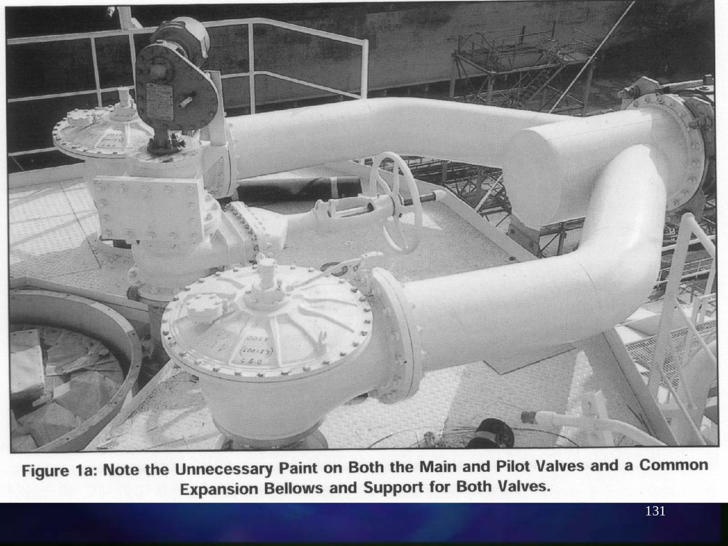
131.
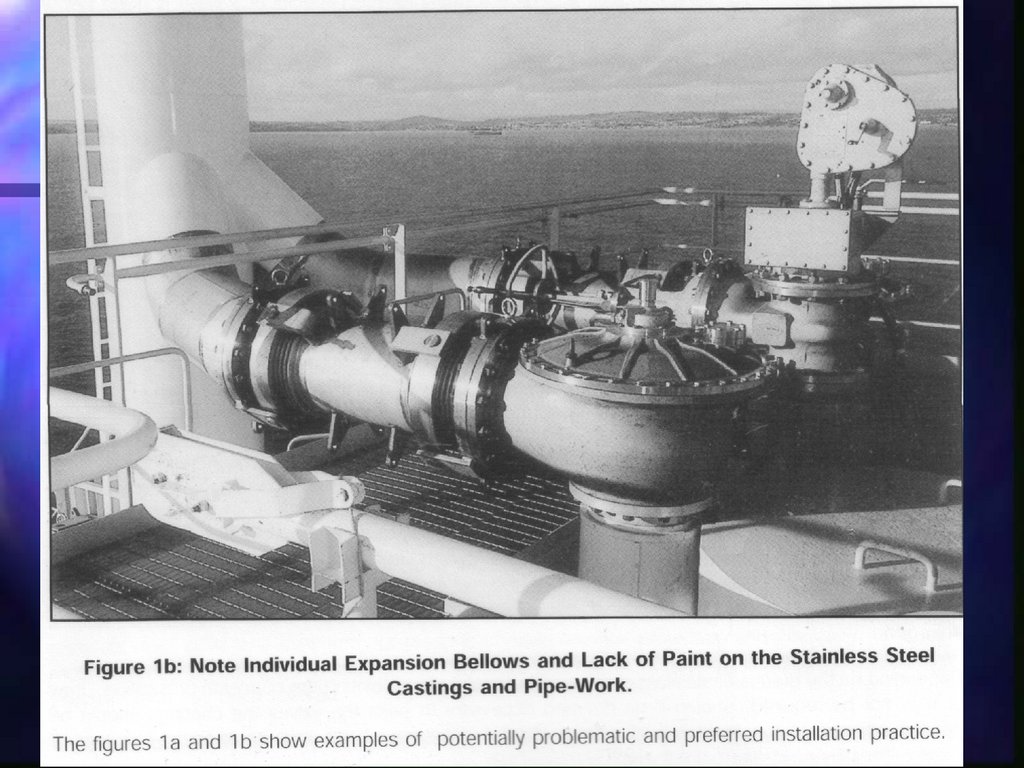
131132.
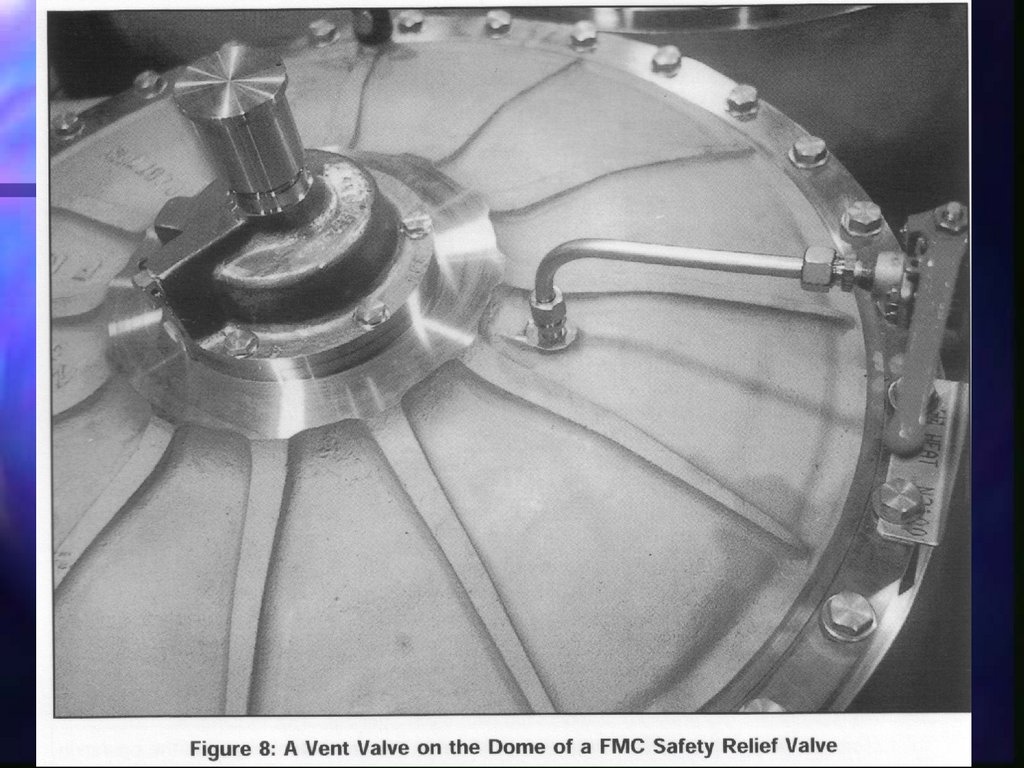
132133.
133134. Pressure relief system
Schematicdiagram of a
pressure
relief
system
134
135. Pressure relief system / ventilation
Safety valves should be fit for cold serviceHeight of vents not less than 6 m above deck
and at least 25m from the nearest air intake
Separate pressure relief systems for separate
cargoes
Vent masts should be fitted with means of
liquid draining
Flame screens on vent outlets
135
136. Pressure relief valves
Spring loaded type136
137. Pressure relief valves
A cargo tanksafety relief
valve, pilot
operated
137
138. Pressure relief valves, pilot op.
Operationalprinciples:
1. Position
closed
138
139. Pressure relief valves, pilot op.
Operationalprinciples:
2. Position pilot
open
139
140. Pressure relief valves, pilot op.
Operationalprinciples:
3. Position
open and
flowing
140
141. Pressure relief system
Type C tanks and/or hold spaces maybe fitted with bursting disks
All pipelines which may be isolated
when full of liquid must be provided
with safety relief valves
141
142.
Pressure relief systemSome relief valves have different settings.
A proper record must be kept of any changes
in the pilot valve spring (e.g. for harbour or
sea condition or for different cargoes) and
posted in the CCR
on Type `C‘ tanks, they can be adjusted to
permit a means of reducing the MARVS to
comply with United States Coast Guard
(USCG) regulations . These regulations
impose more stringent safety factors for
pressure vessel design than do the Gas Code
requirements.
142
143. Vacuum protection
Required for most tanksTwo independant pressures switches to
stop cargo pumps and reliquefaction
units
Vacuum relief valves are permitted and
should admit IG, cargo vapour or air to
the tanks
143
144. Rollover
Temperature related problemEspecially in LNG shore tanks
Sudden evaporation, eventually over
capacity of relief valves
Dangerous when at anchor for longer
periods
Same problem when mixing propane
and butane together in ships cargo tank
144
145. Cargo pumps: pump types
145146. Cargo pumps
The unloading of liquefied gas is done by one,or a combination of the following methods:
Submerged centrifugal pump
Submerged centrifugal pump and a booster
pump on deck
Submerged eductor
Pressurizing and a deck mounted cargo pump
pressurizing
146
147. Cargo pumps
Deepwellpump
arrangement
147
148. Deep-well pumps
Shaft sealingconsists of a
double mechanical
seal with an oil
flush
148
149. Deep-well pumps
Pumpperformance
curves for a
typical
deepwell
pump
149
150.
Deep-well pumpsNPSH : gas is always at its boiling point.
if cavitation is allowed to occur the
impeller and the shaft bearings will
damage quickly.
Possible solution : increase tankpressure
150
151. Deep-well pumps
Pumpcharacteristics for
different s.g.
of liquid
NH3 - VCM
151
152. Submerged pumps
This type of pumps isused on LNG carriers
and on many large
LPG carriers
152
153. Submerged pumps
Pumps and motorsare cooled and
lubricated by the
pumped cargo and
are thus susceptible
to flow rate
damage
153
154. Booster pumps
Pumps mounted on deck to work inline with the regular cargo pump in
order to discharge the cargo
against high back pressure and/or,
for ref. cargo, through a cargo
heater at higher than boiling temp.
into pressurized tanks
154
155. Booster pumps
System characteristics of parallel pumpsworking in series with a booster pump
155
156. Booster pumps
156157. Automatic control and protection
For safety and to protect the cargo pumps,they are equipped by one or all following
shutoff devices
Differential pressure gauge
Ammeter
Float gauges
Flow switche
ESD
Low tank pressure
157
158. Ice prevention
enter cargo pumps, block lubricatingpassages, unbalance impellers and seize
bearings.
a small quantity of freezing-point
depressant
When deepwell pumps are not in
operation, manual rotation of the shafts be
carried out during cool-down and loading
to prevent freezing of the impellers.
158
159. Eductors
159160. Eductors
Mostly used as an emergency system orfor hold-space bilge system
160
161. Eductors
Hold space bilgesystem
161
162. Heat exchangers
Heat exchangers may be used for anumber of purposes:
Heaters of liquid cargo
Vaporizers of liquid cargo
Dryer of air and inert gas
Coolers for lube oil and glycol
Condensers and intercoolers in a
reliquefaction plant
162
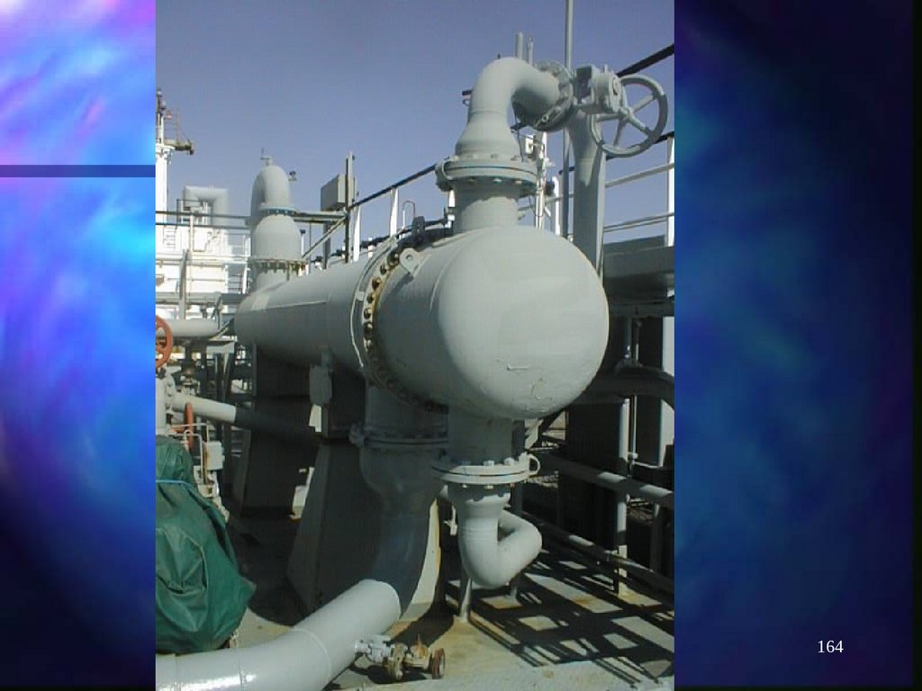
163. Cargo heaters
Used to discharge fully or partrefrigerated cargoes into pressurised
shore tanks (in conjuction with booster
pumps if necessary)
163
164.
164165. Cargo heaters
165166. Cargo heaters
to avoid low-temperature embrittlementof the shore tanks and pipelines .
Fitted with temp and press control
equipment to prevent freezing
Normally designed to raise temperature
from –45°C to –5°C
166
167. Vaporisers
Used as a means of providing cargovapour from available liquid, i.e. during
gassing-in operations, or during
discharge operations in order to
maintain tank pressure
Usually steam vaporisers, horizontal or
vertical but often cargo heaters or
condensers can be used as vaporisers
as well (sea water)
167
168. Vaporisers
168169. Air dryers
Air dryers are used to reduce the dewpoint of the atmosphere in the cargo
tank (dry air) during change-over
operations (from one cargo to
another cargo) by passing ambient air
through freon condensors or through
cooling tower filled with silica-gel
169
170. Air dryers
170171. Glycol systems
A glycol system is installed on gas carriers. Itis used:
As a cooling system for cargo compressor bearings
As a cargo compressor suction gas superheating
unit in order to prevent pre compression
condensation
As compressor lube oil heating to vaporize
refrigerant which may contaminate the oil
(...)
171
172. Glycol systems
(...)For cargo compressor cylinder head cooling
For cooling at two stage compression
intercoolers
The use of glycol prevent freezing of
the medium due to the very low
working temperatures it may be in
contact with
172
173. Glycol systems
173174. Inert Gas
Composition of IG produced by an IGgenerator:
Approx. 84% Nitrogen
Approx. 0.5% Oxygen
Approx. 15% Carbon Dioxide
Approx. 0.5% Carbon Monoxide, Oxides of
Nitrogen and Sulphur Dioxide
174
175. Gauging systems
IMO requires every cargo tank to be fitted byat least one liquid level gauge
Most common type is closed and restricted
system, with float, Nitrogen bubble gauges,
differential pressure gauges, ultrasonic
gauges or slip tubes
Gauging on a gas carrier shows innage, unlike
for other tankers where ullage is measured
175
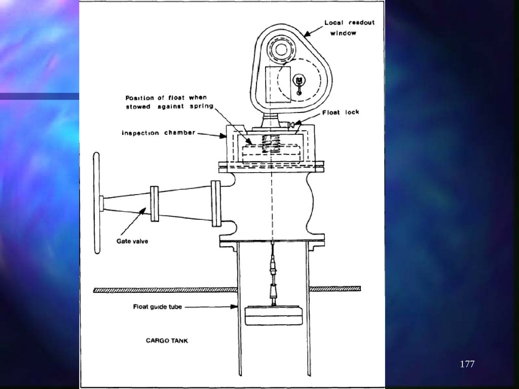
176. Float gauge
Widely used in all tanker workConsists of a float attached by a tape to
an indicating device
Float must be lifted from the liquid
when not in use
176
177.
177178.
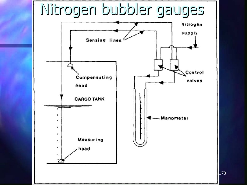
Nitrogen bubbler gauges178
179. Nitrogen bubbler gauges
Measures the pressure necessary to displacethe liquid inside a small bore tube mounted
vertically in the tank
Enough nitrogen is introduced into the tube
to displace the liquid and just begin to bubble
at the bottom
The pressure necessary to do this is
measured and is a function of the liquid level
and the density
179
180.
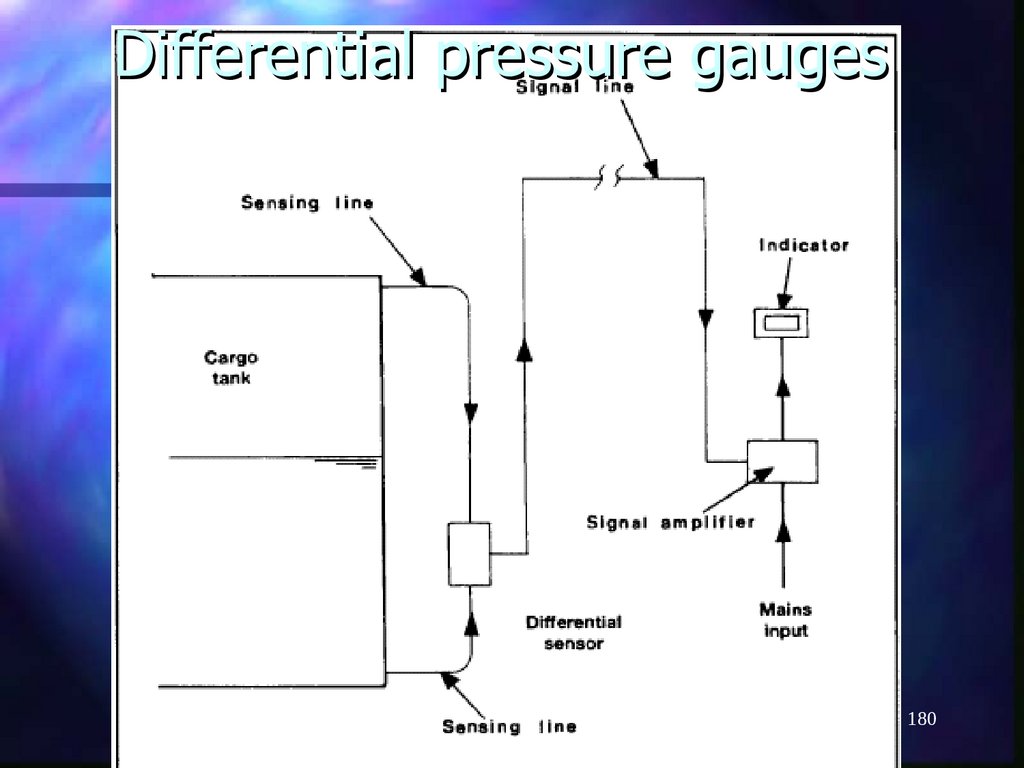
Differential pressure gauges180
181. Differential pressure gauges
Generally only found ashore or decktanksOperates on differential pressure between
liquid and vapour phase
Signal lines for the instrument are purged
with IG or Nitrogen
181
182.
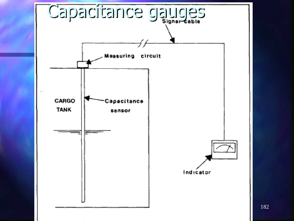
Capacitance gauges182
183. Capacitance gauges
Measures the change in electricalcapacitance between two probes as
cargo liquid rather than vapour takes up
the space between them
Electrical circuit are of course made
intrinsically safe
183
184. Ultrasonic gauges
184185. Ultrasonic gauges
Operates like an echosounderMeasures the liquid depth by reflecting sound
waves from the liquid/vapour interface
Ultrasonic gauges fitted on gas carriers can
be unreliable due to boiling of the liquid
Advantage
no influence by the gas atmosphere
you do not need openings in the containment
185
186.
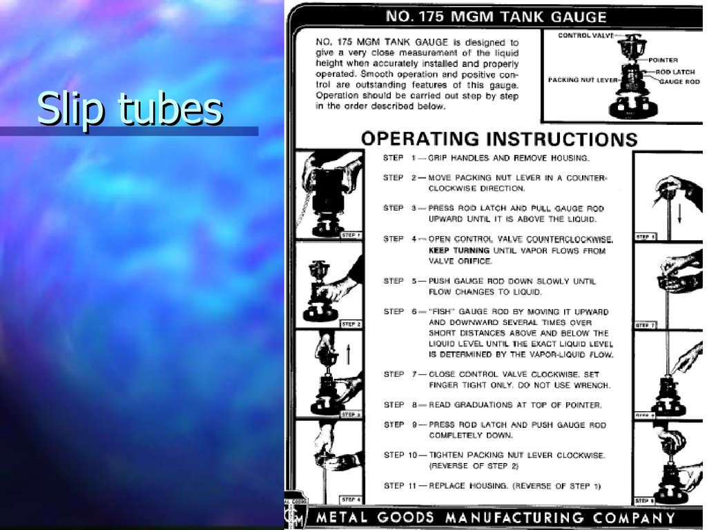
Slip tubes186
187. Slip tubes
Restricted type since a small amount of cargois released during measurement
Operates on basis of a sliding tube
penetrating the tank top
Tube is glanded at the top and can be
lowered or raised
Liquid or vapour issuing from the orifice gives
an indication of the liquid/vapour interface
Only type C tanks
187
188. Pressure monitoring
IMO requires a pressure monitoringsystem throughout the cargo system,
incl. Cargo tanks, pump discharge lines,
liquid and vapour crossovers, etc...
Pressure switches are fitted to various
components to operate alarms and
shutdown systems
188
189. Pressure monitoring
Vapour space of each cargo tank shouldbe provided with a pressure gauge
Max and min allowable pressure should
be marked on the gauges
Alarms should be activated before set
pressures are reached (pre-alarms)
189
190. Temperature monitoring
IMO requires each cargo tank to befitted with at least two devices for
indicating cargo temperature, placed
one at the bottom of the tank the other
at the top
Should be marked for lowest admissible
temp.
190
191. Temperature monitoring
Usually in cargo tanks, thermometersplaced as follows:
Cargo tank hull temperature at sump
Bottom
mid (50% of level)
Top (98% of level)
Tank dome (vapour space)
191
192. Level alarms
Each cargo tank should be fitted with ahigh level alarm operating independently
of liquid level indicators (High level –
around 97%) and giving audible and
visual warning
Another independent sensor should
automatically activate shutoff to prevent
the tank from overfilling - ESD (Very high
level –98.5%)
192
193. Gas detection system
Every gas carrier should be fitted with afixed gas detection system
Audible and visual alarms located on the
bridge, in the cargo control room and at
the gas detector readout location
193
194. Gas detection system
Detection of gas should be fitted in:Cargo compressor rooms
Motor rooms for cargo machinery
CCR
Enclosed spaces within the cargo area, including
hold spaces
Ventilation hoods and gas to E.R. Supply ducts
(LNG)
Air locks
194
195. Gas detection system
195196. Gas detection system
Sampling and analysing from eachdetector head is done continuously and
sequentially.
Time between two scans of the same
zone not to exceed 30 minutes
Vent hoods and gas ducts of LNG
carriers to be scanned continuously
196
197. Gas detection system
For all spaces, alarms should beactivated for flammable products when
vapour concentration reach 30% of the
LEL
Hold spaces and interbarrier spaces
should be provided with sampling points
(top and bottom) by means of portable
equipment (toxic gasses)
197
198. Gas detection system
Every ship should be provided with atleast TWO portable sets of gas
detection equipment suitable for the
products carried
Fixed gas detection equipment should
be calibrated before each arrival in port
and/or before each cargo operation
198
199. Water spray system
A water spray system should beinstalled to cover:
Exposed cargo tank domes
Exposed on deck storage vessels for
flammable or toxic gasses
Liquid and vapour manifolds and the area
of their control valves
Boundaries of superstructures, of
compressor room, motor room
199
200. Water spray system
At least 10 l/m² per minute forhorizontal surfaces and at least 4 l/m²
per minute for vertical surfaces
200
201. Water spray system
201202. Emergency Shut Down system
202203. Emergency Shut Down system
Manually operated (pneumatic or electric) andautomatically for some functions (eg very high level
in cargo tank)
Also required to be automatic upon loss of electric
control or valve actuator power.
at tank domes or cargo manifolds (where fusible
elements are situated)
All valves should be ‘fail-safe’ type
Shuts down cargo pumps, compressors, ventilation
of compressor room and closes Esd valves
(manifold and tanktop)
203
204. Cargo handling operations
We will study:Preparation for loading and loading
Cargo measurement and calculations
Cargo condition maintenance on passage
and in port
Preparation for unloading and unloading
Changing cargoes
204
205. Preparation for loading
Let’s assume a cargo tank is clean andcontains air and we need to proceed for
loading
Sequence of operations:
Drying
Inerting (if necessary)
Purging (or gassing-up)
Cool-down
Loading
205
206. Drying
Removing moisture from cargo tankand pipe work
Reducing dew point of tank atmosphere
Minimising potential ice formation
process
Usually dew point of up to –50°C
206
207. Inerting
Reduce oxygen content in the cargosystem
Prevent flammable atmospheres to be
created
Not to be done with NH3
207
208. Purging
To replace inert gas in cargo tanks withvapours of the cargo to be loaded
Prepare tanks for loading cargo
Cargo vapour may be taken from a
shipboard tank via a vaporiser or from
shore
Purging is done by displacement so care
should be taken to create a good buffer
208
209. Purging
Displacement method is used fordrying, inerting or purging
Buffer is critical
Inert / vapour interface should be
rather homogene and progress of the
buffer can be followed in the tanks by
regular sampling
209
210. Purging using vapour from shore
210211. Cooldown
Before loading a refrigerated cargo,tanks must be cooled down in order to:
prevent thermal stresses
Prevent excessive tank pressure during
loading
211
212. Cooldown
Rates at which cargo tank can becooled down depend on design but
typically we find a max of 10°C per
hour (check company’s instructions and
loading manual)
Cooling down can be done with liquid
from shore, from deck tank or by using
reliquefaction plant, or a combination
212
213. Cooling down, using liquid from shore
213214. Cooldown
Liquid is sent to top spray of line of thecargo tank
Droplets evaporate and take away
energy from the tank atmosphere thus
cooling down
Pressure rises in tank, so the use of the
reliquefaction plant is necessary unless
we are using a vapour return to shore
214
215. Cooldown
Cooldown should continue until liquidcollects at the bottom of the tank and
bottom temp is max.:
LNG:
- 160°C
Ethylene: - 103°C
Ethane: - 87°C
Propane: - 41°C
NH3:- 31.5°C
215
216. Cooldown
During cooldown, valves should beoperated frequently to ensure that they
are free
Pump shafts should be turned manually
at regular intervals
216
217. Cooldown
The thermal contraction of the cargotank may cause a pressure reduction in
the hold spaces
Dry air or inert gas or dry nitrogen
(LNG) should be introduced as
necessary
217
218. Preparation for loading
In port following notice should always beposted, shore side by the accomodation
ladder, sea side amidships
218
219. Preparation for loading
When the liquefied gases being handledpresent a health hazard, further notices
in appropriate languages should be
prominently displayed stating:
219
220. Preparation for loading
ESD should be tested before eachoperation
Ventilation of accomodation spaces
shall be set in recirculation mode
Drip tray at manifold shall be prepared
and filled with sea water , if applicable
220
221. Loading with vapour return
221222. Loading without vapour return
222223. Receiving warm cargo
When loading a cargo at a tempresulting in a vapour pressure
exceeding MARVS of cargo tanks,
loading rate will depend on:
The capacity of the reliquefaction plant and
compressors (kcal/hour)
Capacity of terminal’s compressors and
R.P. in case a vapour return is being used
223
224. Loading rate vs. Reliquefaction plant
Loading rate for a warmer than boilingpoint cargo can be calculated:
Example: How many tons NH3 can we
accept per hour if loading temp is –20°C, 3
compressors available and SW temperature
is 20°C?
1. MARVS 440mBar, for safety we take
max. Tank pressure 350 mBar
224
225. Loading rate vs. Reliquefaction plant
2. Liquid density tables: NH3350mBar corresponds to –27.5°C (max temp we can
allow in the cargo tanks)
3. We must bring cargo from –20°C to –27.5°C
via R.P. and condensors
4. Properties of NH3:
-20°C corresponds to 78 kcal/kg
-27.5°C corresponds to 70 kcal/kg
We must take 8kcal/kg with our R.P.
225
226. Loading rate vs. Reliquefaction plant
5. From loading manual, we find thatfor NH3 and SW 20°C 1 condensor
capacity is 184,000 kcal/hour
3 x 184,000 / 8 = 69,000 kg/h
Our max loading rate is 69 mT/h
226
227. Cargo tank filling limits
IMO Gas code specifies maximum filling limitsas follows:
Vl = 0.98 V dr/dt
V is the max volume to which the tank can be
l
loaded at ref temperature
V is the total volume of the tank
D is the density of the cargo at ref temperature
r
D is the density of the cargo at the loading
t
temperature
227
228. Cargo tank filling limits
Example:Fully ref vessel loading propane at –42°C Relief
valves set at 0.25bar
Absolute pressure: 0.25+1.0=1.25 bar
Ref temperature (corresponding to SVP 1.25 bar for
propane) = -37°5C
Density of liquid propane d = 0.5765 @ -37°5C
r
Density of liquid propane d = 0.582 @ -42°C
t
V =0.98 V 0.5765 / 0.582 = 0.97 V
l
Thus tanks can be filled to 97%
228
229. Cargo tank filling limits
Membrane tanks have special loadingconditions in order to minimize sloshing
forces in heavy weather
Filling limit usually 99% of tank volume
229
230. Cargo quantities
Liquefied gas cargoes are carried as:boiling liquids in equilibrium
with their vapour in closed containment
systems
The vapour phase above the liquid
cargo must be calculated and included
in the total cargo quantity
230
231. Cargo quantities
On discharge one normally retainssufficient cargo on board to keep the
tanks cooled before the next loading
One always calculates cargo quantities
both before and after loading and
discharge operations in order to
ascertain the quantity loaded or
discharged
231
232. Cargo quantities
Innage orsounding is
measured as
opposed to
ullage on
other tankers
232
233. Cargo quantities
A calibration table is provided for each cargotank
They are calculated for
ambient temperature
the vessel being in upright position
for no trim
Therefore certain corrections must be applied,
together with others, for temperature variation
233
234. Cargo quantities
Corrections:Trim correction
List correction
Tape correction
Float correction
Shrinkage of tank shell
234
235. Corrections
Tape correction:The float gauge tape passes through the
cold vapour space
Depending on the temperature it will
contract
It will therefore indicate a lower liquid level
then actually present
Tape correction should be added to the
liquid level read
235
236. Corrections
Float correction:The zero of the float gauge is determined
by the manufacturer but is normally at
50% of float immersion
Cargo temp and density is different from
that assumed by the manufacturer’s zero
determination
A small correction for float immersion is
required
236
237. Corrections
Shrinkage factor:The cargo tank is calibrated at ambient
temperature
If cold cargo is loaded the tank will have a
smaller volume
Different corrections are applied to liquid
and vapour phases because of different
temperatures
237
238. Cargo calculation sheet
238239. Cargo calculation sheet
239240. Cargo condition maintenance
Refers to:The cargo quantity is maintained without
undue losses during sea passage (halfpercent loss clause in c/p)
The cargo tanks pressures are maintained
within design limits
The cargo temperature is maintained or
changed as required (c/p)
240
241. Cargo condition maintenance
Boiloff must be removed to maintainequilibrium
Three methods:
For LNG, it is supplied to the boilers and burned as
fuel (or possibly used directly in dual-fuel diesel
engines)
For LPG ships, it is reliquefied and then returned
to cargo tanks via condensate lines
Excess gas can be vented to the atmosphere
(substantial loss of cargo)
241
242. Reliquefaction system
Should be able to keep the liquid eitherat loading temperature or cool it down
to boiling temperature
Cooling down rate depends on the
capacity of the plant. usually a ship is
able to bring the temperature of her
cargo down 1°C in between 12 and 48
hours.
242
243. Cargo conditioning (loaded)
243244. Preparation for unloading and unloading
Several methods of dischargingdepending on ship type and terminal
type:
Pressure discharge
Pressure and booster pump discharge
Centrifugal cargo-pump discharge
Centrifugal cargo-pump and booster pump
discharge (in line)
244
245. Unloading
Unloading can happen:with vapour return, or
without vapour return in which case liquid
cargo must be evaporated and sent to the
cargo tanks in order to:
keep tank (over)-pressure and
replace the liquid volume being discharged
245
246. Discharge precautions
Function test of pumps and valvesFunction tests of instruments for
measuring pressure, temp and cargo
level
Function test of fixed gas detection
equipment
Cargo calculation and sampling if
requested
Line up inspection for discharging
246
247. Discharge precautions
If needed pre-cool ship’s cargo linesStart discharging slowly and carefully to
avoid thermal stresses on board and
ashore
Check for leakage in cargo system
Control tank pressure during discharging
Control ship’s stability regularly
247
248. Pressure discharge
Alternative or additional to use of cargopumps
Inefficent method, slow and restricted
to small type C tanks
Liquid is transferred ashore by
increasing pressure in cargo tank
(above liquid)
248
249. Centrifugal cargo pump discharge
Discharge rate should not be reduced toaccomodate terminal needs, by
throttling manifaold valve (in order to
avoid heating the cargo)
Pump throttling valve or partial
recirculation of cargo should be used
249
250. Centrifugal cargo pump discharge
If cargo is to be discharged fully ref,pumps will be used in parallel in order
to increase rate to shore’s request
Pressure in cargo tank will fall and
should be kept above minimum by
sending cargo vapour to tanks, either
from a vapour return or by evaporating
liquid cargo
250
251. Discharging without vapour return
251252. Centrifugal cargo pump discharge
If discharge is to happen into apressurized/ambient temp tank ashore,
the cargo should be unloaded via a
booster pump in serie with cargo pumps
and via a cargo heater
252
253. Booster pump discharge
253254. Changing cargoes
Before changing cargo grades:Important to remove all liquid residues
from the cargo system
Depending on design of ships, liquids
can be removed by pressurising, normal
stripping or by heating the tanks with
Hot Gas from the compressor
254
255. Removal of liquid residue by pressurisation
255256. Removal of liquid residue by hot gas
256257. Warming up
Warm up progressively in view of ventilatingtanks with fresh air for inspection, dry dock
or cleaning
Warm up to prevent condensation and to
remove possibility of reliquifying cargo
Warming up by using hot gas
Essential operation for LNG vessels (very
progressive and slow warm up)
257
258. Inerting
Reducing the oxygen content to preventcreation of explosive mixtures in tanks
Dewpoint of IG very low
No inerting after NH3
Usually by displacement, but on
pressure ships, can be done by dillution,
dillution and pressurising or dillution
and vacuum
258
259. Inerting
259260. Aerating
260261. Summary
1.2.
3.
4.
5.
Remove any cargo liquid residue
Warm up the tank
Purge the cargo vapour with inert gas
Ventilate the tanks until 21% oxygen
reading is obtained
As discussed, the procedure is
different with Ammonia due to the
inherent properties of the product
261
262. Reliquefaction and boil-off control
Boil-off generated during the voyage would giverise to excessive cargo tank pressure if allowed to
accumulate.
Three alternative methods of dealing with boil-off:
LNG, the cargo can be supplied to boilers and burned
as fuel
LPG can be reliquefied by the reliquefaction plant on
board and then the condensate returned to the cargo
tanks
Venting, but this is not economically viable (loss of
cargo)
262
263. LNG Boil-off control
In the case of LNG carriers boil-off isused as fuel in the ship’s boilers or gas
turbines
263
264. LNG Boil-off control
264265. LPG/Chem Gas Reliquefaction
In this case, boil off vapours are compressedthen cooled in condensers, where they
become liquid. Expanding this liquid provides
the drop in temperature to allow boil off to
be returned to the tank at required
temperature
265
266. Reliquefaction plant
The plant is designed to perform following operations:Cool down the cargo tanks and associated piping before
loading
Reliquefy the cargo vapour
Maintain or reduce cargo temperature
The plant capacity is designed to maintain the cargo
temperature at a level such that the pressure does
not exceed the relief valve setting under the most
extreme service conditions, usually taken as 45°C air
and 32°C sea temperatures
266
267. Reliquefaction plant
Spare capacity at least equal to the largest singleunit has to be provided.
In most cases the stand-by capacity is a complete
unit including compressors with their driving
motors, heat exchangers, control systems and
piping, though this is in excess of the minimum
requirement of the IMO Codes.
If additional capacity is provided in the form of an
independent unit, this can be used to increase the
rate of cool down, or to reliquefy boil-off during
loading.
267
268. Reliquefaction plant
On semi-pressurised ships, the cargocompressors can raise the tank
pressure enough to prime deckmounted discharge pumps prior to
discharge
Cargo vapour is drawn off and
compressed, and the hot gas
discharged is returned to the cargo tank
268
269. Reliquefaction plant
Similarly the cargo compressor can be used toboil off cargo residues left in pump sumps at
the end of discharge
The cargo compressors draw vapour from the
cargo tanks and compress it
The hot vapour is returned to the cargo tank
sump through an open ended pipe immersed
in the remaining liquid, or a perforated
heating coil which is sometimes provided
269
270. Reliquefaction plant
There are two main types ofreliquefaction plants:
Direct cycle – where the cargo vapour is
compressed condensed and returned to the
tank. Most commonly used system
Indirect cycle – where an external
refrigeration system is employed to
condense the cargo vapour without it being
compressed
270
271. Reliquefaction plant
The heat removed during reliquefactionprocess is the latent heat of
vaporisation of the cargo plus any extra
heat it may have absorbed.
The heat leaks into the cargo through
the insulation from the air, sea and sun.
The reliquefaction plant removes the
heat and returns it to the sea.
271
272. Simple reliquefaction cycle
272273. Simple reliquefaction cycle
273274. Direct system: single stage compression
Suitable when suction pressure isrelatively high, eg semi-ref. Cargoes
The compressor is used to increase the
temperature of the vapour so that a
sea-water condenser can be used
274
275. Direct system: single stage compression
275276. Direct system: single stage compression
The superheated vapour from thecompressor (3) is condensed to an
ambient temperature liquid in a seawater cooled condenser
and is collected in a collecting vessel,
known as a condensate receiver, before
being passed through an expansion
valve (5)
276
277. Direct system: single stage compression
The flow through the expansion valve iscontrolled by a level switch in the
collecting vessel
The throttling (expansion) valve is
designed to ensure that there is
sufficient pressure to press the liquid
into the cargo tank
277
278. Direct system: two-stage compression
If the compressor discharge-to-suctionpressure ratio in a single stage system
exceeds about 6:1 the efficiency of the
machine is reduced and two stage
compression is necessary
This system can be used for semipressurised and fully refrigerated LPG
ships.
278
279. Direct system: two-stage compression
Directsystem:
two-stage
compressio
n
279
280. Direct system: two-stage compression
Boil-off (1) is taken from the tank via aliquid separator to the first-stage
compressor (2) where it is superheated
(3).
The vapour can then be cooled in an
interstage cooler (or "Intercooler") (4)
before passing to the second stage
compressor.
280
281. Direct system: two-stage compression
The second compression further superheatsthe vapour (5) which is then cooled and
condensed in a sea-water cooled condenser
(6).
Before the expansion valve, the condensed
liquid can be used as the intercooler coolant
(7).
The ambient temperature liquid is then
collected and passed through the expansion
281
valve (8) as in the single stage cycle.
282. Direct system: purge gas condensor
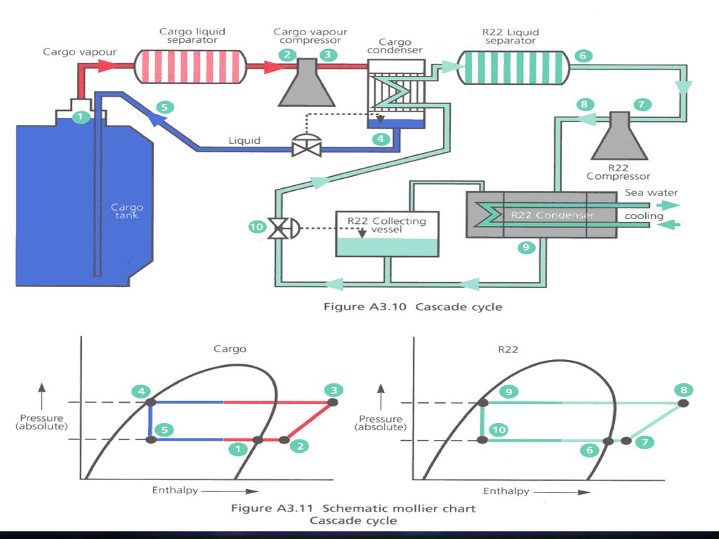
282283. Direct system – cascade
This system is virtually identical to thesingle-stage direct system, except that
the cargo condenser is cooled by liquid
refrigerant gas such as R22.
The system can be used for fully
refrigerated cargoes.
283
284. Direct system – cascade
Major advantages:the capacity of the system is not affected
by sea-water temperatures as much as
other systems.
The cycle is also more efficient, as the R22
temperature in the LPG condenser can be
below 0°C.
284
285.
285286. Compressors
Compressors are usually reciprocatingoil-free piston type, or screw-type
compressors
286
287. Reciprocating compressor
Often a two stagereciprocating
compressor is used
in the reliquefaction
plant
Click icon to view
287
288. Direct system: example
288289. Direct system: example
289290. Screw compressor
290291. Screw compressor
Dry oil-free :no physical contact between the screw rotors
leakage through the clearance
high speeds for good efficiency (12000 rpm)
4 and 6 lobes, 3 chambers
oil-flooded :
oil injection into the rotors
oil is lubricant and coolant
less gas leakage, lower speed (3000 rpm)
an oil separator on the discharge side removes oil from
the compressed gas
291
292. Indirect system
292293. Indirect system
Indirect cooling is used for cargoeswhich cannot be compressed for
chemical reasons
The cycle has to use a very cold
refrigerant in the condenser for
efficiency; the common refrigerants are
hydrogen, helium and propane
293
294. Reliquefaction plant operations precautions
1. Gas detection equipment should betested and activated before operation
begins
2. All Reliquefaction plant space vent
system should be activated at least 10
min before beginning
3. Compressors suction filters to be
checked and cleaned regularly
294
295. Reliquefaction plant operations precautions
4. Precautions for ice formation should beobserved
5. All pipelines and valves should be lined up
before starting
6. Cooling water supply should run and if
fitted coolant compressor started
7. Incondensible gases will affect the
Reliquefaction plant (ethane, methane or IG)
295
296. Reliquefaction plant precautions
Before starting the plant:Check that ventilation is up and running
Check and level of oil in carter
Check that compressor turns freely
Check that drains are closed and all valves
lined up
296
297. Venting boil-off to atmosphere
In case the gas burning system or thereliquefaction plant is out of order
Usually prohibited within harbour limits
297
298. Ship/shore interface
In this last part, we will discuss the shipto shore interface
The area where the activities of
shipboard and shore personnel overlap
during cargo handling operations
298
299. Ship/shore interface
Direct contact should be establishedbetween ship and shore as soon as
possible
Plans of mooring facilities and discharge
operations should be exchanged
299
300. Ship/shore interface
Before commencing any cargooperations a meeting should take place
between the responsible personnel from
ship and terminal
Following points to be discussed:
Names and roles of responsible personnel
Cargo and vessel equipment conform to
requirements
.../...
300
301. Ship/shore interface
.../...Terminal equipment conform and inspected
Condition of cargo and/or cargo tanks
Cargo quantities
Planning of the cargo ops re. temp., rates, startup,
sequences, pressures, use of vapour return, ballast
ops, ...
Previous three cargoes
Appropriate cargo hazard sheets available and
posted
.../...
301
302. Ship/shore interface
.../...Review of port and terminal regulations
Ship regulations and emergency
procedures
All other elevant info
Safety checklists should be completed
following guidelines
302