


 Промышленность
Похожие презентации:


Dialog+SW 9.xx Hydraulics. Technical Support International
1.
Dialog+ SW 9.xxHydraulics
Technical Support International
Enter
Service Training Documentation – no update service. This document may not be copied, partly or whole, or
made be accessible to third parties without our permission and remains the property of B. Braun Avitum AG
with all rights.
2.
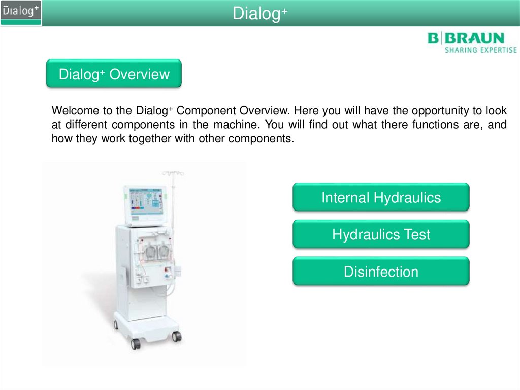
Dialog+Dialog+ Overview
Welcome to the Dialog+ Component Overview. Here you will have the opportunity to look
at different components in the machine. You will find out what there functions are, and
how they work together with other components.
Internal Hydraulics
Hydraulics Test
Disinfection
3.
StartDialog+
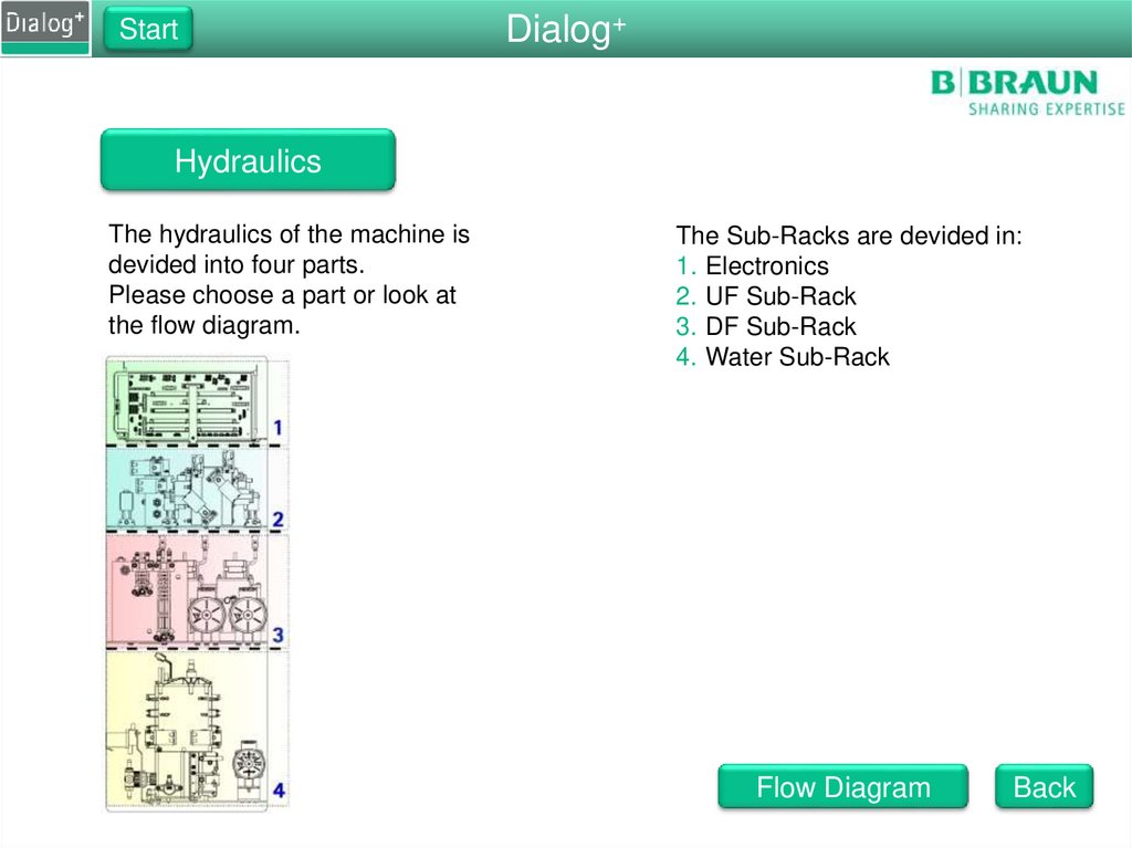
Hydraulics
The hydraulics of the machine is
devided into four parts.
Please choose a part or look at
the flow diagram.
The Sub-Racks are devided in:
1. Electronics
2. UF Sub-Rack
3. DF Sub-Rack
4. Water Sub-Rack
Flow Diagram
Back
4.
StartDialog+
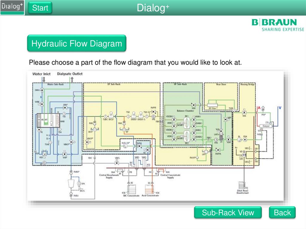
Hydraulic Flow Diagram
Please choose a part of the flow diagram that you would like to look at.
Sub-Rack View
Back
5.
StartWater Sub-Rack
Water Sub-Rack
Please choose one of the component groups of
the water sub-rack.
Functions of the Water Sub-Rack
Controls incoming water amount
Degasses the water
Heats the water
Contains bicarbonate valves
Degassing Circuit
Heating Circuit
Back
6.
StartWater Sub-Rack
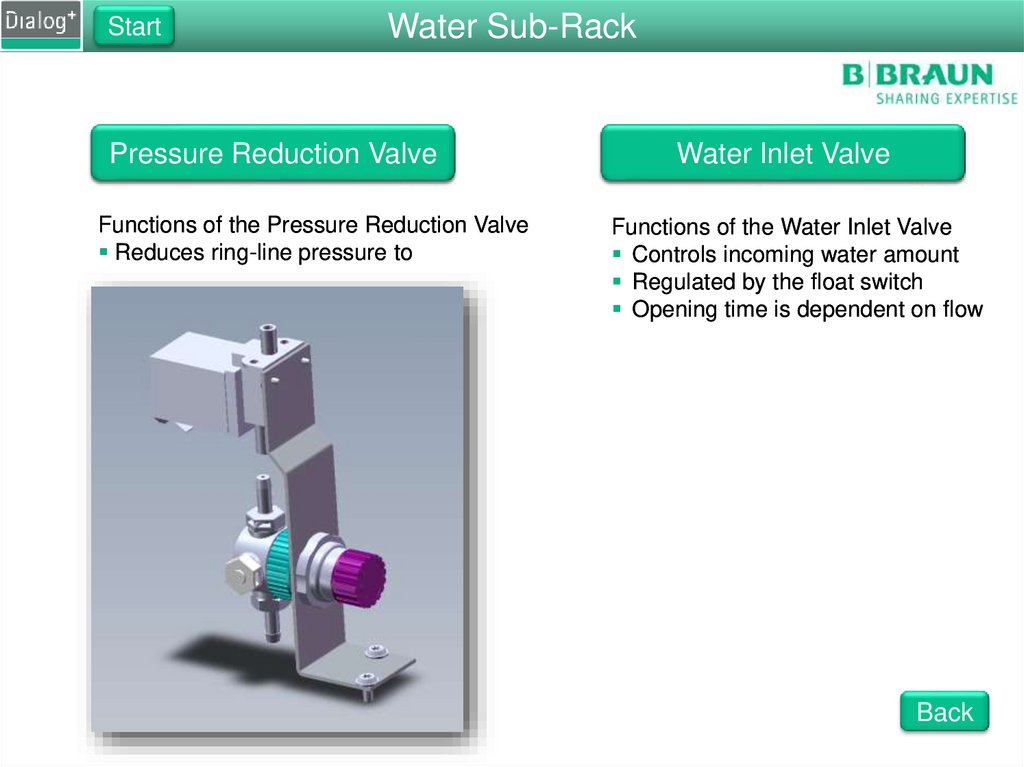
Pressure Reduction Valve
Functions of the Pressure Reduction Valve
Reduces ring-line pressure to 0.9 bar
Water Inlet Valve
Functions of the Water Inlet Valve
Controls incoming water amount
Regulated by the float switch
Opening time is dependent on flow
Back
7.
StartWater Sub-Rack
Water Block
Please choose one of the components on
the water block or the cover to look inside.
Functions of the Water Block
Mounting for all the valves
Contains the upline tank
Contains the degassing chamber
Contains the heating chamber
Back
8.
StartWater Sub-Rack
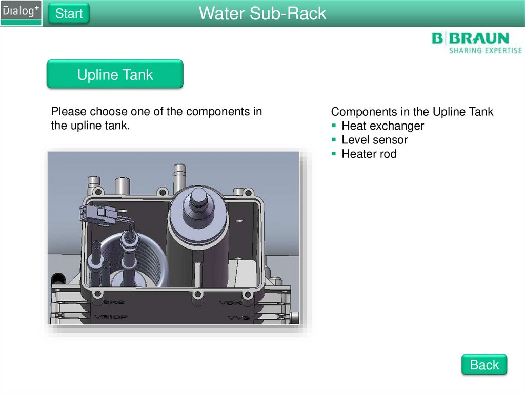
Upline Tank
Please choose one of the components in
the upline tank.
Components in the Upline Tank
Heat exchanger
Level sensor
Heater rod
Back
9.
StartWater Sub-Rack
Degassing Valve VEB
Functions of the Degassing Valve
Creates a restriction in the water flow
The restriction creates a negative
pressure
If the valve is open there is no
restiction in the flow
If the valve is closed there is a fixed
gap for the water to pass
The valve will always be open during
disinfections
Back
10.
StartWater Sub-Rack
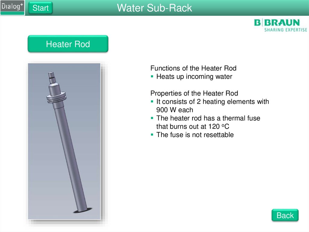
Heater Rod
Functions of the Heater Rod
Heats up incoming water
Properties of the Heater Rod
It consists of 2 heating elements with
900 W each
The heater rod has a thermal fuse
that burns out at 120 oC
The fuse is not resettable
Back
11.
StartWater Sub-Rack
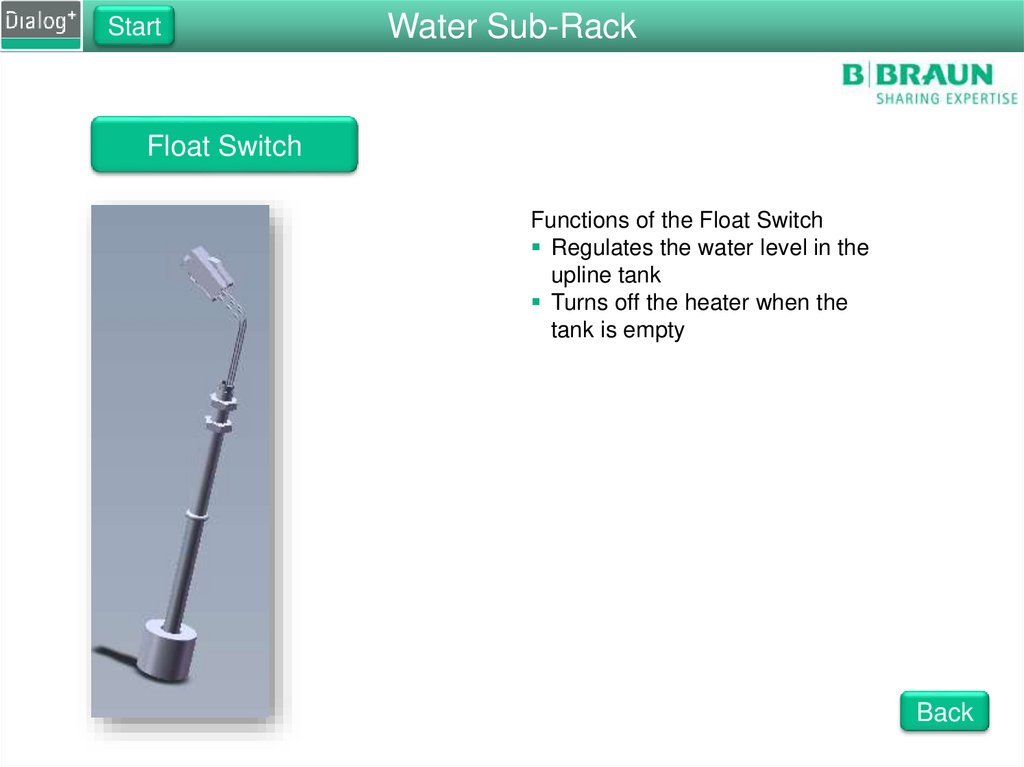
Float Switch
Functions of the Float Switch
Regulates the water level in the
upline tank
Turns off the heater when the
tank is empty
Back
12.
StartWater Sub-Rack
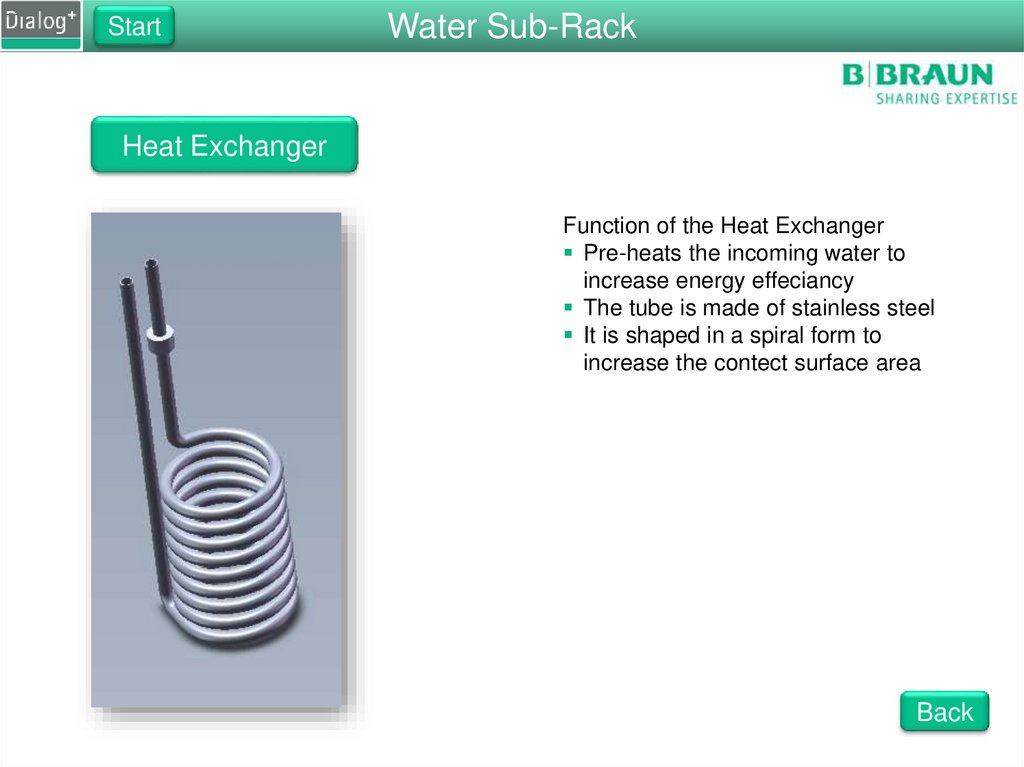
Heat Exchanger
Function of the Heat Exchanger
Pre-heats the incoming water to
increase energy effeciancy
The tube is made of stainless steel
It is shaped in a spiral form to
increase the contect surface area
Back
13.
StartWater Sub-Rack
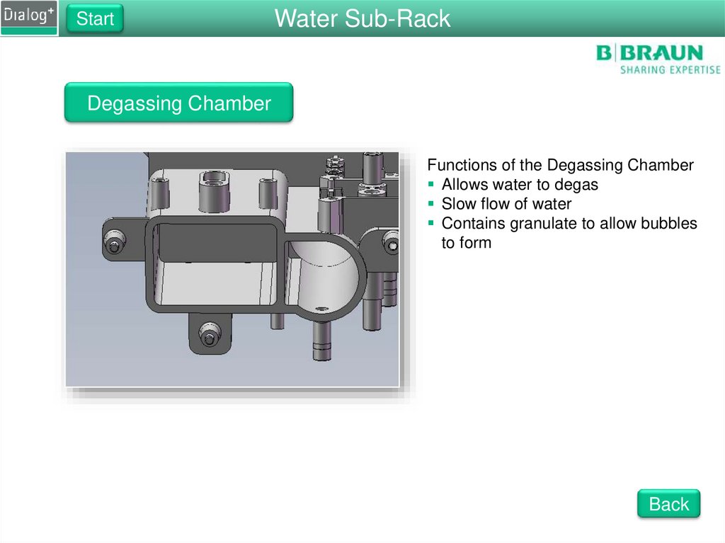
Degassing Chamber
Functions of the Degassing Chamber
Allows water to degas
Slow flow of water
Contains granulate to allow bubbles
to form
Back
14.
StartWater Sub-Rack
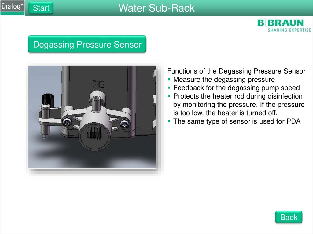
Degassing Pressure Sensor
Functions of the Degassing Pressure Sensor
Measure the degassing pressure
Feedback for the degassing pump speed
Protects the heater rod during disinfection
by monitoring the pressure. If the pressure
is too low, the heater is turned off.
The same type of sensor is used for PDA
Back
15.
StartWater Sub-Rack
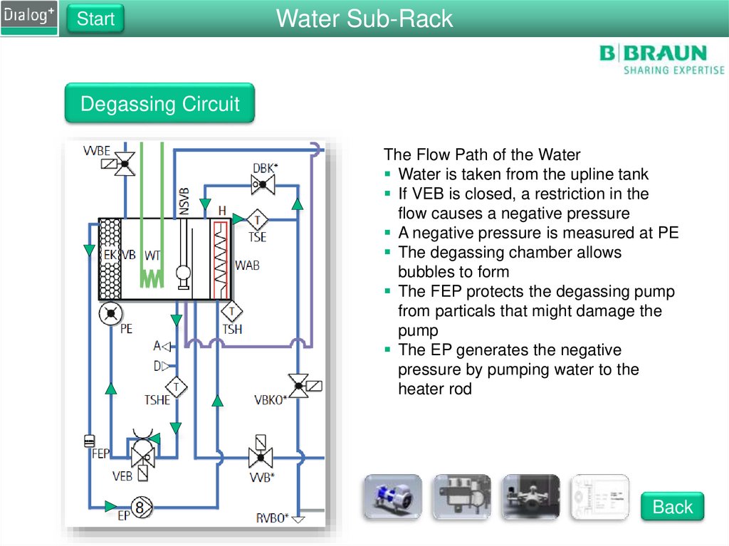
Degassing Circuit
The Flow Path of the Water
Water is taken from the upline tank
If VEB is closed, a restriction in the
flow causes a negative pressure
A negative pressure is measured at PE
The degassing chamber allows
bubbles to form
The FEP protects the degassing pump
from particals that might damage the
pump
The EP generates the negative
pressure by pumping water to the
heater rod
Back
16.
StartWater Sub-Rack
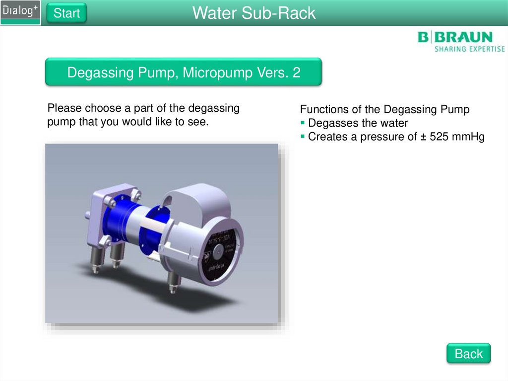
Degassing Pump, Micropump Vers. 2
Please choose a part of the degassing
pump that you would like to see.
Functions of the Degassing Pump
Degasses the water
Creates a pressure of ± 525 mmHg
Back
17.
StartWater Sub-Rack
Degassing Pump
Functions of the Degassing Pump
Creates a negative degassing
pressure
Pumps fluid with two interlocked
gears
The gears are driven by a magnet
The pump can only pump water
If the pump speed is too low the
heater is turned off
Degassing pressure should be at
least ± 525 mmHg
Back
18.
StartWater Sub-Rack
Degassing Motor
Functions of the Degassing Motor
Drives the degassing pump
Onboard driving circuits
Is regulated by the degassing pressure
Back
19.
StartWater Sub-Rack
Degassing Motor Cover
Functions of the Degassing Motor Cover
Protects the moving parts of the motor
Protects the electronics of the motor
Back
20.
StartWater Sub-Rack
Degassing Adaptor Block
Function of the Adaptor Block
Mounting of the degassing pump
O-rings to seal the connection with
the motor
Four clips to hold the motor
Back
21.
StartWater Sub-Rack
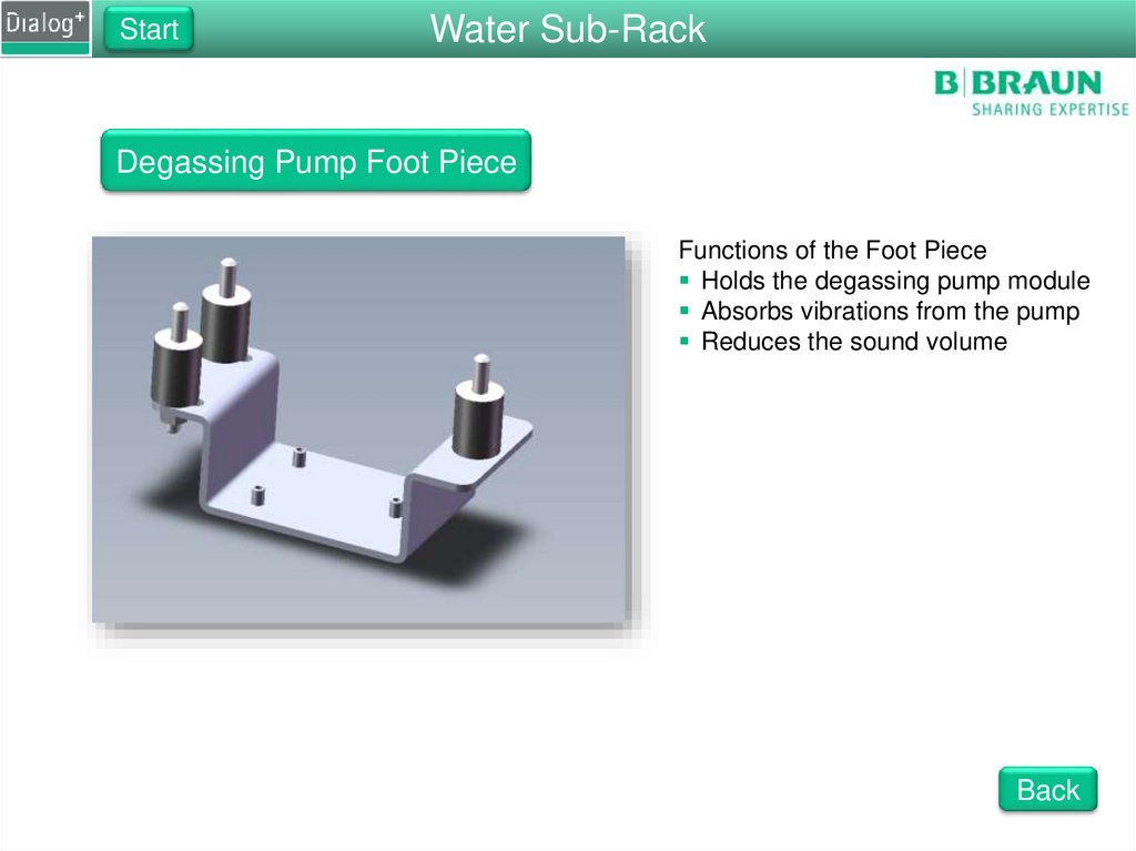
Degassing Pump Foot Piece
Functions of the Foot Piece
Holds the degassing pump module
Absorbs vibrations from the pump
Reduces the sound volume
Back
22.
Water Sub-RackStart
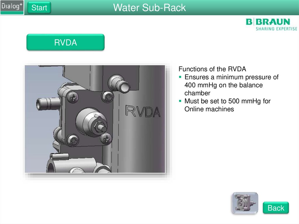
RVDA
Functions of the RVDA
Ensures a minimum pressure of
400 mmHg on the balance
chamber
Must be set to 500 mmHg for
Online machines
Back
23.
Water Sub-RackStart
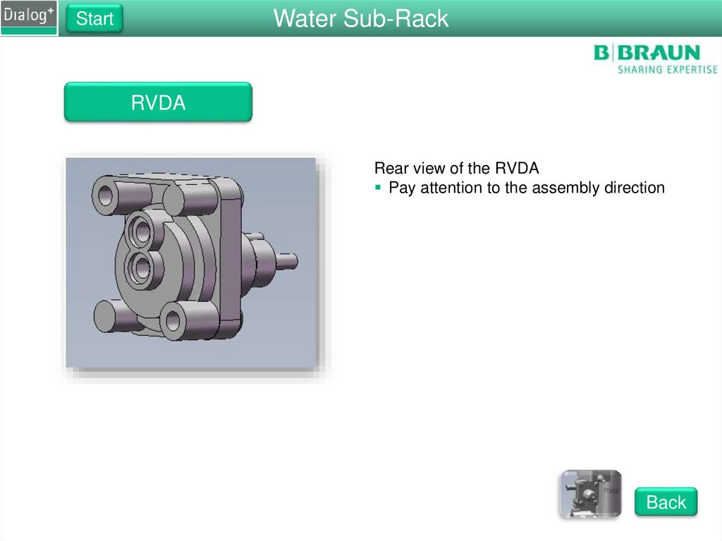
RVDA
Rear view of the RVDA
Pay attention to the assembly direction
Back
24.
StartUF Sub-Rack
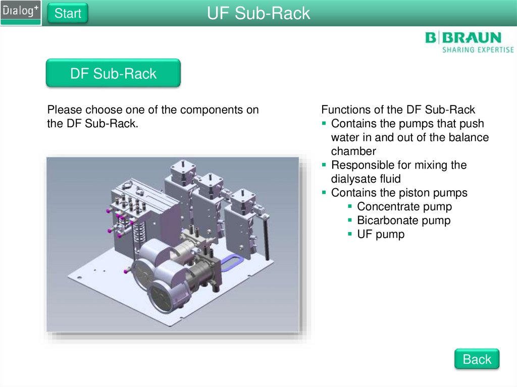
DF Sub-Rack
Please choose one of the components on
the DF Sub-Rack.
Functions of the DF Sub-Rack
Contains the pumps that push
water in and out of the balance
chamber
Responsible for mixing the
dialysate fluid
Contains the piston pumps
Concentrate pump
Bicarbonate pump
UF pump
Back
25.
StartDF Sub-Rack
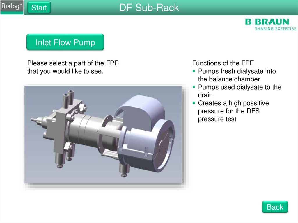
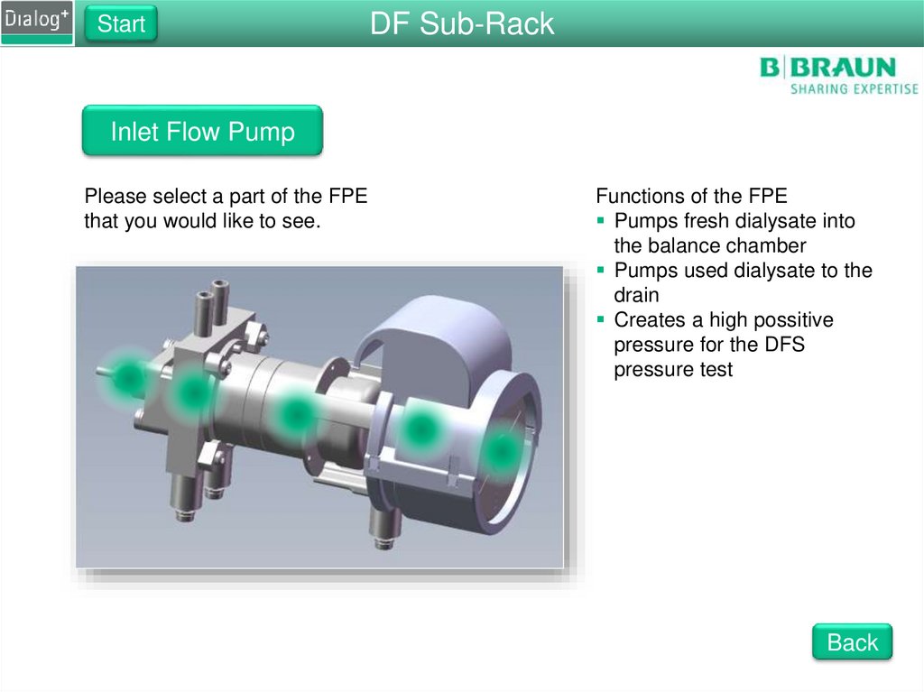
Inlet Flow Pump
Please select a part of the FPE
that you would like to see.
Functions of the FPE
Pumps fresh dialysate into
the balance chamber
Pumps used dialysate to the
drain
Creates a high possitive
pressure for the DFS
pressure test
Back
26.
StartDF Sub-Rack
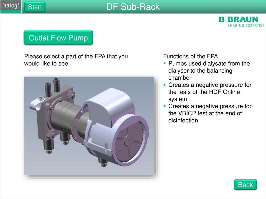
Outlet Flow Pump
Please select a part of the FPA that you
would like to see.
Functions of the FPA
Pumps used dialysate from the
dialyser to the balancing
chamber
Creates a negative pressure for
the tests of the HDF Online
system
Creates a negative pressure for
the VBICP test at the end of
disinfection
Back
27.
UF Sub-RackStart
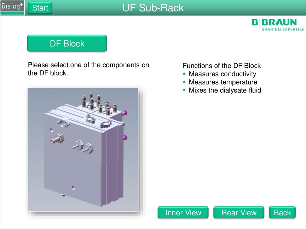
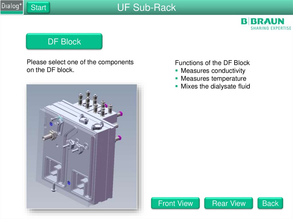
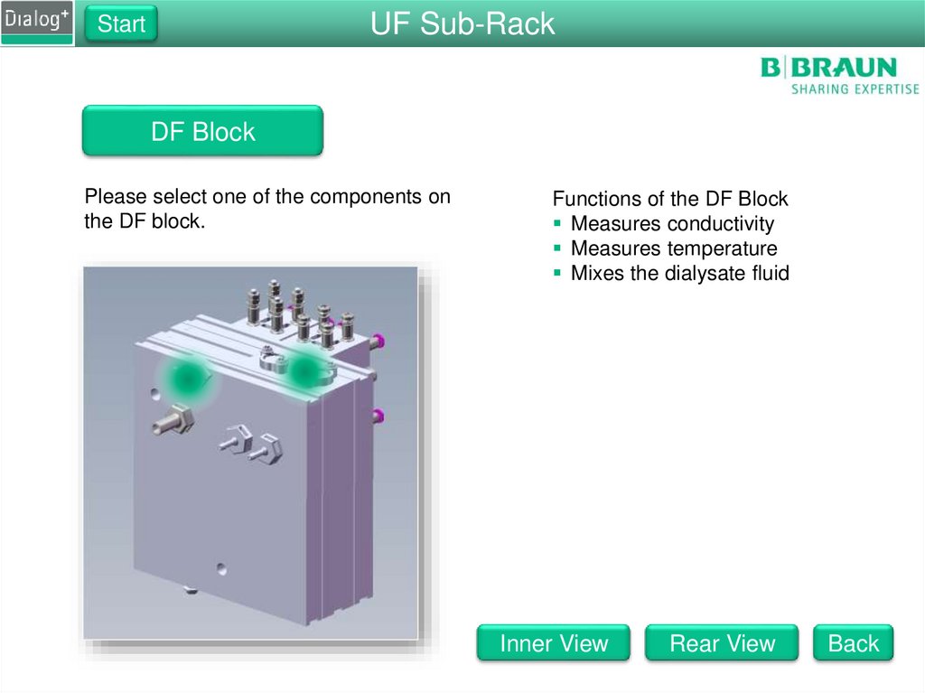
DF Block
Please select one of the components on
the DF block.
Functions of the DF Block
Measures conductivity
Measures temperature
Mixes the dialysate fluid
Inner View
Rear View
Back
28.
UF Sub-RackStart
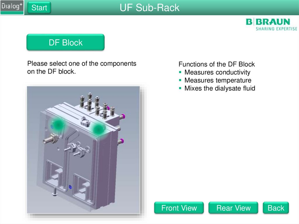
DF Block
Please select one of the components
on the DF block.
Functions of the DF Block
Measures conductivity
Measures temperature
Mixes the dialysate fluid
Front View
Rear View
Back
29.
UF Sub-RackStart
DF Block
Please select one of the components
on the DF block.
Functions of the DF Block
Measures conductivity
Measures temperature
Mixes the dialysate fluid
Inner View
Front View
Back
30.
StartDF Sub-Rack
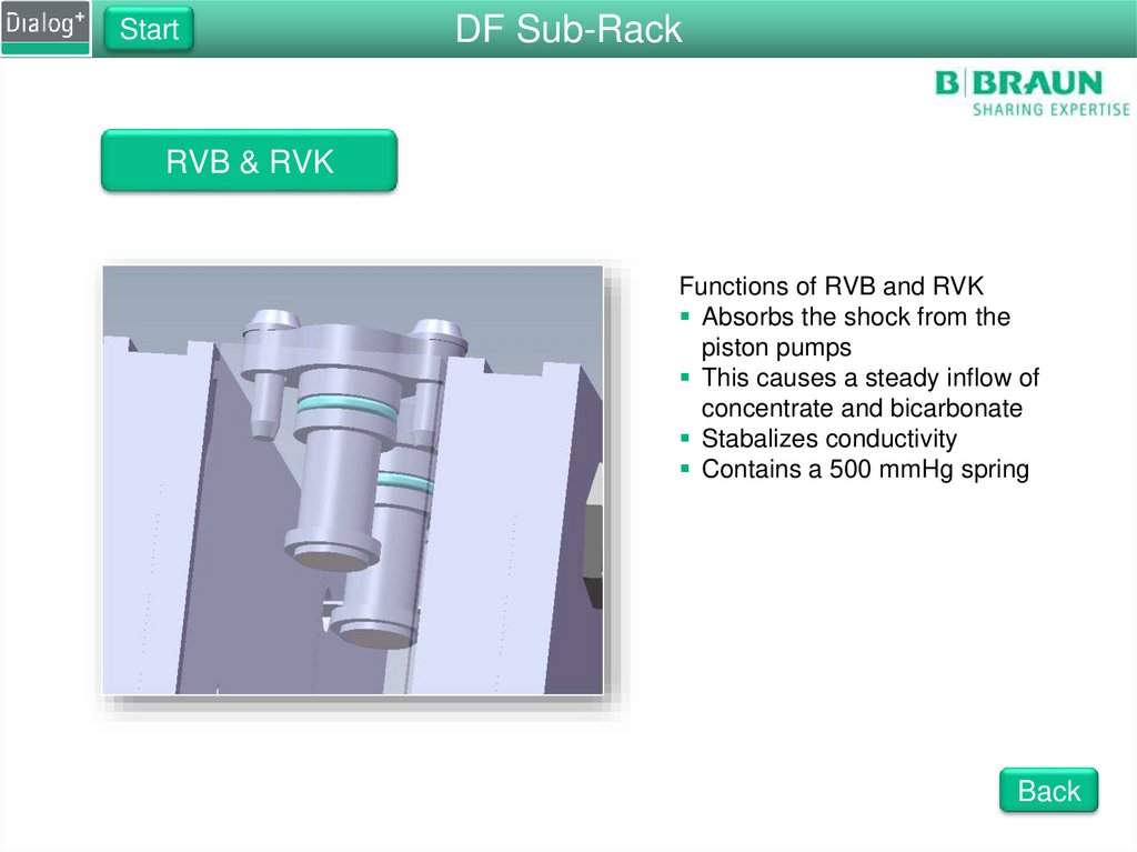
RVB & RVK
Functions of RVB and RVK
Absorbs the shock from the
piston pumps
This causes a steady inflow of
concentrate and bicarbonate
Stabalizes conductivity
Contains a 500 mmHg spring
Back
31.
StartDF Sub-Rack
Concentrate and Bicarbonate Pumps
Pump Functions
Pumps concentrate and
bicarbonate into the DF block
Normal speed is ± 60 rpm
Consists of
Pump body
Bell
Hall sensor
Motor
The speed is regulated by the
conductivity cells
Back
32.
StartDF Sub-Rack
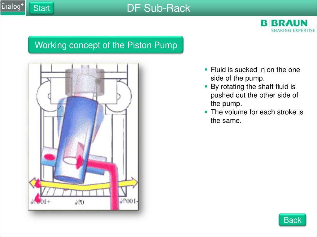
Working concept of the Piston Pump
Fluid is sucked in on the one
side of the pump.
By rotating the shaft fluid is
pushed out the other side of
the pump.
The volume for each stroke is
the same.
Back
33.
DF Sub-RackStart
RVFPE
Functions of the RVFPE
Prevents an over pressure
Set to 1.3 bar
Prevents tubes from
popping off
Back
34.
StartDF Sub-Rack
Concentrate and Bicarbonate Pumps
UF Pump Functions
Pumps the UF volume to drain
Remove fluid from the patient
Calibrated accurately
Tolerence of 1 %
Consists of
Pump body
Bell
Hall sensor
Motor
Back
35.
DF Sub-RackStart
Temperature Sensors
Functions of TSD_S
Measures the temperature for ENDLF_S
Is used to compensate the conductivity measurement
Should be equal to TSD
Functions of TSD
Measures the temperature for ENDLF
Is used to compensate the conductivity measurement
Should be equal to TSD_S
Functions of TSBIC
Measures the temperature for TSBIC
Is used to compensate the conductivity measurement
Should be slightly colder than TSD
Terbulance Spacer
Back
36.
StartDF Sub-Rack
Terbulance Spacer
Functions of the Terbulance Spacer
Creates terbulance on the
temperature sensor
Removes dead spaces from the
sensor
Back
37.
DF Sub-RackStart
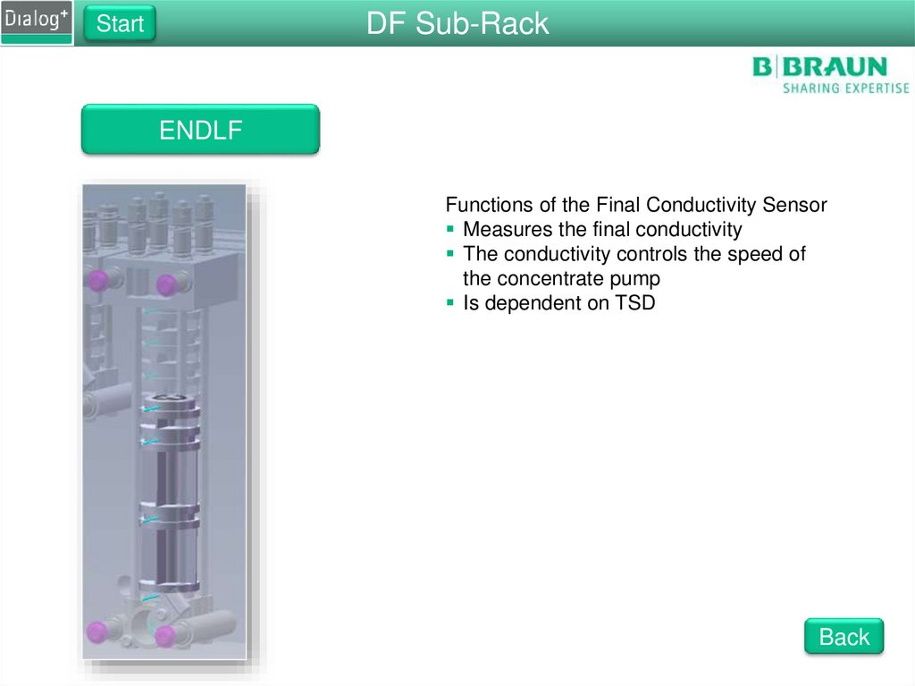
ENDLF
Functions of the Final Conductivity Sensor
Measures the final conductivity
The conductivity controls the speed of
the concentrate pump
Is dependent on TSD
Back
38.
StartDF Sub-Rack
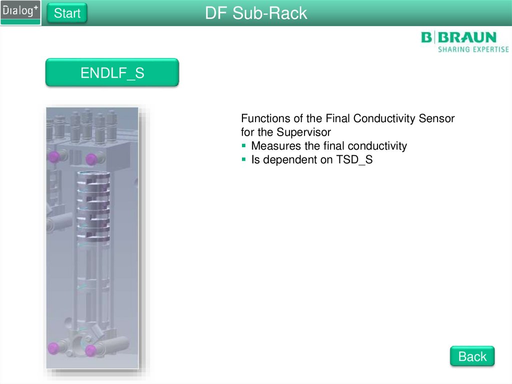
ENDLF_S
Functions of the Final Conductivity Sensor
for the Supervisor
Measures the final conductivity
Is dependent on TSD_S
Back
39.
DF Sub-RackStart
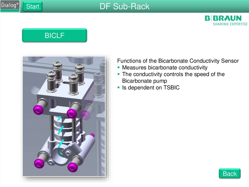
BICLF
Functions of the Bicarbonate Conductivity Sensor
Measures bicarbonate conductivity
The conductivity controls the speed of the
Bicarbonate pump
Is dependent on TSBIC
Back
40.
StartDF Sub-Rack
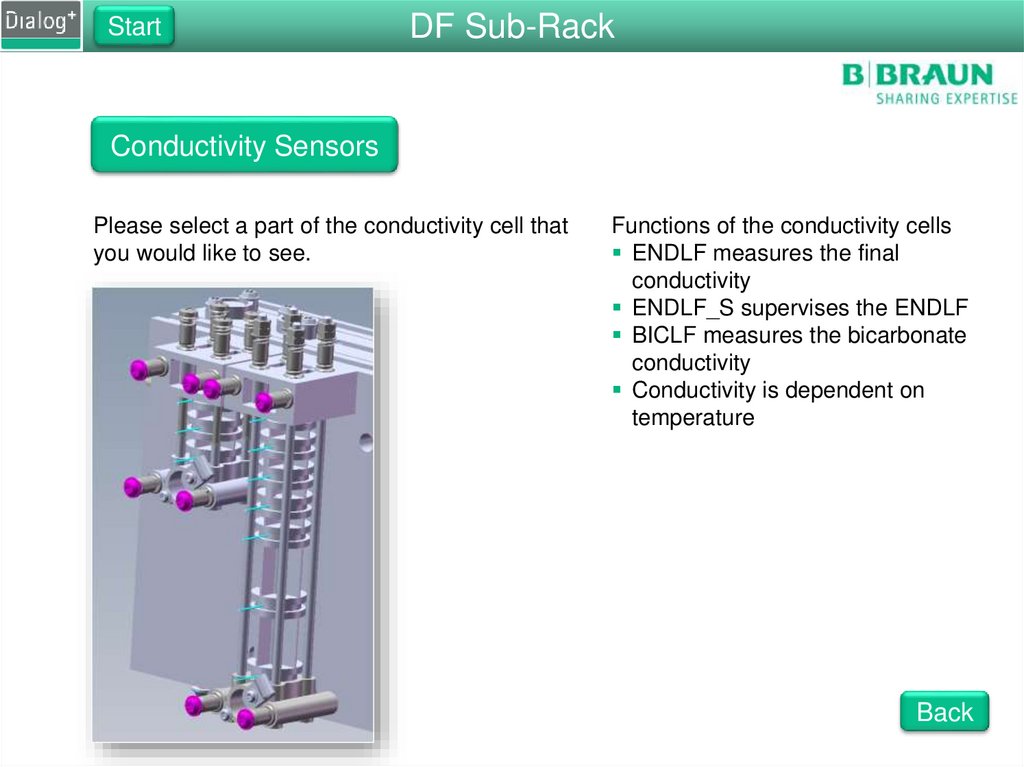
Conductivity Sensors
Please select a part of the conductivity cell that
you would like to see.
Functions of the conductivity cells
ENDLF measures the final
conductivity
ENDLF_S supervises the ENDLF
BICLF measures the bicarbonate
conductivity
Conductivity is dependent on
temperature
Back
41.
StartRinsing Bridge
O-Rings of the Disinfection Valve
Function of the O-Rings
Lower O-ring: seals of the disinfection
port from the dialysate lines
Upper O-ring: prevents the machine
from sucking air when disinfection is
taken into the machine
Back
42.
StartRinsing Bridge
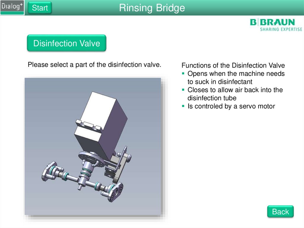
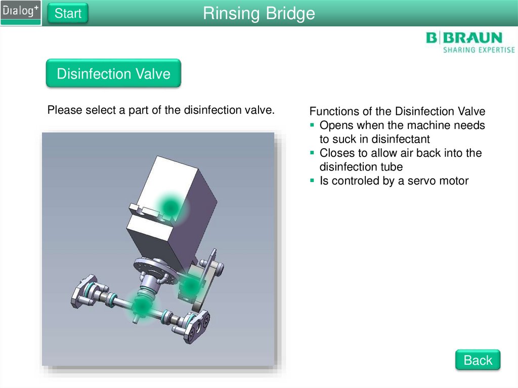
Disinfection Valve
Please select a part of the disinfection valve.
Functions of the Disinfection Valve
Opens when the machine needs
to suck in disinfectant
Closes to allow air back into the
disinfection tube
Is controled by a servo motor
Back
43.
StartSub-Rack
FPA Adaptor Block
Functions of the FPA Adaptor Block
Mounts the FPA
Absorbs vibrations for noise reduction
Back
44.
StartRinsing Bridge
Light Barrior
Function of the Light Barrior
Senses the position of the
disinfection valve
Back
45.
StartRinsing Bridge
Pressure Sensor Dialysate
Functions of PDA
Measure the dialysate pressure
This is used to calculate TMP
Used as testing device during
the DFS Pressure Test
Large working range
The same type of sensor as PE
Back
46.
StartRinsing Bridge
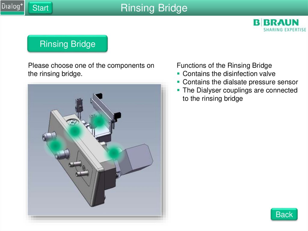
Rinsing Bridge
Please choose one of the components on
the rinsing bridge.
Functions of the Rinsing Bridge
Contains the disinfection valve
Contains the dialsate pressure sensor
The Dialyser couplings are connected
to the rinsing bridge
Back
47.
StartRinsing Bridge
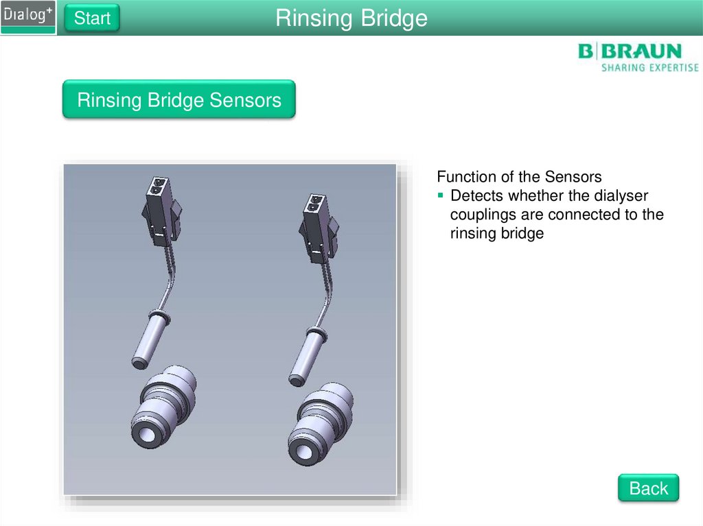
Rinsing Bridge Sensors
Function of the Sensors
Detects whether the dialyser
couplings are connected to the
rinsing bridge
Back
48.
StartRinsing Bridge
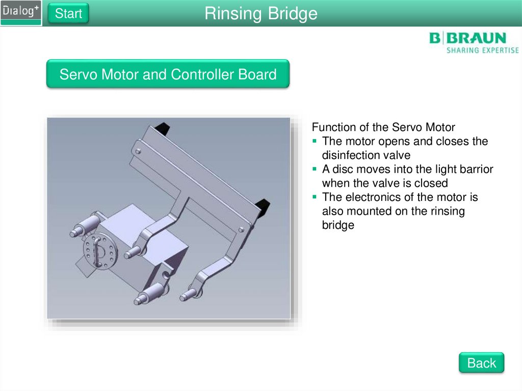
Servo Motor and Controller Board
Function of the Servo Motor
The motor opens and closes the
disinfection valve
A disc moves into the light barrior
when the valve is closed
The electronics of the motor is
also mounted on the rinsing
bridge
Back
49.
StartDF Sub-Rack
FPE Motor Cover
Functions of the FPE Motor Cover
Protects the moving parts of the motor
Protects the electronics of the motor
Back
50.
StartDF Sub-Rack
FPE Motor
Functions of the FPE Motor
Drives the degassing pump
Onboard driving circuits
Is regulated by the degassing pressure
Back
51.
StartDF Sub-Rack
FPA Motor
Functions of the FPA Motor
Drives the degassing pump
Onboard driving circuits
Is regulated by the degassing pressure
Back
52.
StartDF Sub-Rack
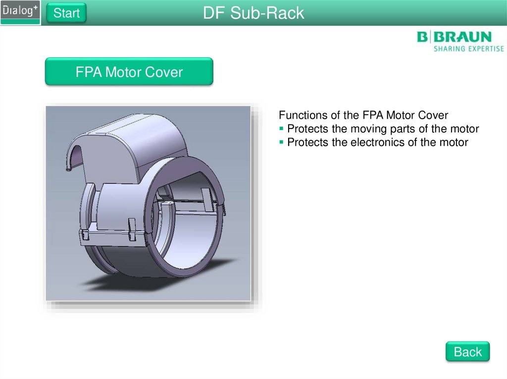
FPA Motor Cover
Functions of the FPA Motor Cover
Protects the moving parts of the motor
Protects the electronics of the motor
Back
53.
StartDialog+
Hydraulic Flow Diagram
Please choose a part of the flow diagram that you would like to look at.
Touch one of the green areas.
Sub-Rack View
Back
54.
StartDF Sub-Rack
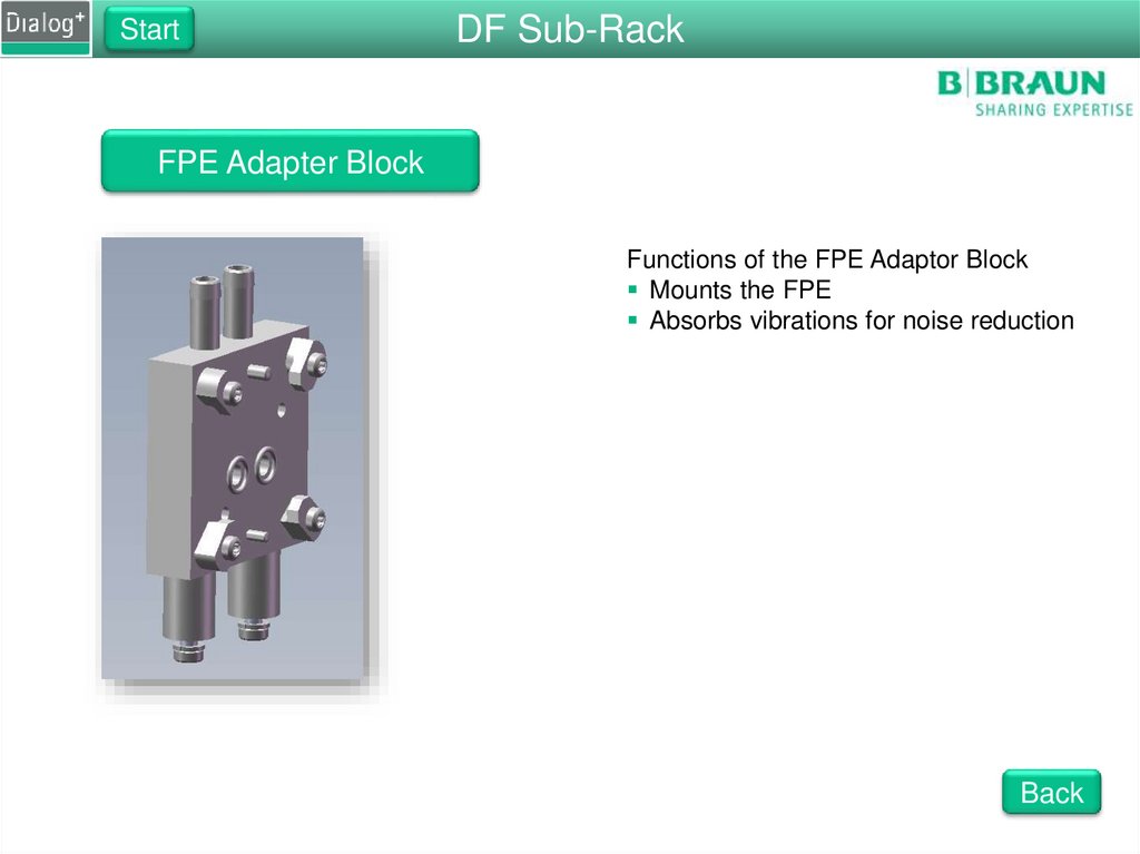
FPE Adapter Block
Functions of the FPE Adaptor Block
Mounts the FPE
Absorbs vibrations for noise reduction
Back
55.
StartDF Sub-Rack
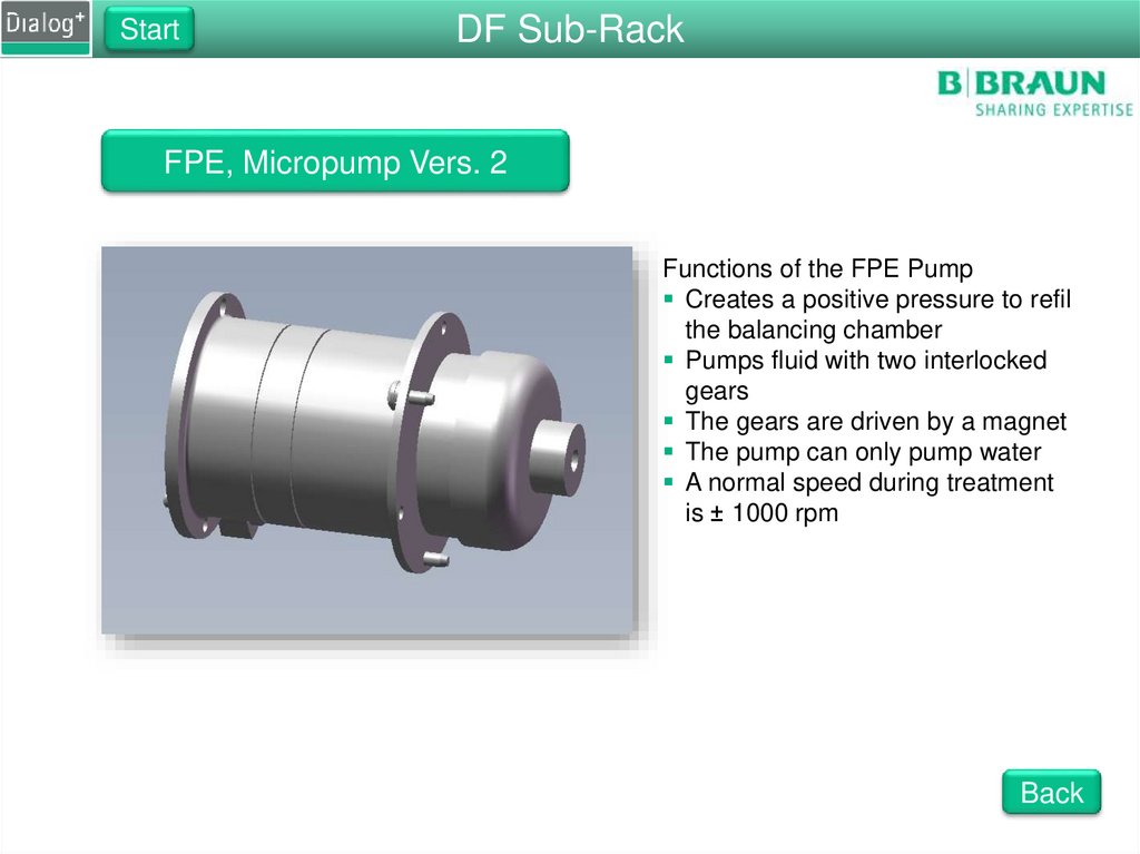
FPE, Micropump Vers. 2
Functions of the FPE Pump
Creates a positive pressure to refil
the balancing chamber
Pumps fluid with two interlocked
gears
The gears are driven by a magnet
The pump can only pump water
A normal speed during treatment
is ± 1000 rpm
Back
56.
StartDF Sub-Rack
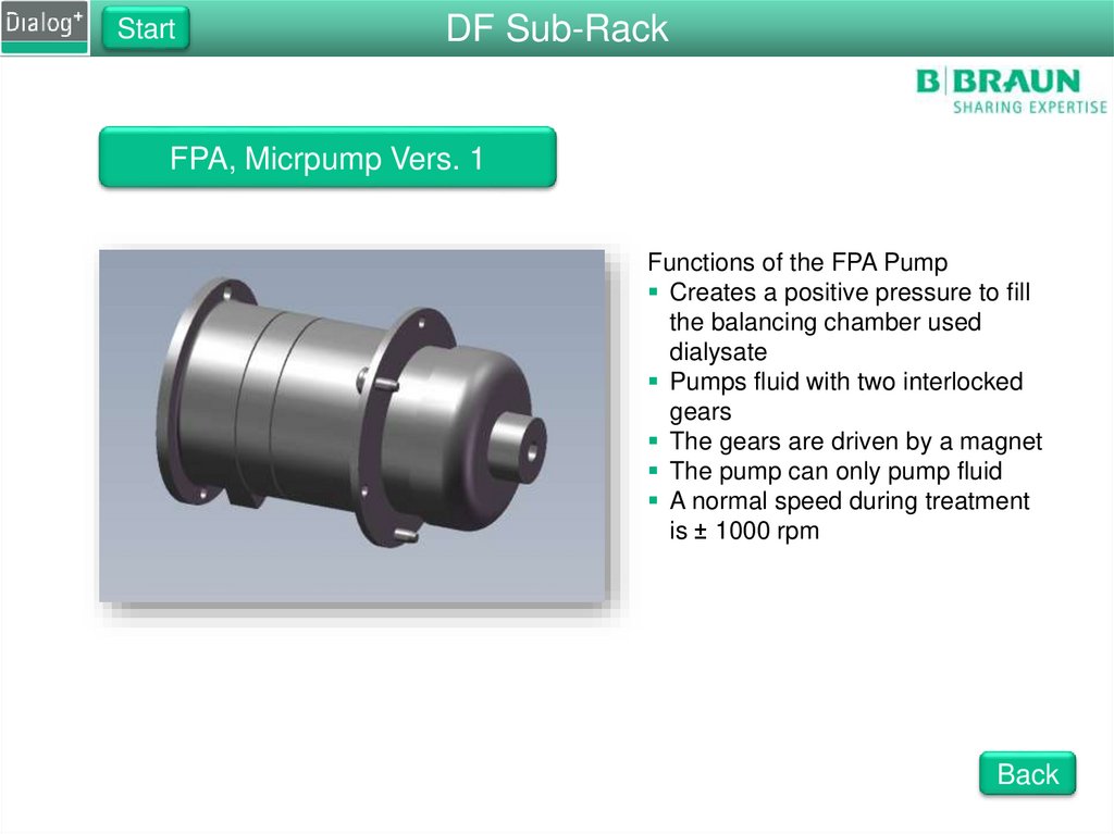
FPA, Micrpump Vers. 1
Functions of the FPA Pump
Creates a positive pressure to fill
the balancing chamber used
dialysate
Pumps fluid with two interlocked
gears
The gears are driven by a magnet
The pump can only pump fluid
A normal speed during treatment
is ± 1000 rpm
Back
57.
StartUF Sub-Rack
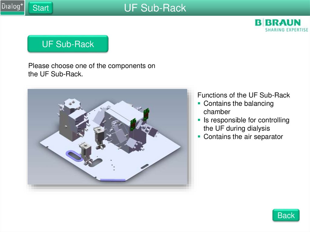
UF Sub-Rack
Please choose one of the components on
the UF Sub-Rack.
Functions of the UF Sub-Rack
Contains the balancing
chamber
Is responsible for controlling
the UF during dialysis
Contains the air separator
Back
58.
StartUF Sub-Rack
Air Separator
Functions of the Air Separator
Prevents air from entering the
balancing chamber
Contains VLA and VBP
Contains DDE and RVFPA
Back
59.
StartUF Sub-Rack
Air Separator
Functions of the Air Separator
Prevents air from entering the
balancing chamber
Contains VLA and VBP
Contains DDE and RVFPA
Back
60.
StartUF Sub-Rack
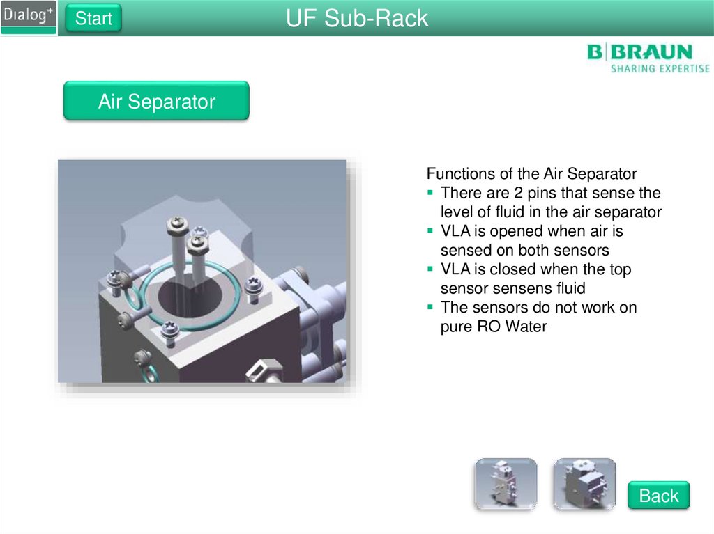
Air Separator
Functions of the Air Separator
There are 2 pins that sense the
level of fluid in the air separator
VLA is opened when air is
sensed on both sensors
VLA is closed when the top
sensor sensens fluid
The sensors do not work on
pure RO Water
Back
61.
StartUF Sub-Rack
Balance Chamber
Functions of the Balance Chamber
Consists of 2 chambers, with 8
valves
Induction coils measure the
membrane positions
Back
62.
StartUF Sub-Rack
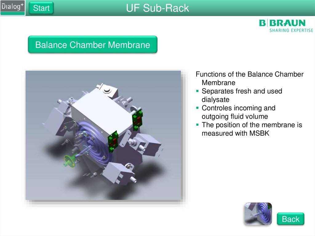
Balance Chamber Membrane
Functions of the Balance Chamber
Membrane
Separates fresh and used
dialysate
Controles incoming and
outgoing fluid volume
The position of the membrane is
measured with MSBK
Back
63.
StartUF Sub-Rack
Membrane Position Sensor
Functions of the membrane
position sensor
Measures the position of the
membrane
Uses induction to sense the
position of a metal pin inside of
the membrane
The pin moves in and out of the
coil in the sensor
The result is shown in μS
Back
64.
StartWater Sub-Rack
Water Sub-Rack
Please choose one of the component groups of
the water sub-rack.
Functions of the Water Sub-Rack
Controls incoming water amount
Degasses the water
Heats the water
Contains bicarbonate valves
Degassing Circuit
Heating Circuit
Back
65.
StartWater Sub-Rack
Water Block
Please choose one of the components on
the water block or the cover to look inside.
Functions of the Water Block
Mounting for all the valves
Contains the upline tank
Contains the degassing chamber
Contains the heating chamber
Back
66.
StartWater Sub-Rack
Upline Tank
Please choose one of the components in
the upline tank.
Components in the Upline Tank
Heat exchanger
Level sensor
Heater rod
Back
67.
StartWater Sub-Rack
Degassing Pump, Micropump Vers. 2
Please choose a part of the degassing
pump that you would like to see.
Functions of the Degassing Pump
Degasses the water
Creates a pressure of ± 525 mmHg
Back
68.
StartUF Sub-Rack
DF Sub-Rack
Please choose one of the components on
the DF Sub-Rack.
Functions of the DF Sub-Rack
Contains the pumps that push
water in and out of the balance
chamber
Responsible for mixing the
dialysate fluid
Contains the piston pumps
Concentrate pump
Bicarbonate pump
UF pump
Back
69.
StartDF Sub-Rack
Inlet Flow Pump
Please select a part of the FPE
that you would like to see.
Functions of the FPE
Pumps fresh dialysate into
the balance chamber
Pumps used dialysate to the
drain
Creates a high possitive
pressure for the DFS
pressure test
Back
70.
StartDF Sub-Rack
Outlet Flow Pump
Please select a part of the FPA that you
would like to see.
Functions of the FPA
Pumps used dialysate from the
dialyser to the balancing
chamber
Creates a negative pressure for
the tests of the HDF Online
system
Creates a negative pressure for
the VBICP test at the end of
disinfection
Back
71.
UF Sub-RackStart
DF Block
Please select one of the components on
the DF block.
Functions of the DF Block
Measures conductivity
Measures temperature
Mixes the dialysate fluid
Inner View
Rear View
Back
72.
UF Sub-RackStart
DF Block
Please select one of the components
on the DF block.
Functions of the DF Block
Measures conductivity
Measures temperature
Mixes the dialysate fluid
Front View
Rear View
Back
73.
UF Sub-RackStart
DF Block
Please select one of the components
on the DF block.
Functions of the DF Block
Measures conductivity
Measures temperature
Mixes the dialysate fluid
Inner View
Front View
Back
74.
StartDF Sub-Rack
Conductivity Sensors
Please select a part of the conductivity cell that
you would like to see.
Functions of the conductivity cells
ENDLF measures the final
conductivity
ENDLF_S supervises the ENDLF
BICLF measures the bicarbonate
conductivity
Conductivity is dependent on
temperature
Back
75.
StartRinsing Bridge
Disinfection Valve
Please select a part of the disinfection valve.
Functions of the Disinfection Valve
Opens when the machine needs
to suck in disinfectant
Closes to allow air back into the
disinfection tube
Is controled by a servo motor
Back
76.
StartRinsing Bridge
Rinsing Bridge
Please choose one of the components on
the rinsing bridge.
Functions of the Rinsing Bridge
Contains the disinfection valve
Contains the dialsate pressure sensor
The Dialyser couplings are connected
to the rinsing bridge
Back
77.
StartUF Sub-Rack
UF Sub-Rack
Please choose one of the components on
the UF Sub-Rack.
Functions of the UF Sub-Rack
Contains the balancing
chamber
Is responsible for controlling
the UF during dialysis
Contains the air separator
Back
78.
StartWater Sub-Rack
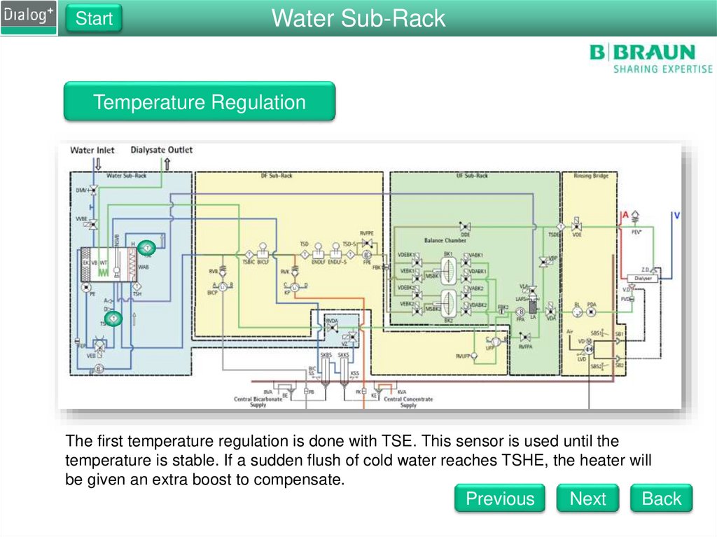
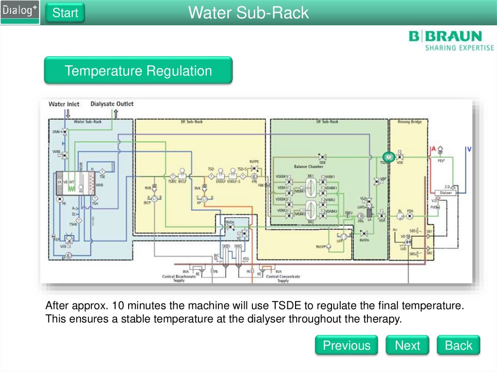
Temperature Regulation
The temperature regulation is done by the following components
TSE
TSHE
TSD
TSDE
Next
Back
79.
StartWater Sub-Rack
Temperature Regulation
The first temperature regulation is done with TSE. This sensor is used until the
temperature is stable. If a sudden flush of cold water reaches TSHE, the heater will
be given an extra boost to compensate.
Previous
Next
Back
80.
StartWater Sub-Rack
Temperature Regulation
Once the temperature is stable at TSE, the controller starts to regulate
the temperature with TSD.
Previous
Next
Back
81.
StartWater Sub-Rack
Temperature Regulation
After approx. 10 minutes the machine will use TSDE to regulate the final temperature.
This ensures a stable temperature at the dialyser throughout the therapy.
Previous
Next
Back
82.
StartWater Sub-Rack
Temperature Regulation
If the machine is switched to bypass, TSD will take over regulation of the temperature,
because there is no flow through TSDE. Regulation by TSDE is restored once the
temperature is stable again at TSD.
Previous
Next
Back
83.
StartWater Sub-Rack
Temperature Regulation
At all times during the therapy TSD-S is active to ensure patient safety. The maschine
will switch to bypass if the temperature exeeds 41°C at any time.
Previous
Back
84.
Dialog+Dialog+ Hydraulic Test
Welcome to the Dialog+ Component Overview. Here you will have the opportunity to look
at different components in Question
the machine.
1 You will find out what there functions are, and
how they work together with other components.
What compenent is not part of the water sub-rack?
A
The Disinfection Valve
B
The Degassing Valve
C
The Degassing Temperature Sensor
D
The Water Inlet Valve
Next
85.
Dialog+Dialog+ Hydraulic Test
Question 2
How many temperature sensors are in the machine?
A
4
B
5
C
6
D
7
Next
86.
Dialog+Dialog+ Hydraulic Test
Question 3
What is the status of the degassing valve during disinfection?
A
Closed
B
Open
C
Switches between open and closed
D
Only open for short times
Next
87.
Dialog+Dialog+ Hydraulic Test
Question 4
Which pump is responsable for pumping fresh dialysate fluid
into the balance chamber?
A
Flow Pump Inlet
B
Flow Pump Outlet
C
Flow Pump Inlet and Flow Pump Outlet
D
Degassing Pump
Next
88.
Dialog+Dialog+ Hydraulic Test
Question 5
What is the pressure of RVDA set to on a standard and
Online machine?
A
Standard: 400mmHg, Online: 400mmHg
B
Standard: 500mmHg, Online: 400mmHg
C
Standard: 400mmHg, Online: 500mmHg
D
Standard: 500mmHg, Online: 500mmHg
Next
89.
Dialog+Dialog+ Hydraulic Test
Question 6
Wat is the approx. speed for EP, FPE, FPA during therapy?
A
EP: 1500 rpm, FPE: 1800 rpm, FPA:1800 rpm
B
EP: 2000 rpm, FPE: 1000 rpm, FPA: 2000 rpm
C
EP: 2000 rpm, FPE: 1000 rpm, FPA: 1200rpm
D
EP: 2000 rpm, FPE: 1000 rpm, FPA: 1000rpm
Next
90.
Dialog+Dialog+ Hydraulic Test
Test Completed
Press the Show Results button to find out how many
questions were answered correctly.
Restart Test
Back
91.
Dialog+Chemical Thermal Disinfections
Negative
All
Upline
Air
Heater
pumps
Separator
Pressure
Tank
Rod
are
Emptied
running
Off
Built
FilledUp
Disinfectant Sucked Up
3 min
Disinfection
rinsing and
Valve
heating
Opened
to 45°C
-200mmHg
Next
92.
Dialog+Chemical Thermal Disinfections
All pumps are running
Minimum disinfection time, above minimum Temp
Next
93.
Dialog+Chemical Thermal Disinfections
VBICP
VBICP Test
Test phase
phase 12
Negative
PressurePressure
release with
withVVB
VVBand
andVBICP
VBICPopened
closed
Next
94.
Dialog+Chemical Thermal Disinfection
Rinsing out of disinfectant
Back
95.
StartWater Sub-Rack
Balance Chamber Concept
After approx. 10 minutes the machine will use TSDE to regulate the final temperature.
This ensures a stable temperature at the dialyser throughout the therapy.
Previous
Next
Back