


Похожие презентации:


Design and Optimization of Bolted and Pinned Bracket Joints (1)
1.
Design and OptimizationBolted and Pinned
Bracket Joints
Focus:
Shear stress • Bearing stress • Failure modes • Safety factor
Optimization
2.
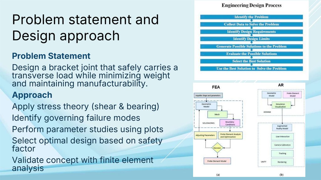
Problem statement andDesign approach
Problem Statement
Design a bracket joint that safely carries a
transverse load while minimizing weight
and maintaining manufacturability.
Approach
Apply stress theory (shear & bearing)
Identify governing failure modes
Perform parameter studies using plots
Select optimal design based on safety
factor
Validate concept with finite element
analysis
3.
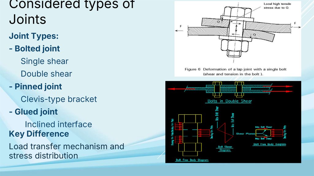
Considered types ofJoints
Joint Types:
- Bolted joint
Single shear
Double shear
- Pinned joint
Clevis-type bracket
- Glued joint
Inclined interface
Key Difference
Load transfer mechanism and
stress distribution
4.
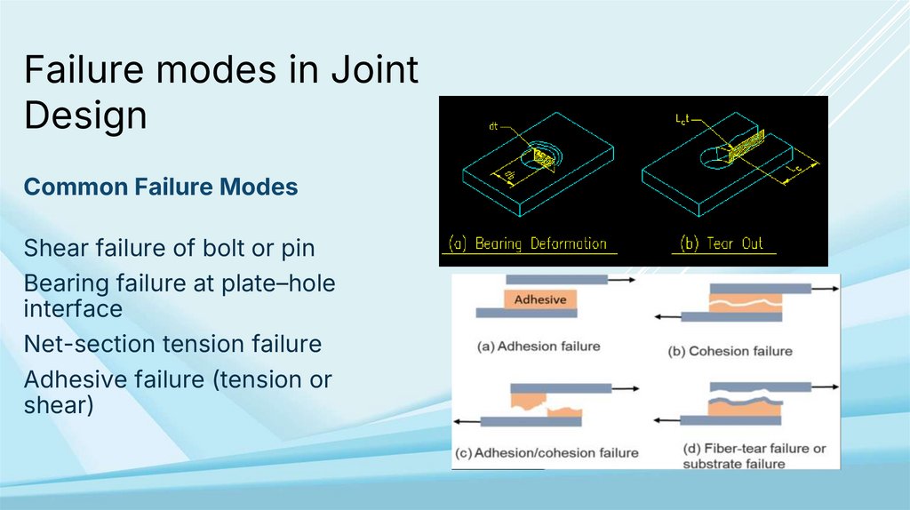
Failure modes in JointDesign
Common Failure Modes
Shear failure of bolt or pin
Bearing failure at plate–hole
interface
Net-section tension failure
Adhesive failure (tension or
shear)
5.
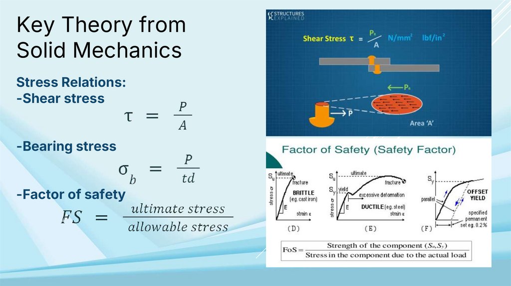
Key Theory fromSolid Mechanics
Stress Relations:
-Shear stress
-Bearing stress
-Factor of safety
6.
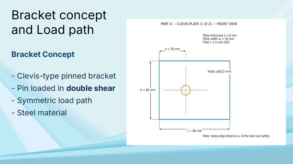
Bracket conceptand Load path
Bracket Concept
- Clevis-type pinned bracket
- Pin loaded in double shear
- Symmetric load path
- Steel material
7.
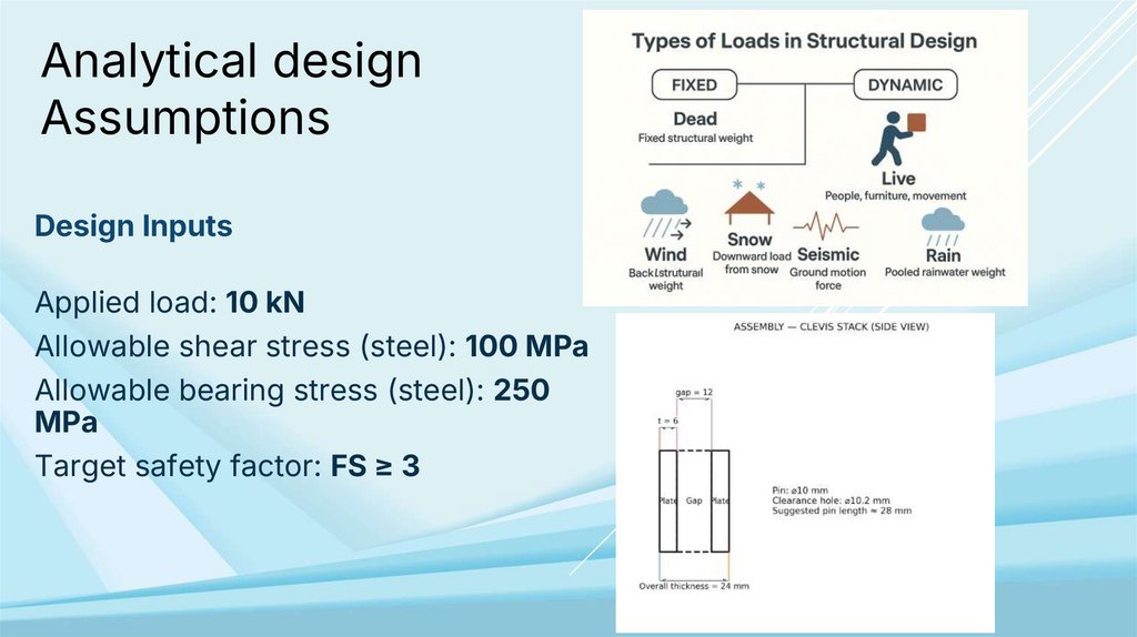
Analytical designAssumptions
Design Inputs
Applied load: 10 kN
Allowable shear stress (steel): 100 MPa
Allowable bearing stress (steel): 250
MPa
Target safety factor: FS ≥ 3
8.
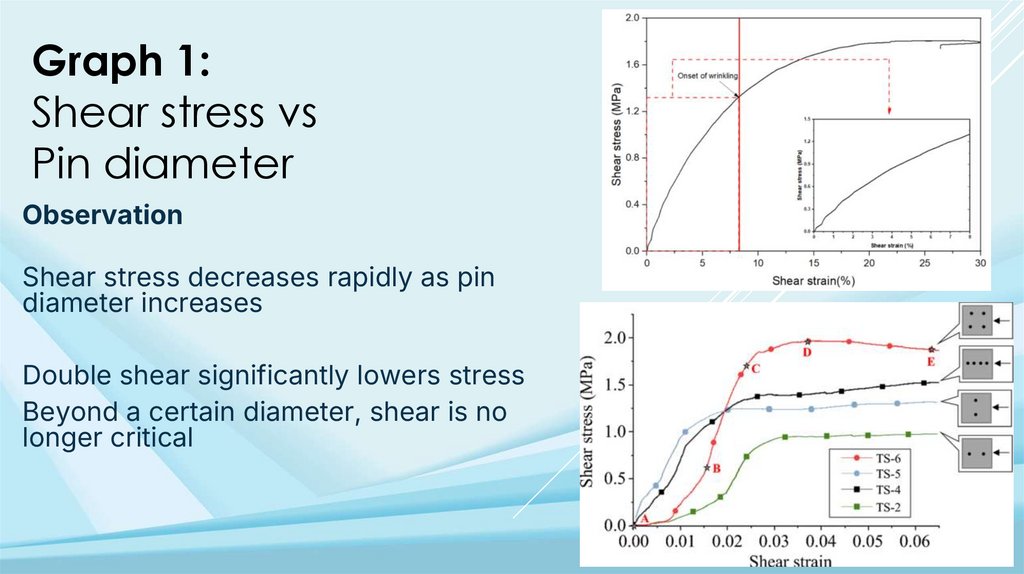
Graph 1:Shear stress vs
Pin diameter
Observation
Shear stress decreases rapidly as pin
diameter increases
Double shear significantly lowers stress
Beyond a certain diameter, shear is no
longer critical
9.
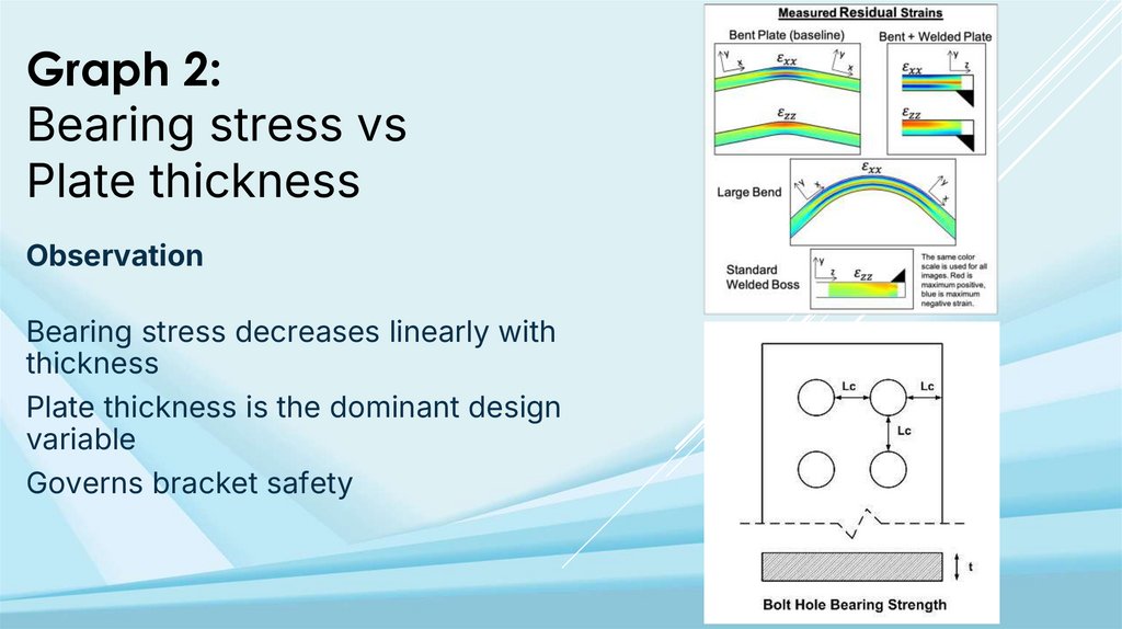
Graph 2:Bearing stress vs
Plate thickness
Observation
Bearing stress decreases linearly with
thickness
Plate thickness is the dominant design
variable
Governs bracket safety
10.
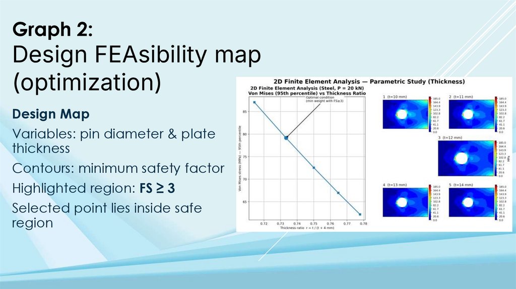
Graph 2:Design FEAsibility map
(optimization)
Design Map
Variables: pin diameter & plate
thickness
Contours: minimum safety factor
Highlighted region: FS ≥ 3
Selected point lies inside safe
region
11.
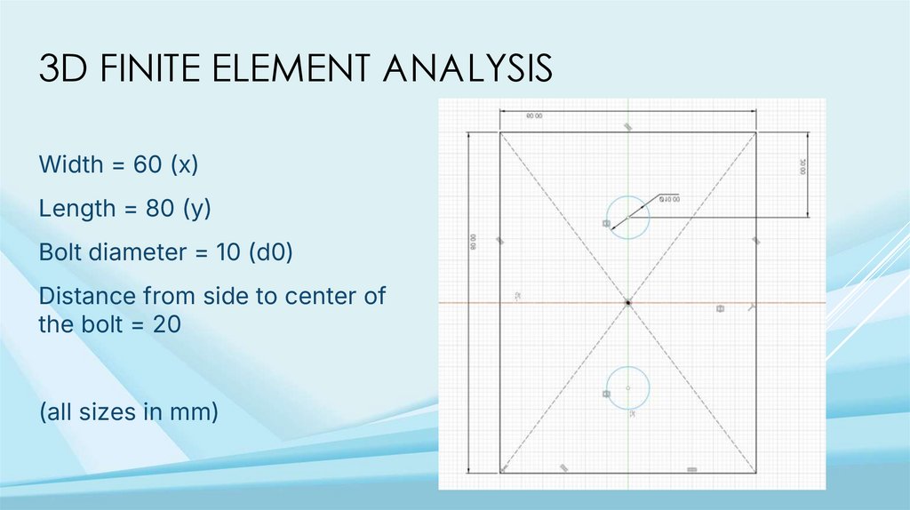
3D FINITE ELEMENT ANALYSISWidth = 60 (x)
Length = 80 (y)
Bolt diameter = 10 (d0)
Distance from side to center of
the bolt = 20
(all sizes in mm)
12.
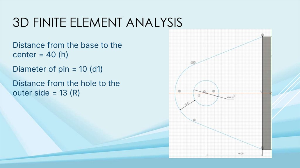
3D FINITE ELEMENT ANALYSISDistance from the base to the
center = 40 (h)
Diameter of pin = 10 (d1)
Distance from the hole to the
outer side = 13 (R)
13.
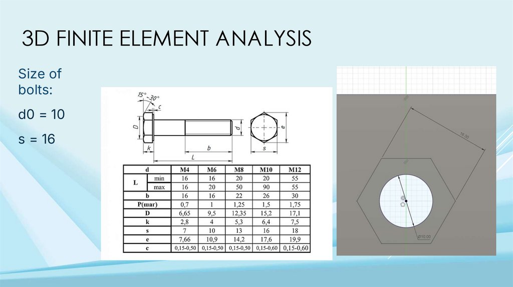
3D FINITE ELEMENT ANALYSISSize of
bolts:
d0 = 10
s = 16
14.
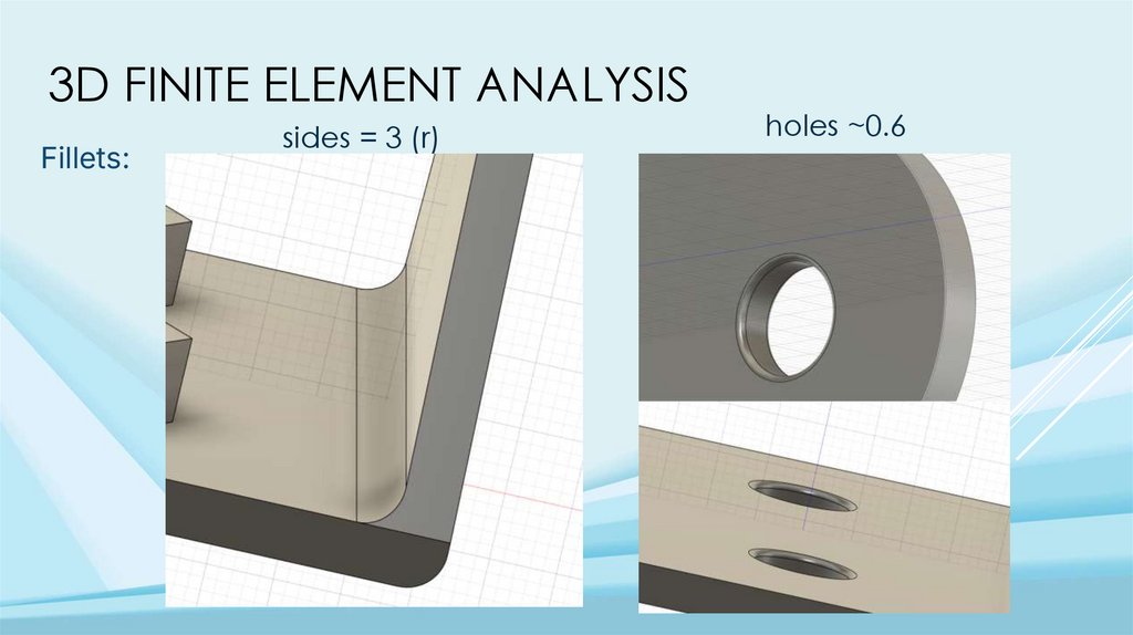
3D FINITE ELEMENT ANALYSISFillets:
sides = 3 (r)
holes ~0.6
15.
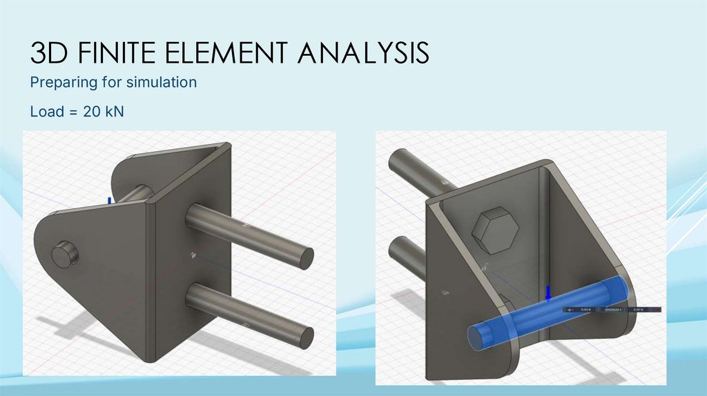
3D FINITE ELEMENT ANALYSISPreparing for simulation
Load = 20 kN
16.
3D FINITE ELEMENT ANALYSISPreparing for simulation - Creating contacts
17.
3D FINITE ELEMENT ANALYSISPreparing for simulation - Creating contacts
18.
3D FINITE ELEMENT ANALYSISPreparing for simulation - Creating contacts
19.
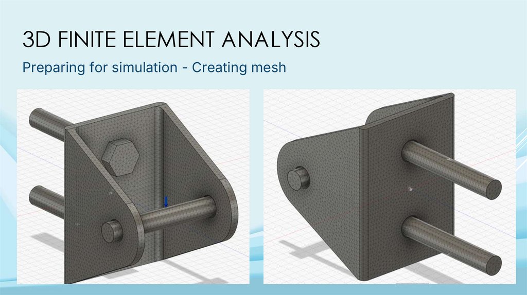
3D FINITE ELEMENT ANALYSISPreparing for simulation - Creating mesh
20.
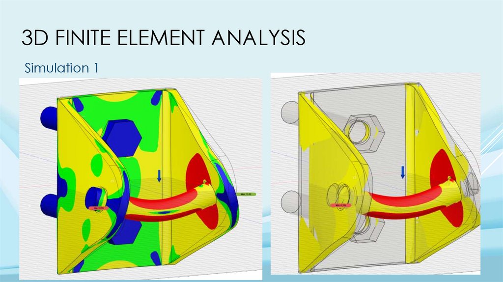
3D FINITE ELEMENT ANALYSISSimulation 1
21.
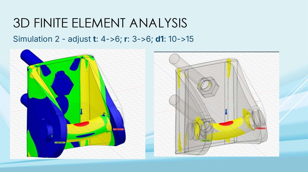
3D FINITE ELEMENT ANALYSISSimulation 2 - adjust t: 4->6; r: 3->6; d1: 10->15
22.
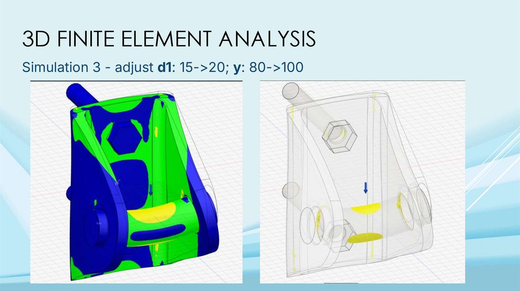
3D FINITE ELEMENT ANALYSISSimulation 3 - adjust d1: 15->20; y: 80->100
23.
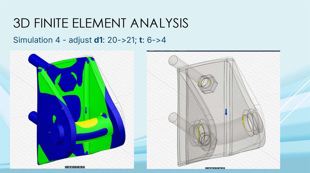
3D FINITE ELEMENT ANALYSISSimulation 4 - adjust d1: 20->21; t: 6->4
24.
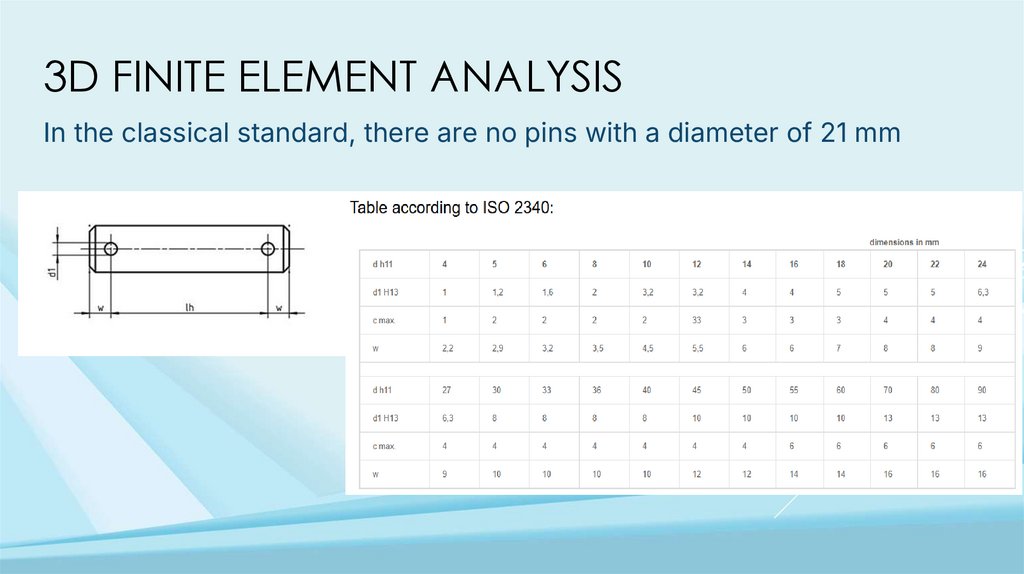
3D FINITE ELEMENT ANALYSISIn the classical standard, there are no pins with a diameter of 21 mm
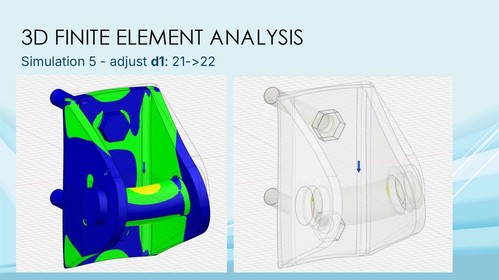
25.
3D FINITE ELEMENT ANALYSISSimulation 5 - adjust d1: 21->22
26.
3D FINITE ELEMENT ANALYSISFinal results iterative approach,
where each modification was
based on stress distribution
observed in the “Safety factor”
Base: x=60, y=100, d0=10, t=6
Sides: h=40, d1=22, r=4, R=13