


 Физика
Похожие презентации:


")


Huawei Device PT Test Instructions
1. Huawei Device PT Test Instructions
Repair Engineering Dept2.
Course objectivesAfter learning this course, you can:
What is PT, Test items of PT test
PT station setup
PT test procedure
TOP failure trouble shooting
2
HUAWEI TECHNOLOGIES CO., LTD.
2
Huawei Confidential
3.
01What is PT
目录
02
PT Station Setup Diagram
Contents
03
PT Test procedure
04
PT test items and Logs Explanation
05
Trouble Shooting
4.
01 What is PTPT testing :
Monitoring power on current/idle current/leak current of phone, changing the phone’s status(power
on/sleep/power off) by commands via USB circuit , Programmable power supply(Keithley 2303/2306 or
Agilent66311B/66319D) as power source.
There are three modes for PT testing, the details refers to PT instructions of each model
Mode 1: Testing with jig
Mode 2: Testing with fake battery
Mode 3: Testing with Jig box
4
5.
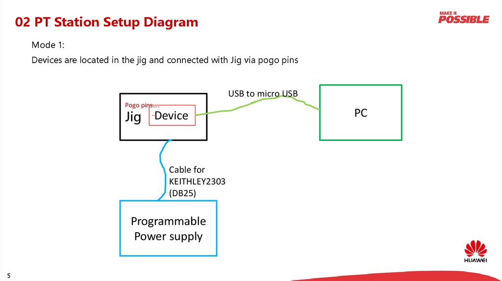
02 PT Station Setup DiagramMode 1:
Devices are located in the jig and connected with Jig via pogo pins
USB to micro USB
Pogo pins….
…
Jig
Device
Cable for
KEITHLEY2303
(DB25)
Programmable
Power supply
5
PC
6.
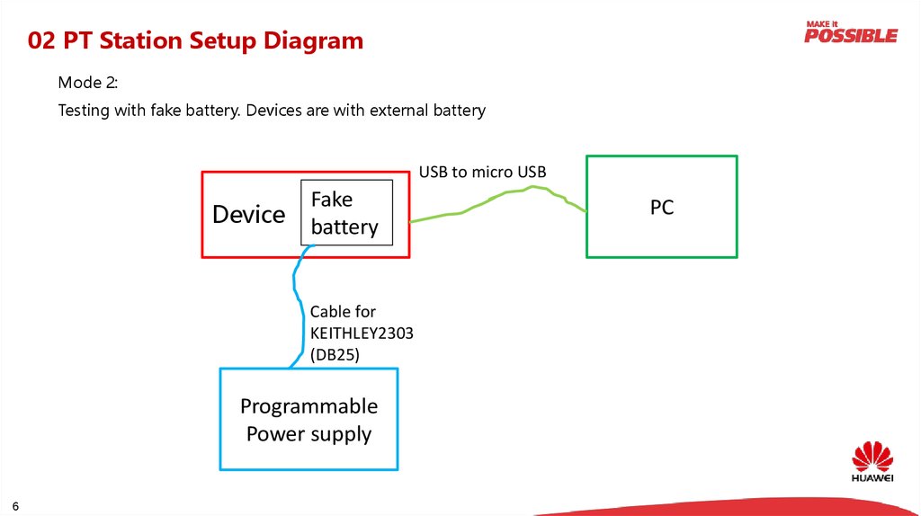
02 PT Station Setup DiagramMode 2:
Testing with fake battery. Devices are with external battery
USB to micro USB
Device
Fake
battery
Cable for
KEITHLEY2303
(DB25)
Programmable
Power supply
6
PC
7.
02 PT Station Setup DiagramMode 3:
Adapter 12V/2A,
item code:02220597
Testing with Jigbox
Device
Micro2Mini USB
cable,item
code:99052KAK
USB to micro USB
Jigbox
Item
code:02451005
Cable for
KEITHLEY2303
(DB25)
Programmable
Power supply
7
PC
8.
03 PT Test procedureSetup the
station
Launch the
test tool
and set the
parameters
Download the tool from“diagnose
and test tool”, Operation Manual in
in “Maintenance Document”
8
Testing
Initialization
Power on
and search
the port
Verify
Manufacturin
g info
Power on
current and
voltage test
Charging test
Idle current
test
END
Leak current
test
9.
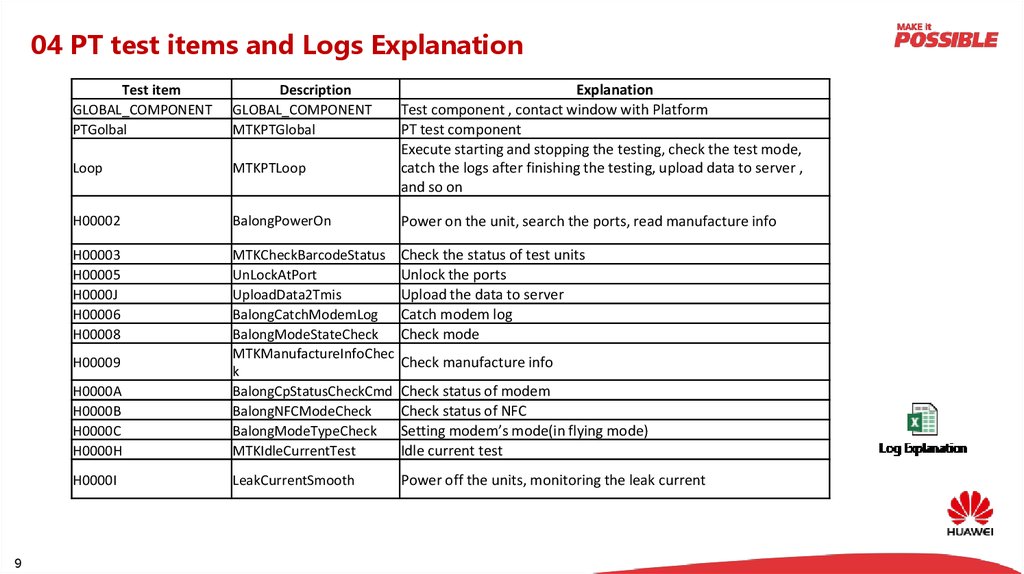
04 PT test items and Logs ExplanationDescription
GLOBAL_COMPONENT
MTKPTGlobal
Loop
MTKPTLoop
H00002
BalongPowerOn
Power on the unit, search the ports, read manufacture info
H00003
H00005
H0000J
H00006
H00008
Check the status of test units
Unlock the ports
Upload the data to server
Catch modem log
Check mode
H0000A
H0000B
H0000C
H0000H
MTKCheckBarcodeStatus
UnLockAtPort
UploadData2Tmis
BalongCatchModemLog
BalongModeStateCheck
MTKManufactureInfoChec
k
BalongCpStatusCheckCmd
BalongNFCModeCheck
BalongModeTypeCheck
MTKIdleCurrentTest
H0000I
LeakCurrentSmooth
Power off the units, monitoring the leak current
H00009
9
Explanation
Test component , contact window with Platform
PT test component
Execute starting and stopping the testing, check the test mode,
catch the logs after finishing the testing, upload data to server ,
and so on
Test item
GLOBAL_COMPONENT
PTGolbal
Check manufacture info
Check status of modem
Check status of NFC
Setting modem’s mode(in flying mode)
Idle current test
10.
05 Trouble ShootingNormal process:
PT Fail
Test again after
rebuilding PT station
PASS
Check the test environment,
such as PC, fixture, cables, etc.
Fail
Take a known good unit
to do PT test
Fail
Station setup issue, swap
fixture/PC/cables to find the
root cause
PASS
Test again after replace
LCD/TP/Housing/battery
10
Fail
According to logs, do analysis on
PCBA, replace faulty components
to fix the issue
PASS
LCD/TP/Housing/Battery issue
END
11.
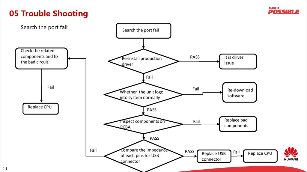
05 Trouble ShootingSearch the port fail:
Search the port fail
Check the related
components and fix
the bad circuit.
Re-install production
driver
PASS
It is driver
issue
Fail
Fail
Whether the unit logo
into system normally
Replace CPU
Fail
Re-download
software
PASS
Inspect components on
PCBA
Fail
Replace bad
components
PASS
Fail
11
Compare the impedance
of each pins for USB
connector
PASS
Replace USB
connector
Fail
Replace CPU
12.
05 Trouble ShootingIdle Current fail:
Idle current fail
Test again after
rebuilding PT station
PASS
Check the test environment,
such as PC, fixture, cables, etc.
Fail
Test again after replace
LCD/TP/Housing/battery
PASS
LCD/TP/Housing/Battery
issue
Fail
Replace bad
components
Fail
Inspect components on
PCBA
PASS
Replace PMU
12
Pass
Power on PCBA by power
supply, and make PCBA sleep,
measure voltage for each
module(Wifi IC, RF IC, LCD,
Audio, etc.)
Fail
Check related components with
suspect module, and replace
bad components
Replace
suspect
module
13.
05 Trouble ShootingIdle current Trouble shooting:
Step 1: Power on the MLB by programmable power supply 1, and then sleep the MLB
Step 2: Feed voltage 0.2V higher than it which should be on when sleep, such as 1.8V, 0.9V, 3.3V, etc.
Step 3: Check the current of power supply 1, if the current changes , there are something wrong with the
circuit
13
14.
05 Trouble ShootingLeak Current fail:
Leak current fail
Test again after
rebuilding PT station
PASS
Check the test environment,
such as PC, fixture, cables, etc.
Fail
PASS
Test again after replace
LCD/TP/Housing/battery
LCD/TP/Housing/Battery
issue
Fail
Inspect components on
PCBA
Fail
Replace bad
components
PASS
Try to replace RF IC
14
Pass
Compare the impedance
of power pins to
GND,such as
VBATT,VBAT_SYS
Fail
Refer to circuit diagram, remove
suspect components one by one or
use thermal imager to locate the
faulty component, then fix the issue
15.
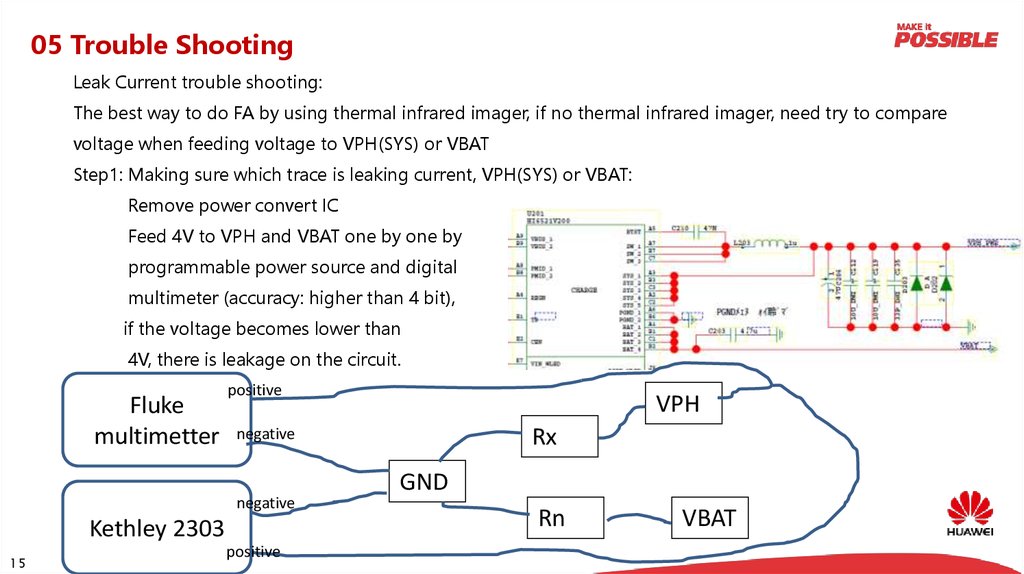
05 Trouble ShootingLeak Current trouble shooting:
The best way to do FA by using thermal infrared imager, if no thermal infrared imager, need try to compare
voltage when feeding voltage to VPH(SYS) or VBAT
Step1: Making sure which trace is leaking current, VPH(SYS) or VBAT:
Remove power convert IC
Feed 4V to VPH and VBAT one by one by
programmable power source and digital
multimeter (accuracy: higher than 4 bit),
if the voltage becomes lower than
4V, there is leakage on the circuit.
Fluke
multimetter
positive
Rx
negative
negative
Kethley 2303
15
VPH
positive
GND
Rn
VBAT
16.
05 Trouble ShootingStep2: if VBAT is leakage current. Feeding 4V to VBAT by positive, and measure input of Un(can be IC , resister,
capacitor, etc, R is resistance of PCB line) by negative
If U3 is bad and leakage current, V3(Vpositive-Vnegative) will be the biggest one.
VBAT
R
positive
R
R
Fluke
multimetter negative
R
R
U1
R
R
U2
R
R
U3
R
U4
Un
positive
Kethley 2303
negative
GND
16
R
R
R
R
R
R
R
R
R
R
17.
05 Trouble ShootingCharging fail:
Charging fail
Replace bad components
Fail
Check converter IC for
VCHG and related
components
Pass
Replace converter IC
for VCHG
Fail
Replace USB
connector
Fail
Replace PMU
17
Test again after
rebuilding PT station
PASS
Check the test environment,
such as PC, fixture, cables, etc.
Fail
PASS
Test again after replace
LCD/TP/Housing/battery
LCD/TP/Housing/Battery
issue
Fail
Inspect components on
PCBA(battery connector,
pogo pins, etc)
PASS
Power on PCBA by
power supply, check
VCHG is 5V?
Fail
YES
Replace bad
components
Replace PMU
18.
Thank youwww.huawei.com
Copyright©2015 Huawei Technologies Co., Ltd. All Rights Reserved.
The information in this document may contain predictive statements including, without limitation, statements
regarding the future financial and operating results, future product portfolio, new technology, etc. There are a
number of factors that could cause actual results and developments to differ materially from those expressed or
implied in the predictive statements. Therefore, such information is provided for reference purpose only and
constitutes neither an offer nor an acceptance. Huawei may change the information at any time without notice.