
")
")


 step disturbance input (b) step reference input")
 basic system; (b) PD control; (c) PID control")


 Физика
 Электроника
Похожие презентации:


Review, PID controller
1.
Review, PID ControllerMd Hazrat Ali
Department of Mechanical Engineering
School of Engineering,
Nazarbayev University
2.
Today’s Quote:“Live as if you were to die tomorrow. Learn as if you were to
live forever.”
― Mahatma Gandhi
3. Steady State Error (ess)
Steady-state error is defined as the difference between the input(command) and the output of a system in the limit as time goes to
infinity (i.e. when the response has reached steady state). The
steady-state error will depend on the type of input (step, ramp, etc.)
as well as the system type (0, I, or II).
Note: Steady-state error analysis is only useful for stable
systems. You should always check the system for stability before
performing a steady-state error analysis.
4. Steady State Error (ess)
5.
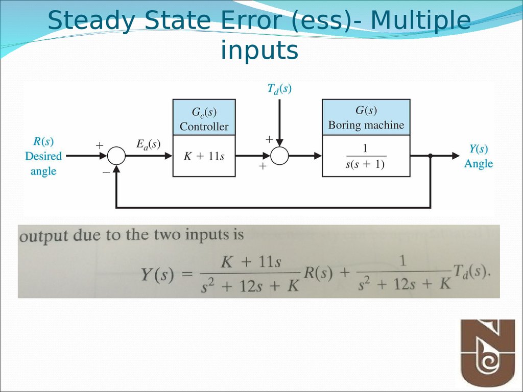
Steady State Error (ess)- Multipleinputs
6.
Classical ControllerPID Controller7.
IntroductionMore than half of the industrial controllers in use today utilize
PID or modified PID control schemes.
When the mathematical model of the plant is not known and
therefore analytical design methods cannot be used, PID
controls prove to be most useful.
Design PID control
Know mathematical model various design techniques
Plant is complicated, can’t obtain mathematical model
experimental approaches to the tuning of PID controllers
8. PID Control
PID ControlA closed loop (feedback) control system, generally with
Single InputSingle Output (SISO)
A portion of the signal being fed back is:
Proportional to the signal (P)
Proportional to integral of the signal (I)
Proportional to the derivative of the signal (D)
9. When PID Control is Used
PID control works well on SISO systems of 2nd Order, where adesired Set Point can be supplied to the system control input
PID control handles step changes well to the Set Point
especially when :
Fast Rise Times
Little or No Overshoot
Fast settling Times
Zero Steady State Error
PID controllers are often fine tuned on-site, using established
guidelines
10. Output equation of PID controller in time domain
11.
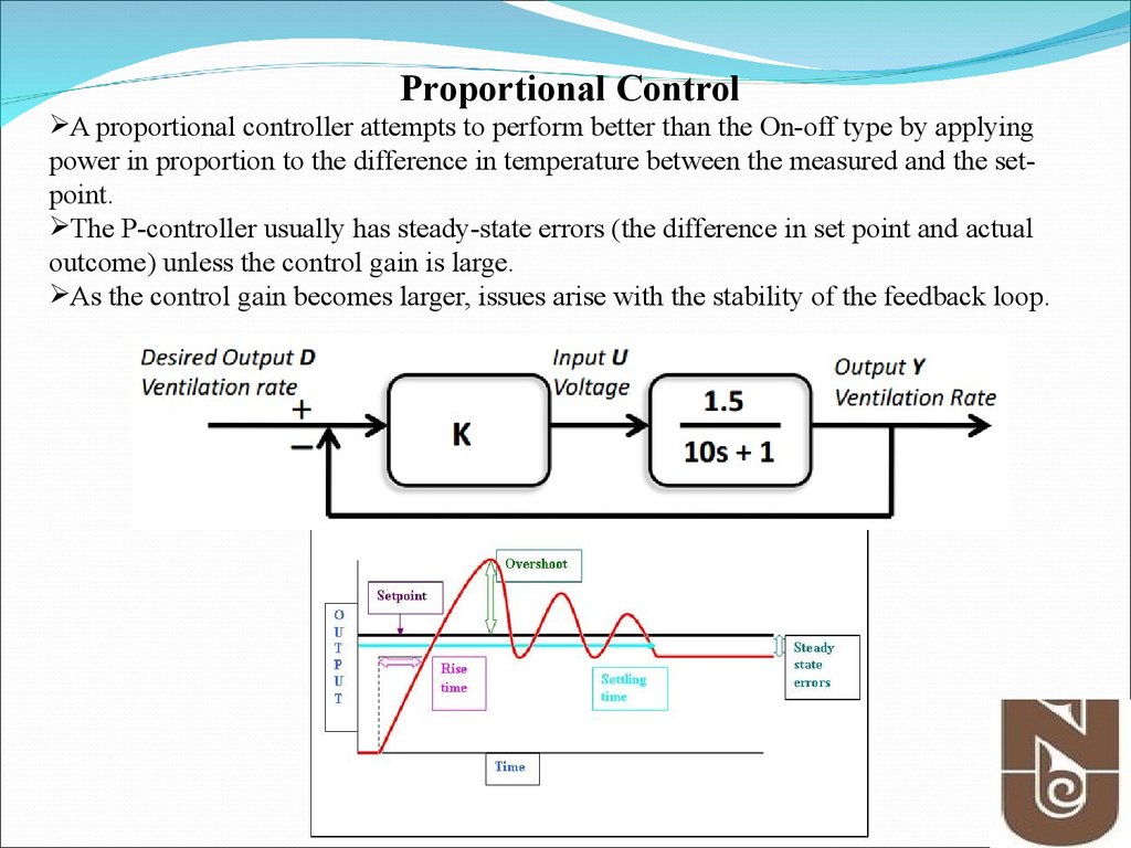
Proportional ControlA proportional controller attempts to perform better than the On-off type by applying
power in proportion to the difference in temperature between the measured and the setpoint.
The P-controller usually has steady-state errors (the difference in set point and actual
outcome) unless the control gain is large.
As the control gain becomes larger, issues arise with the stability of the feedback loop.
12.
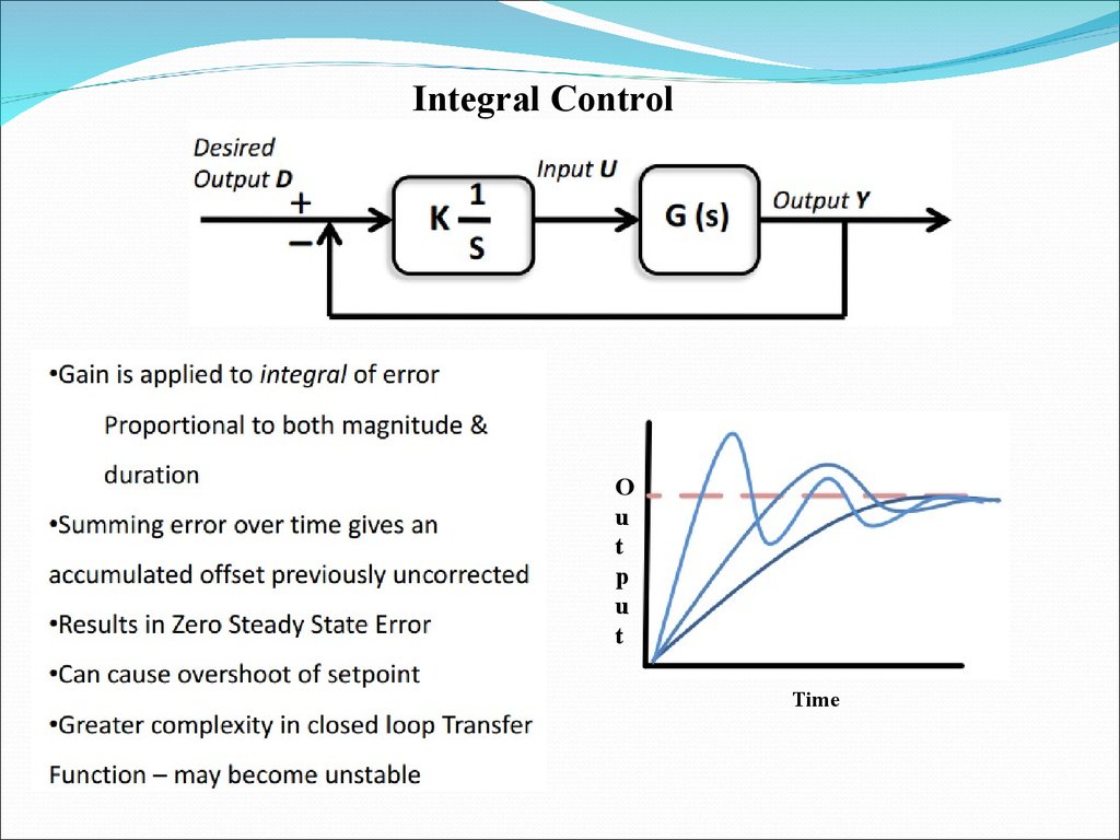
Integral ControlO
u
t
p
u
t
Time
13.
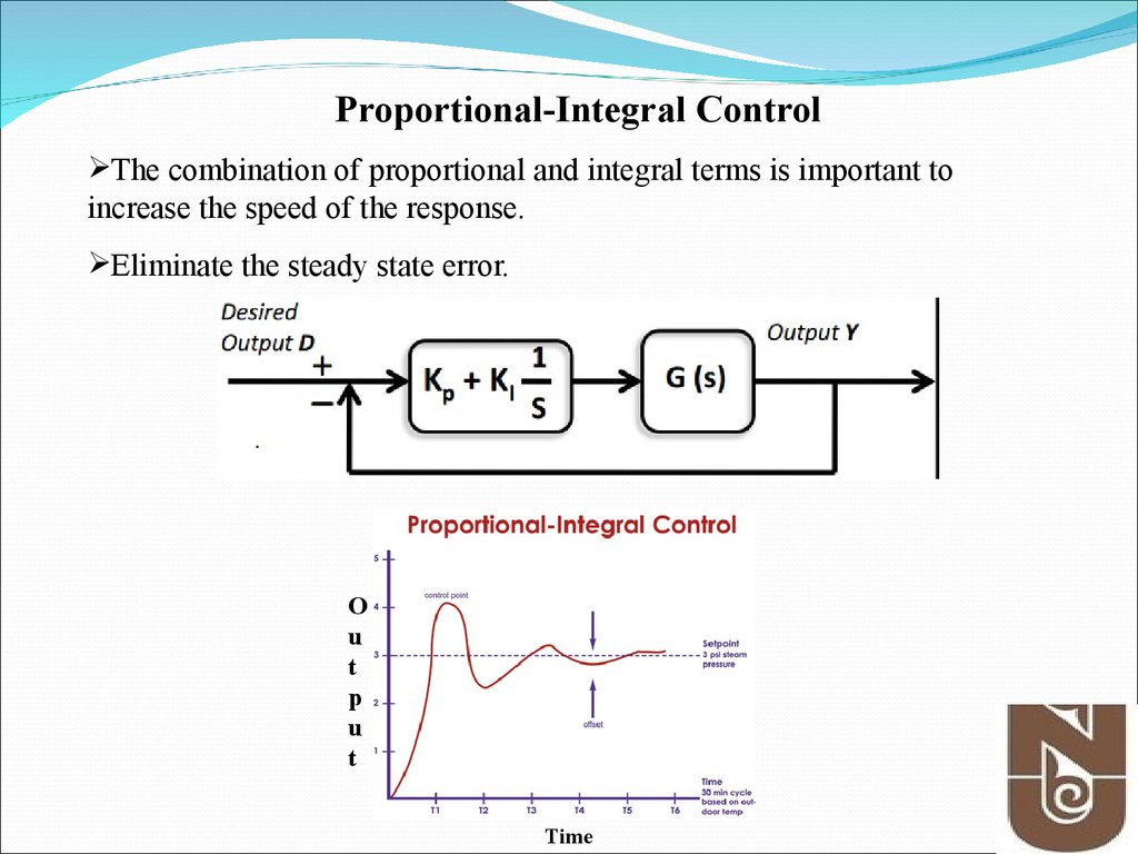
Proportional-Integral ControlThe combination of proportional and integral terms is important to
increase the speed of the response.
Eliminate the steady state error.
O
u
t
p
u
t
Time
14.
15.
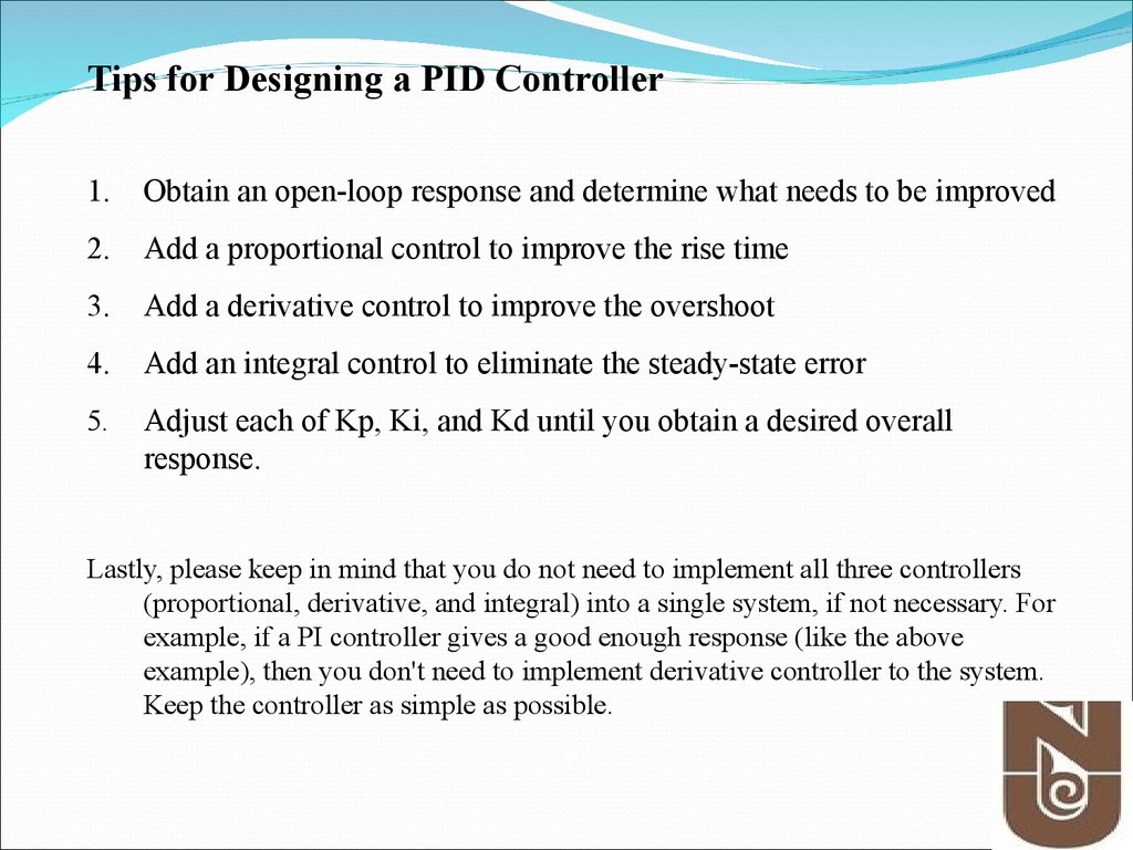
Tips for Designing a PID Controller1.
Obtain an open-loop response and determine what needs to be improved
2.
Add a proportional control to improve the rise time
3.
Add a derivative control to improve the overshoot
4.
Add an integral control to eliminate the steady-state error
5.
Adjust each of Kp, Ki, and Kd until you obtain a desired overall
response.
Lastly, please keep in mind that you do not need to implement all three controllers
(proportional, derivative, and integral) into a single system, if not necessary. For
example, if a PI controller gives a good enough response (like the above
example), then you don't need to implement derivative controller to the system.
Keep the controller as simple as possible.
16.
PID Controller(Conti… )
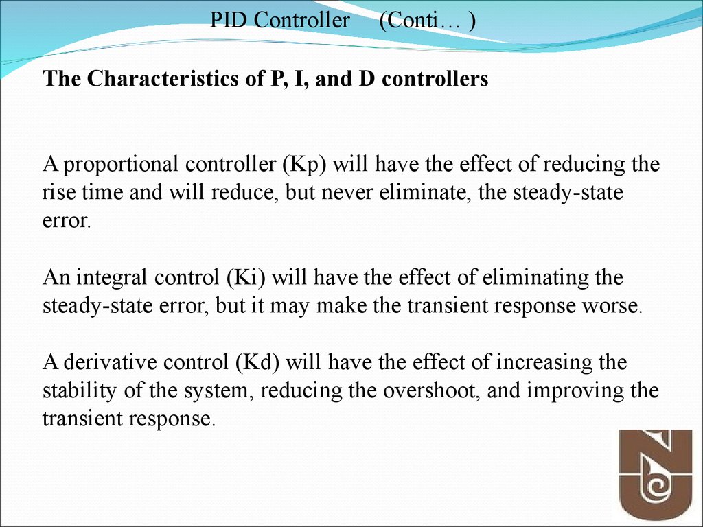
The Characteristics of P, I, and D controllers
A proportional controller (Kp) will have the effect of reducing the
rise time and will reduce, but never eliminate, the steady-state
error.
An integral control (Ki) will have the effect of eliminating the
steady-state error, but it may make the transient response worse.
A derivative control (Kd) will have the effect of increasing the
stability of the system, reducing the overshoot, and improving the
transient response.
17.
PID Controller(Conti… )
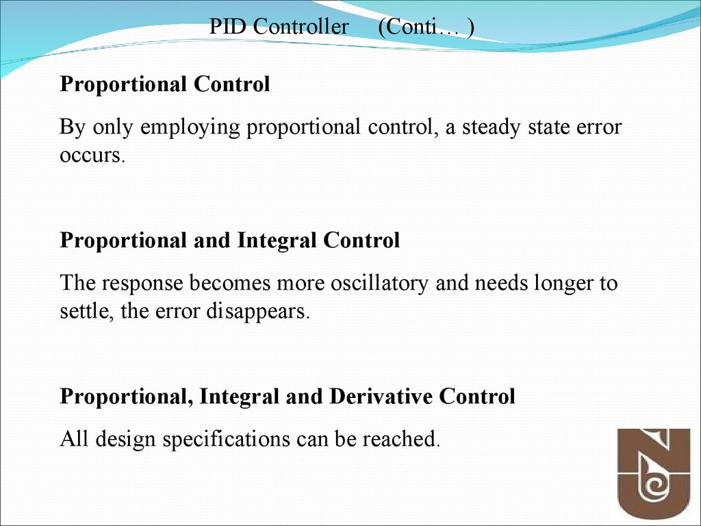
Proportional Control
By only employing proportional control, a steady state error
occurs.
Proportional and Integral Control
The response becomes more oscillatory and needs longer to
settle, the error disappears.
Proportional, Integral and Derivative Control
All design specifications can be reached.
18.
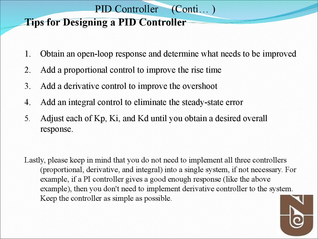
PID Controller (Conti… )Tips for Designing a PID Controller
1.
Obtain an open-loop response and determine what needs to be improved
2.
Add a proportional control to improve the rise time
3.
Add a derivative control to improve the overshoot
4.
Add an integral control to eliminate the steady-state error
5.
Adjust each of Kp, Ki, and Kd until you obtain a desired overall
response.
Lastly, please keep in mind that you do not need to implement all three controllers
(proportional, derivative, and integral) into a single system, if not necessary. For
example, if a PI controller gives a good enough response (like the above
example), then you don't need to implement derivative controller to the system.
Keep the controller as simple as possible.
19.
PID Controller(Conti… )
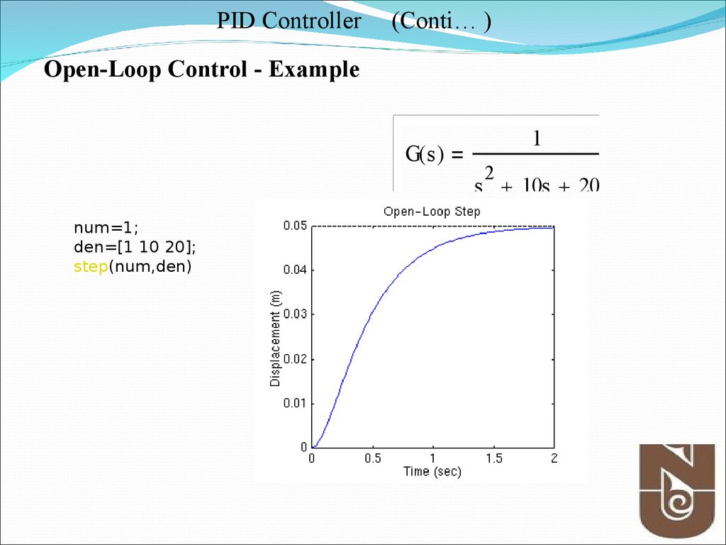
Open-Loop Control - Example
G( s )
1
2
s 10s 20
num=1;
den=[1 10 20];
step(num,den)
20.
PID Controller(Conti… )
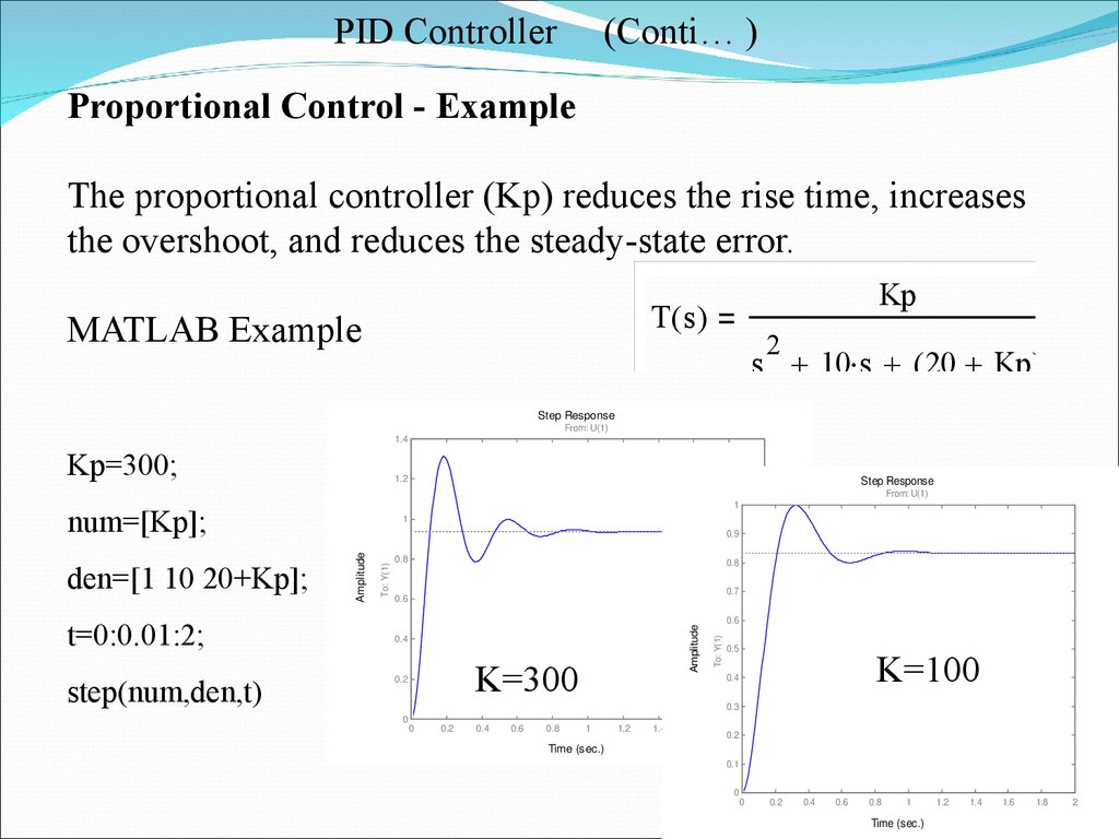
Proportional Control - Example
The proportional controller (Kp) reduces the rise time, increases
the overshoot, and reduces the steady-state error.
Kp
T( s )
MATLAB Example
2
s 10 s ( 20 Kp )
Step Response
From: U(1)
1.4
Kp=300;
1.2
num=[Kp];
step(num,den,t)
0.9
0.8
0.8
0.7
0.6
0.4
K=300
0.2
0.6
To: Y(1)
Amplitude
t=0:0.01:2;
From: U(1)
1
To: Y(1)
den=[1 10 20+Kp];
Step Response
1
Amplitude
0.5
K=100
0.4
0.3
0
0
0.2
0.4
0.6
0.8
1
1.2
1.4
1.6
1.8
0.2
2
Time (sec.)
0.1
0
0
0.2
0.4
0.6
0.8
1
Time (sec.)
1.2
1.4
1.6
1.8
2
21.
PID Controller(Conti… )
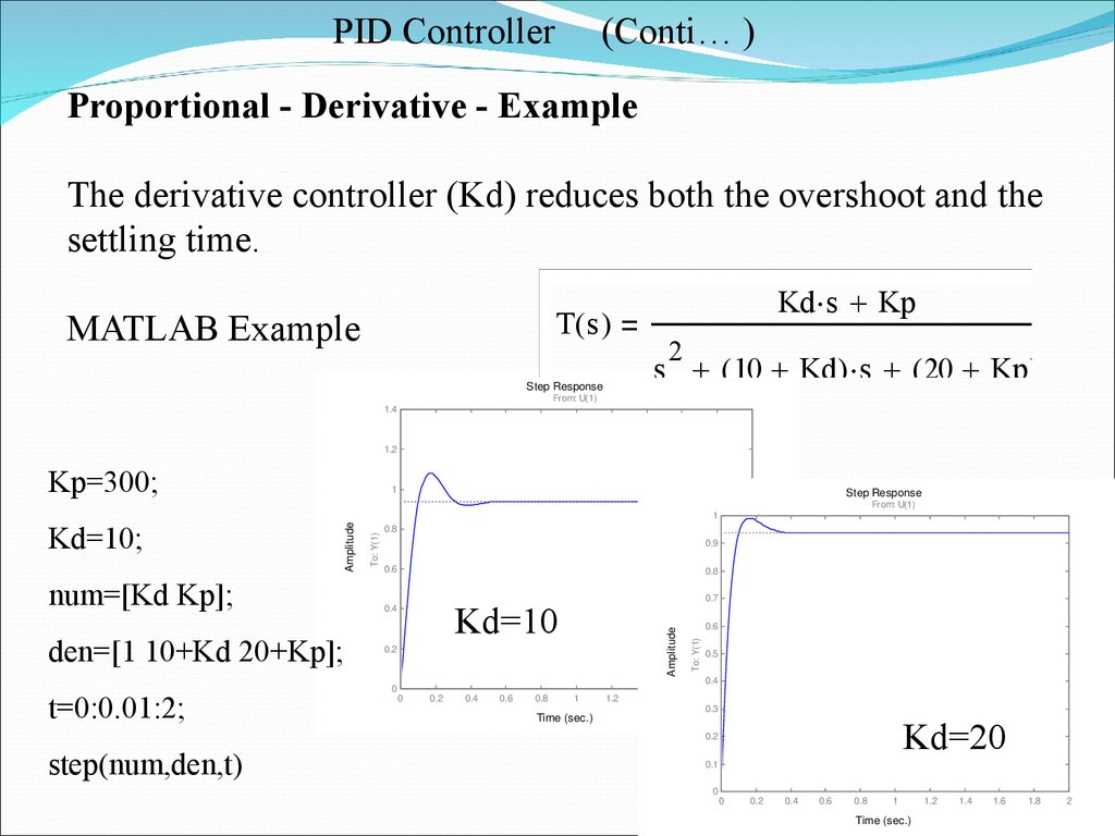
Proportional - Derivative - Example
The derivative controller (Kd) reduces both the overshoot and the
settling time.
Kd s Kp
T( s )
MATLAB Example
2
s ( 10 Kd ) s ( 20 Kp )
Step Response
From: U(1)
1.4
1.2
Kp=300;
From: U(1)
To: Y(1)
0.9
0.6
0.8
0.7
Kd=10
0.4
0.2
0
0
0.2
0.4
0.6
0.8
1
Time (sec.)
1.2
1.4
1.6
0.6
To: Y(1)
den=[1 10+Kd 20+Kp];
0.8
Amplitude
num=[Kd Kp];
t=0:0.01:2;
Step Response
1
Amplitude
Kd=10;
1
0.5
0.4
1.8
0.3
2
Kd=20
0.2
step(num,den,t)
0.1
0
0
0.2
0.4
0.6
0.8
1
Time (sec.)
1.2
1.4
1.6
1.8
2
22.
PID Controller(Conti… )
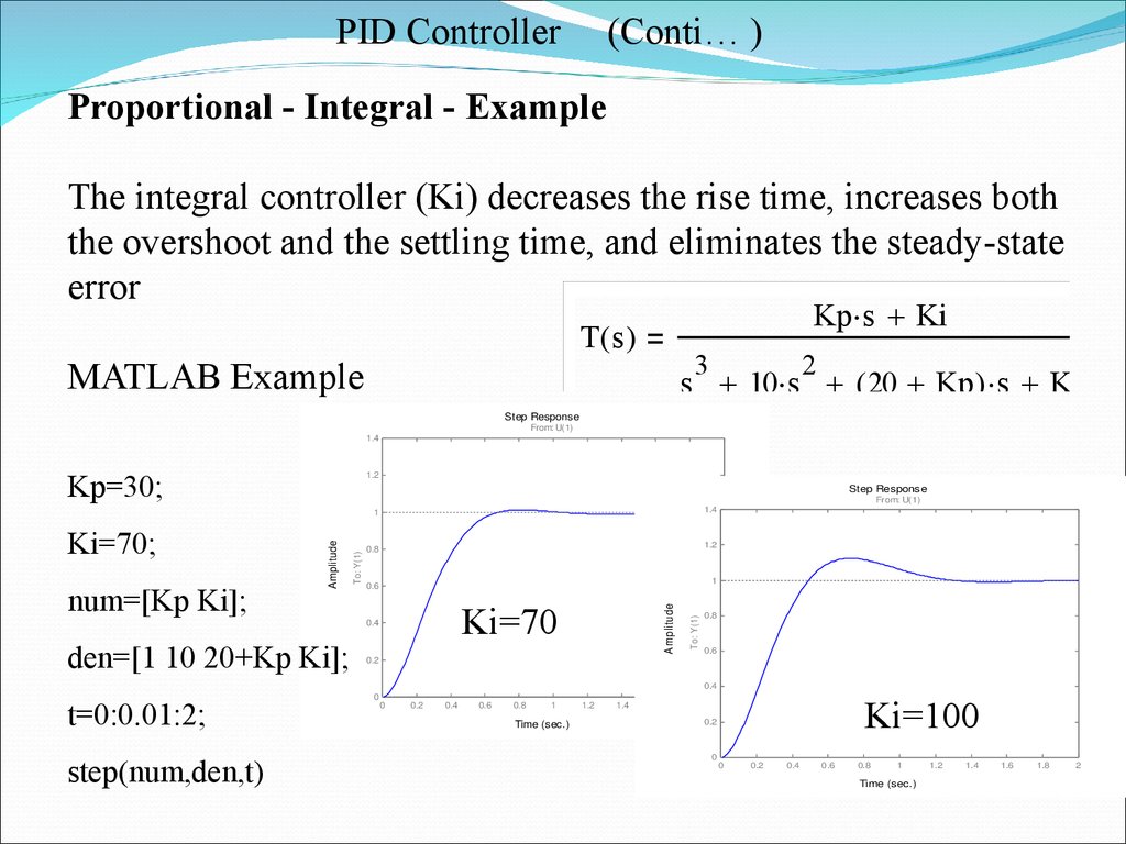
Proportional - Integral - Example
The integral controller (Ki) decreases the rise time, increases both
the overshoot and the settling time, and eliminates the steady-state
error
Kp s Ki
T( s )
3
MATLAB Example
2
s 10 s ( 20 Kp ) s Ki
Step Response
From: U(1)
1.4
Kp=30;
1.2
Step Response
t=0:0.01:2;
step(num,den,t)
1.2
0.8
1
Ki=70
0.4
To: Y(1)
0.6
A m plitude
den=[1 10 20+Kp Ki];
To: Y(1)
num=[Kp Ki];
Amplitude
1
Ki=70;
0.2
0
From: U(1)
1.4
0.8
0.6
0.4
0
0.2
0.4
0.6
0.8
1
Time (sec.)
1.2
1.4
1.6
1.8
Ki=100
2
0.2
0
0
0.2
0.4
0.6
0.8
1
Time (sec.)
1.2
1.4
1.6
1.8
2
23.
PID Controller(Conti… )
The Characteristics of P, I, and D controllers
CL RESPONSE
RISE TIME
OVERSHOOT
SETTLING TIME
S-S ERROR
Kp
Decrease
Increase
Small Change
Decrease
Ki
Decrease
Increase
Increase
Eliminate
Kd
Small Change
Decrease
Decrease
Small Change
24. Figure 4.9 Responses of P, PI, and PID control to (a) step disturbance input (b) step reference input
PID Controller(Conti… )
Figure 4.9 Responses of P, PI, and PID control to (a) step disturbance input (b) step reference input
25. Figure 4.10 Model of a satellite attitude control: (a) basic system; (b) PD control; (c) PID control
PID Controller(Conti… )
Figure 4.10 Model of a satellite attitude control: (a) basic system; (b) PD control; (c) PID control
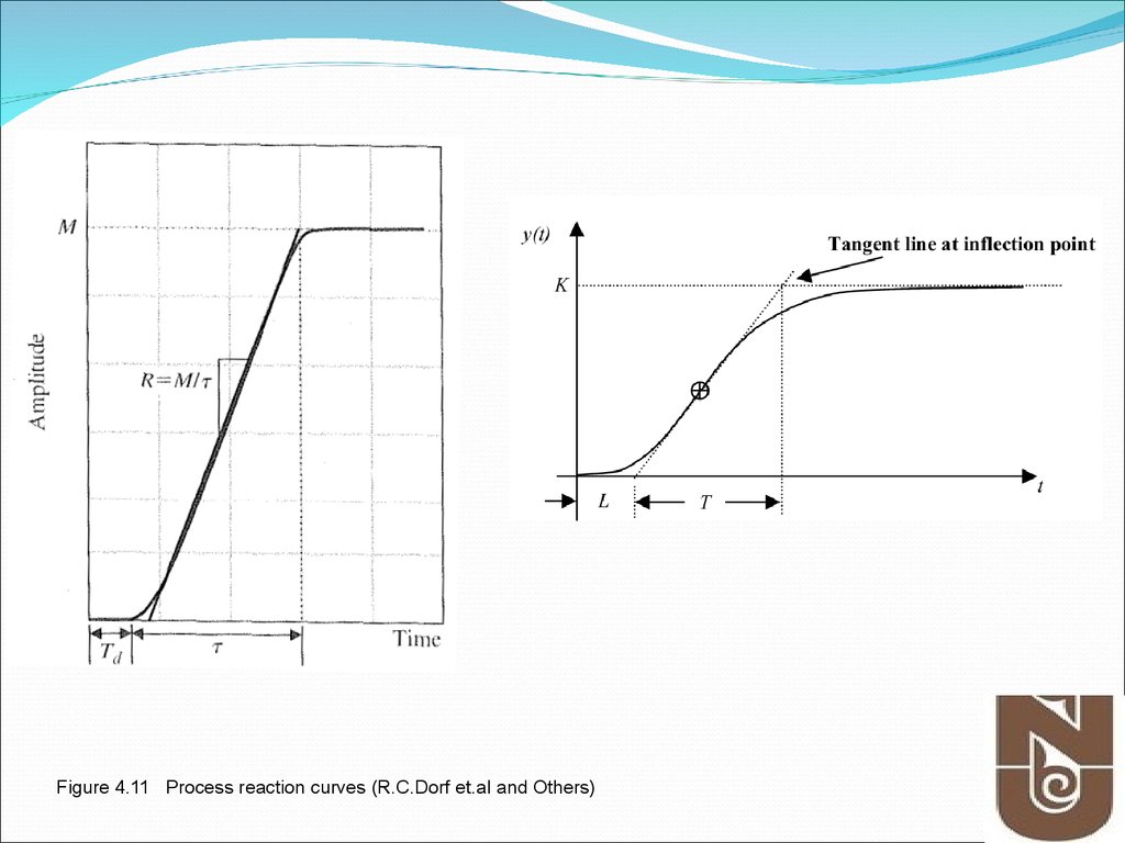
26. Figure 4.11 Process reaction curve
PID ControllerFigure 4.11 Process reaction curve
27.
Figure 4.11 Process reaction curves (R.C.Dorf et.al and Others)28. Figure 4.12 Quarter decay ratio
PID Controller- Ziegler Method #1Figure 4.12 Quarter decay ratio
29. TABLE 4.2
PID ControllerTABLE 4.2
(Conti… )
30. Figure 4.13 Determination of ultimate gain and period
PID Controller- Ziegler Method #2Figure 4.13 Determination of ultimate gain and period
31. Figure 4.14 Neutrally stable system
PID ControllerFigure 4.14 Neutrally stable system
(Conti… )
32. TABLE 4.3
PID ControllerTABLE 4.3
(Conti… )
33. Further Reading
Franklin, et. al., Chapter 4Section 4.3
Richard C. Dorf et.al, Chapter 6,
Chapter 6.2