


 Электроника
Похожие презентации:


")

Advanced Design Lab: CCD History
1. Advanced Design Lab: CCD History
Special Astrophysical Observatory, 20052. Activities in 1980-2005
SAOActivities in 1980-2005
Development of four generations of CCD Controllers
Development of LN2 Cameras for various observation purposes
Production of about 30 CCD Systems for 6-m telescope and other
observatories
Research and development of methods of CCD readout noise
minimizing and photometric precision maximizing
Investigation and testing of numerous SITe, E2V, Lick, TI, Atmel and
others CCDs
Climatic testing of CCD systems
Advanced Design Lab
3. 1980s: First CCDs
SAO1980s: First CCDs
1981. The first CCD Camera with
320 x 288 front illuminated surface
channel CCD
1984. CCD Camera with 512 x 576
front illuminated surface channel
CCD
Advanced Design Lab
4. 1980s: First CCDs
SAO1980s: First CCDs
1984. Generation I CCD Controller
with control computer
1985. First application of bit-slice
processor in Generation II CCD
Controller
Advanced Design Lab
5. 1980s: First CCDs
SAO1980s: First CCDs
1985. LN2 CCD Camera with 520 x
580 front illuminated CCD with
buried channel
1985. Generation II CCD Controller
based on bit-slice processor
Advanced Design Lab
6. 1990s: Low noise CCDs
SAO1990s: Low noise CCDs
1994. Generation III CCD
Controller with embedded Intel
8080 microcomputer
1994. LN2 CCD Cameras with 1K x
1K and 2K x 2K CCDs
Advanced Design Lab
7. 2000s: Ultra low noise CCDs
SAO2000s: Ultra low noise CCDs
2000. DINACON - New Generation
DSP based CCD Controller for ultra
low noise and high precision
imaging
2000. LN2 Dewars for up to 4K x
4K CCDs
Advanced Design Lab
8. DINACON: New imaging concept
SAODINACON: New imaging concept
Novelty
• Optimal filtering of video
signal
• Digital correction of bias and
gain instabilities and
non-linearity
• Flexible multiprocessor
architecture with
multitasking RTOS
Advantages
• Minimum readout noise
• Very high stability and
linearity
of CCD System transfer
characteristic
• High dynamical range
• Easy to control the complex
mosaic and infrared
detectors
Generation IV CCD controller DINACON: DSP based Intelligent Array Controller
Advanced Design Lab
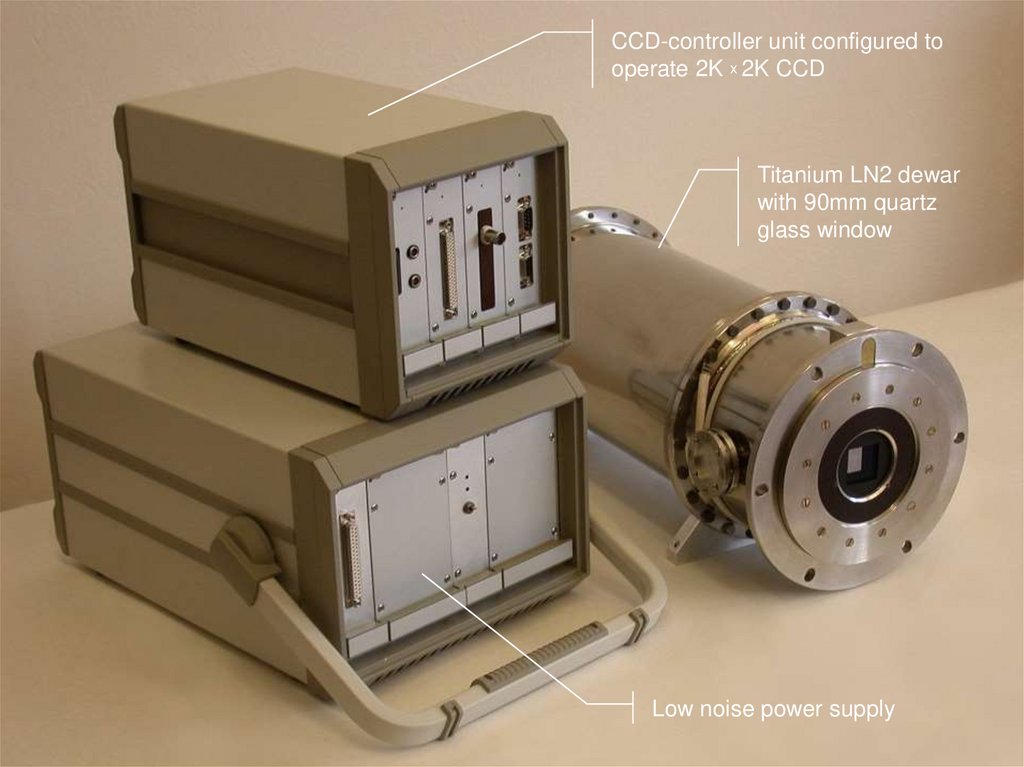
9.
CCD-controller unit configured tooperate 2K x 2K CCD
Titanium LN2 dewar
with 90mm quartz
glass window
Low noise power supply
10. Typical single processor CCD-system
SAOTypical single processor CCD-system
CCD-system
CCD 1
Advantages
Analog
videoprocessor
- relative simplicity
- multichannel operations
...
CCD n
Analog
videoprocessor
Clock driver
Sequencer
DSP
Interface
System bus
Clock driver
Limitations
-
incomplete noise filtering
noisy system bus
limited number of channels (n<16)
low level of flexibility and
intelligent functions
Host
computer
Advanced Design Lab
11. SAO’s DSP-based CCD-system
SAOSAO’s DSP-based CCD-system
CCD-system
CCD 1
Advantages
Digital
DSP
videoprocessor
Sequencer/
Clock drivers
DSP
...
CCD n
- ultralow noise through matched filtering
- no noisy system bus
- higher precision and accuracy
- flexible star- or- tree-type topology
- number of channels up to 32
- high level of intelligent functions
Digital
DSP
videoprocessor
Sequencer/
Clock drivers
Interface
DSP
DSP
Fast
Serial
links
Host
computer
Advanced Design Lab
12. Why need matched filtering?
SAOWhy need matched filtering?
1/f noise:
matched filtering is
up to 30 % more
effective than CDS
Advanced Design Lab
13. DINACON: Photometric results
SAODINACON: Photometric results
• Readout noise reduction:
2.5 e → 1.7 e
• Photometric instability:
0.03% / 24 h
• Nonlinearity reduction:
1.00% → 0.03%
Literature:
• Buffington et al., 1990:
Instability = 0,3 % , t = 10 h, at room temperature
• Robinson et al., 1995:
Instability = 0,5 %, t = 10 days, at stabilized temperature
Advanced Design Lab
14. DINACON: CCD 42-40 noise
SAOADU = 0.5 e
Readout rate = 18 kHz
Noise = 1.7 e
Advanced Design Lab
15. DINACON: The best noise
SAOSAO’s
CCD 42-40
Advanced Design Lab
16. Scientific CCDs Noise
SAOAdvanced Design Lab
17. DINACON: Overscan instability
SAODINACON: Overscan instability
Instability for 20 hours:
at Т amb=20 С
at Т amb=5 С
Standard deviation = 0.009 e-
Average overscan value, e-
55,0
54,9
54,8
54,7
54,6
54,5
0
4
8
12
16
20
24
28
Exposure number
Advanced Design Lab
18. DINACON: Gain instability
SAODINACON: Gain instability
1640
Instability for 20 hours:
at Тamb=20°С
Average K event charge, e-
1635
at Тamb=5°С
Standard deviation = 1.03 e-
1630
1625
1620
1615
1610
1605
1600
0
4
8
12
16
20
24
28
Exposure number
Gain instability at 1620 electrons level measured by means of Fe55
Advanced Design Lab
19. DINACON: Gain instability
SAODINACON: Gain instability
o
46430
Average signal, ADU
o
t = +20 C
t = +5 C
46420
0.03%
46410
0
60
120
180
240
300
360
420
Exposure number
Gain instability measured by means of stable light source
Advanced Design Lab
20. DINACON: Nonlinearity correction
SAODINACON: Nonlinearity correction
Initial nonlinearity
Corrected nonlinearity
At Тamb = 20 С
400
After 46 hours at Тamb = 0 С
300
After 48 hours at Тamb = 20 С
Nonlinearity, ADU
200
100
0
-100
-200
-300
-400
0
10000
20000
30000
40000
50000
60000
Signal, ADU
Advanced Design Lab
21. DINACON: Instabilities on telescope
SAOAdvanced Design Lab
22. Gain instability: the best results
Robinson et al,1995: 0.6% p-pConditions:
room temperature
SAO
Buffington et al, 1990: 0.8% p-p
Conditions:
stabilized temperature
Advanced Design Lab
23. DINACON: Long-term bias instability
SAODINACON: Long-term bias instability
100,5
ADU=0.5e‾
Mean=99,628
б=0,131
23 Sep
9 Sep
26 Aug
12 Aug
29 Jul
15 Jul
1 Jul
17 Jun
3 Jun
20 May
6 May
22 Apr
99,0
8 Apr
99,5
25 Mar
BIAS, ADU
100,0
Instability during 6 monthes is about 1 electron p-p
Advanced Design Lab
24. ESO’s FIERA: Long-term bias instability
SAOESO’s FIERA: Long-term bias instability
190
ADU=2e‾
180
170
160
150
140
130
29 Aug
15 Aug
1 Aug
18 Jul
4 Jul
20 Jun
6 Jun
23 May
9 May
25 Apr
11 Apr
28 Mar
14 Mar
28 Feb
14 Feb
31 Jan
17 Jan
3 Jan
120
20 Dec
BIAS, ADU
Mean=153.573
б=8.543
Instability during 8 monthes is about 60 electrons p-p
Advanced Design Lab
25. CCD Controllers Comparison
SAOCCD Controllers Comparison
SDSU-II (SDSU)
FIERA (ESO)
Arcon (NOAO)
DINACON I (SAO)
Embedded computer
no
yes
no
no
Processor type
DSP56002, 24 bit,
40 ns/instr.
TMS320C40, 32 bit,
20 ns/instr.
TRAM , 16/32 bit,
50 ns/instr.
ADSP2160, 32 bit,
25 ns/instr.
Multiprocessing
no
2 processors
yes
yes
Topology
-
linear
star
star or tree
Interprocessor connections
-
common bus
4 port/processor, 20 bit/s/port
5 port/processor, 160 Mbit/s/port
External communications
SCSI 12 MB/s, fiber 5 MB/s
fiber 128 MB/s
fiber 4 MB/s
fiber 10 MB/s, Ethernet 1 MB/s
Embedded memory
32 KB
-
-
8 MB
Type of signal processing
analog
analog
analog
digital
Number of ports (videochannels)
1 – 32
2-32
4-16
2 - 64
Dynamical range, bit
16
16 (21)
16
18 - 20
Max. pixel rate, Mpixel/s/port
1.0
2.0 (5.5)
0.4
2.5
Internal noise (at 1 Mpixel/s), e-
-
1.3
-
<1
Buffer memory, MB/port
external
-
0.064
8
Transfer characteristic correction
no
no
no
yes
Max. number of channels
16
16
4
32
Time resolution, ns
40
20
40
25
Amplitude resolution, bit
12
16
-
12
Control clocks per channel
24
-
28
48
Bias voltages per channel
8
-
16
20
Architecture
Signal processing
Detector control
Advanced Design Lab
26. CCD Controllers Comparison
SAOCCD Controllers Comparison
Property
SDSU-II
(SDSU)
FIERA
(ESO)
Arcon
(NOAO)
DINACON
(SAO)
Modularity
+
+
+
+
Expandability
+
+
-
+
Program setting of clock parameters
+
+
+
+
Clock telemetry
-
+
-
+
Program setting of output stage mode
-
-
-
+
Telemetry of output stage mode
-
-
-
+
Program setting of CCD temperature
+
+
+
+
Telemetry of CCD temperature
+
+
+
+
Programming of optional storing and readout modes
-
-
-
+
Multichannel processing
+
+
+
+
Digital matched noise filtering
-
-
-
+
Measuring of noise spectrum of output stage
-
-
-
+
Auto-calibration and correction of transfer function of video channel
-
-
-
+
Extended dynamic range of video-channel (> 16 бит)
-
+
-
+
Controller architecture
Detector control
Videoprocessing
Advanced Design Lab
27. DINACON I Module Structure
SAODINACON I Module Structure
• System controller with communication adapter
• Sequencer with drivers
• Videoprocessor
• Peripheral controller
Advanced Design Lab
28. DINACON I: Videoprocessor
SAODINACON I: Videoprocessor
CCD’s output nodes
control unit
Two 14 bit ADCs
10 MHz
32 bit DSP
40 MIPS
Advanced Design Lab
29. DINACON I: Sequencer
SAODINACON I: Sequencer
Telemetry unit
with 16 bit ADC
32 bit DSP
40 MIPS
Mezzanine
connector
Advanced Design Lab
30. DINACON I: Clock drivers
4 CCD clocksunit # 1
SAO
4 CCD clocks
Unit #6
Advanced Design Lab
31. DINACON I: System controller
SAODINACON I: System controller
32 bit DSP
40 MIPS
10 Mbit/s
Ethernet
mezzanine
Advanced Design Lab
32. DINACON I: Periferal controller
SAODINACON I: Periferal controller
RS232
interface
CAN bus
interface
16 bit DSP
40 MIPS
CAN bus
controller
Advanced Design Lab
33. DINASYS: Control Sofware
SAOAdvanced Design Lab
34. DINACON II
SAOAdvanced Design Lab
35. DINACON II Module Structure
SAODINACON II Module Structure
• System controller with communication adapter
• Sequencer with drivers
• Videoprocessor
Advanced Design Lab
36. DINACON II: Sequencer
SAODINACON II: Sequencer
CCD clock
drivers
12 bit DAC
32 channels
Telemetry unit
with 16 bit ADC
32 bit DSP
600 MIPS
Digital
isolators
Advanced Design Lab
37. DINACON II: Videoprocessor
SAODINACON II: Videoprocessor
CCD’s output nodes
control unit
12 bit DAC
32 channels
Mezzanine
connectors
32 bit DSP
600 MIPS
64 MB SDRAM
Advanced Design Lab
38. DINACON II: System controller
100 Mbit/sEthernet
controller
Optical
transceiver
16 bit DSP
600 MIPS
SAO
256 MB SDRAM
for DSP
32 bit DSP
600 MIPS
Advanced Design Lab
39. DINACON
SAODINACON
DINASYS 2K x 2K on multi-pupil fiber spectrograph MPFS
Advanced Design Lab
40. DINACON
SAODINACON
DINASYS 2K x 2k on multi-mode focal reducer SCORPIO
Advanced Design Lab
41. DINACON III
SAODINACON III
Camera 2K x 4.5k and controller (without power supply)
Advanced Design Lab
42. Our team
SAOAdvanced Design Lab
43. DINACON III block diagram
SAODINACON III block diagram
Main components:
System controller
1 Gbit fiber-optic link
Camera electronics
FIBER-OPTIC
LINK
CAMERA
CAMERA
ELECTRONICS
PCI
2.0
CCD
DIGITAL
CONTROLLER
HOST COMPUTER
CCD CAMERA
Advanced Design Lab
44. Camera Electronics block diagram
SAOCamera Electronics block diagram
4 Mpixel/s
VIDEO AMPLIFIER
4 Mpixel/s
4 Mpixel/s
CCD
VIDEO AMPLIFIER
4 Mpixel/s
CCD DRIVERS
TEMPERATURE
STABILIZER
CCD CAMERA
30 clocks
VIDEO
PROCESSOR
(2 CHANNEL)
16.5 MSample/s
VIDEO
PROCESSOR
(2 CHANNEL)
16.5 MSample/s
GENERATOR
DRIVER
16.5 MSample/s
16.5 MSample/s
INTERFACE
BOARD
GIGASTAR
OPTICAL
INTERFACE
MODULE
FIBER-OPTIC
LINK TO
CCD CONTROLLER
66 MSample/s
TELEMETRY
TEMPERATURE
CONTROL
Advanced Design Lab
45.
System controller block diagramSAO
FIFO
8KByte
BF523
DSP
FIBER-OPTIC
LINK TO
CCD CAMERA
KVR
Memory module
256MB
TO PC
PCI BUS
GIGASTAR
Optical Interface
module
1Gbit duplex
PCI HOST
Interface
ADSP21161
DSP
External
synchronization
CCD CONTROLLER
Advanced Design Lab
46. ADLab’s resources
2D and 3D computer aided designof CCD systems with release of full
design documentation suite
Structural and thermal simulation of
construction units for providing of
design requirements
SAO
Advanced Design Lab
47. ADLab’s resources
Detailed mathematical modelconstruction of signals formation
and processing for minimization of
distortions, noise and instabilities
Computer aided design of
electronics based on IC of all
integration levels (including BGA
packages) and technology of
surface-mount multi-layer PCBs
Computer simulation and analysis of
electronic circuits and PCBs for
compliance to electrical, thermal,
noise requirements
SAO
Advanced Design Lab
48. ADLab’s resources
SAOADLab’s resources
Ядро
Механизм сохранения контекста и
переключения задач
Development of embedded software
for digital signal processors
Development of multitasking realtime kernels for multi-processor
systems
Application of object-oriented
modelling language UML for
effective development of complex
software systems
Приоритетная диспетчеризация задач
Функции ядра
Системное время
Средства синхронизации задач: семафоры,
очереди, сообщения
Средства межзадачной и межпроцессорной
маршрутизации сообщений
Системный таймер
Обработка прерываний
Переключение задач
Ввод-вывод
Внешние события
Системные процессы
Прием и исполнение команд
Супервизор
Маршрутизация сообщений
Драйверы LINK-портов
Высокоскоростной межмодульный обмен в
фоновом режиме ПДП
Драйверы SPORT-портов
Низкоскоростной внутримодульный обмен
Прикладные процессы
Инициализация и установка электрических режимов детектора
Калибровка канала считывания
Измерение спектральной плотности шума
Телеметрия электрических режимов выходных узлов детектора
Счиывание в кадровом режиме
Считывание в режиме дрейфового сканирования
Структура многозадачной ОС реального времени
Advanced Design Lab
49. ADLab’s resources
SAOADLab’s resources
Production of multi-layer PCB
prototypes
Surface mounting of electronic
components on PCBs (including IC
with BGA packages)
Embedded software debugging by
in-circuit emulators and digital
storage oscilloscopes
Advanced Design Lab
50. ADLab’s resources
SAOADLab’s resources
Assembling of CCD cameras in dustfree conditions
Testing of CCDs performance
Research of non-documented
physical properties of CCDs for
optimization of signal processing
quality
Advanced Design Lab