


 Механика
Похожие презентации:

")


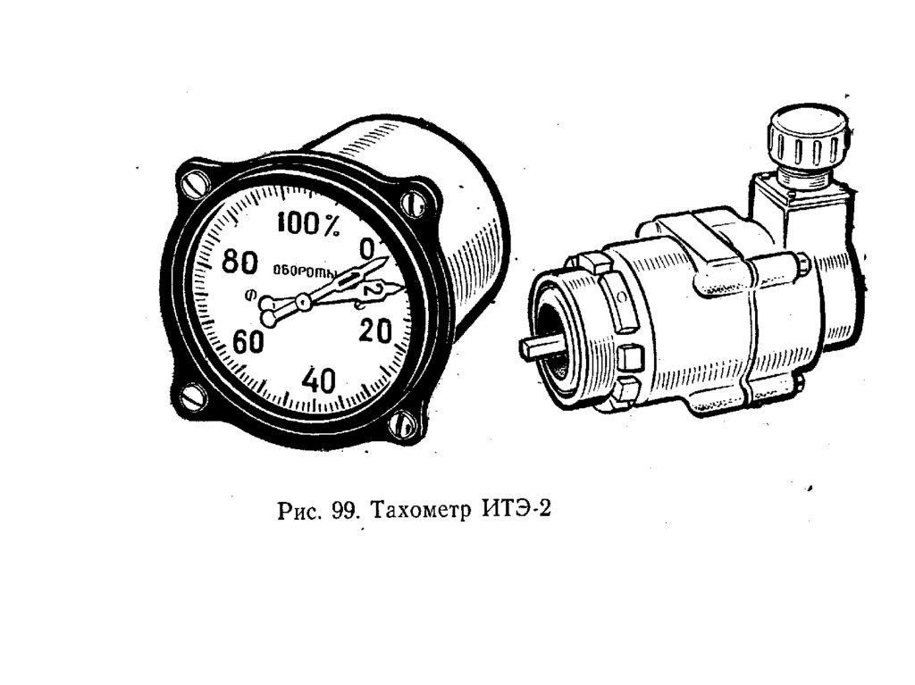
КРД, engine indicating, тахометры
1. КРД ENGINE INDICATING
тахометры2.
3.
4.
5.
6.
7.
8.
Speed Measurement System with a Tacho ProbeRefer to Figure 22.
A speed measuring system incorporating a tacho probe consists of the following
main components:
tacho probe (electromagnetic pick-up) acting as the rpm transmitter
torque synchro inside the rpm indicator
the necessary wiring.
This type of system is used to measure and indicate compressor speeds of an
engine. In some turbo fan engines, the speed of the fan can also be measured.
One advantage of a probe is its ability to provide separate electrical output signals to
other systems (if required). Another advantage is that a probe has no moving parts.
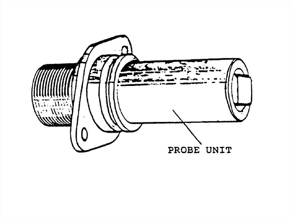
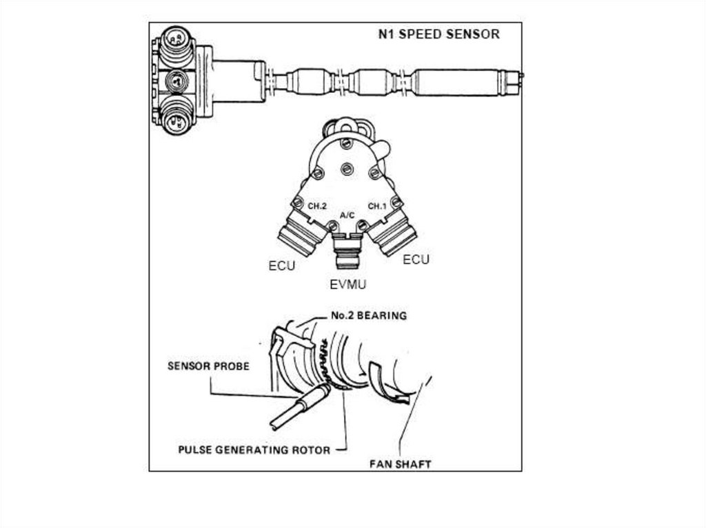
A tacho probe is made of stainless steel and hermetically sealed (airtight seal) to
prevent any foreign matter (dirt, dust) from entering. It consists of a permanent
magnet, a pole piece and a number of coils wound around a central ferromagnetic
core. A flange on the probe allows it to be mounted at that position inside the engine
where the speed measurement is to be made, i.e. where the probe's pole pieces
are close to the teeth of a certain gear wheel. This gear wheel is known as a
'phonic wheel'. It is driven at the same speed as the compressor shaft or fan shaft.
9.
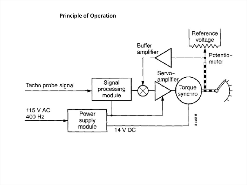
The indicator contains a signal-processing module (servo-amplifier), a motor(torque synchro) and a feedback circuit consisting of a potentiometer and a
buffer amplifier.
Normally, there are 2 spring-loaded pointers which indicate the rpm. A power supply
module provides the necessary AC and DC supplies for the indicator.
10.
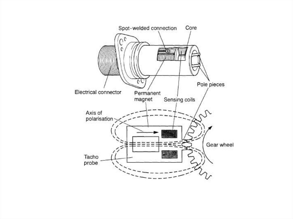
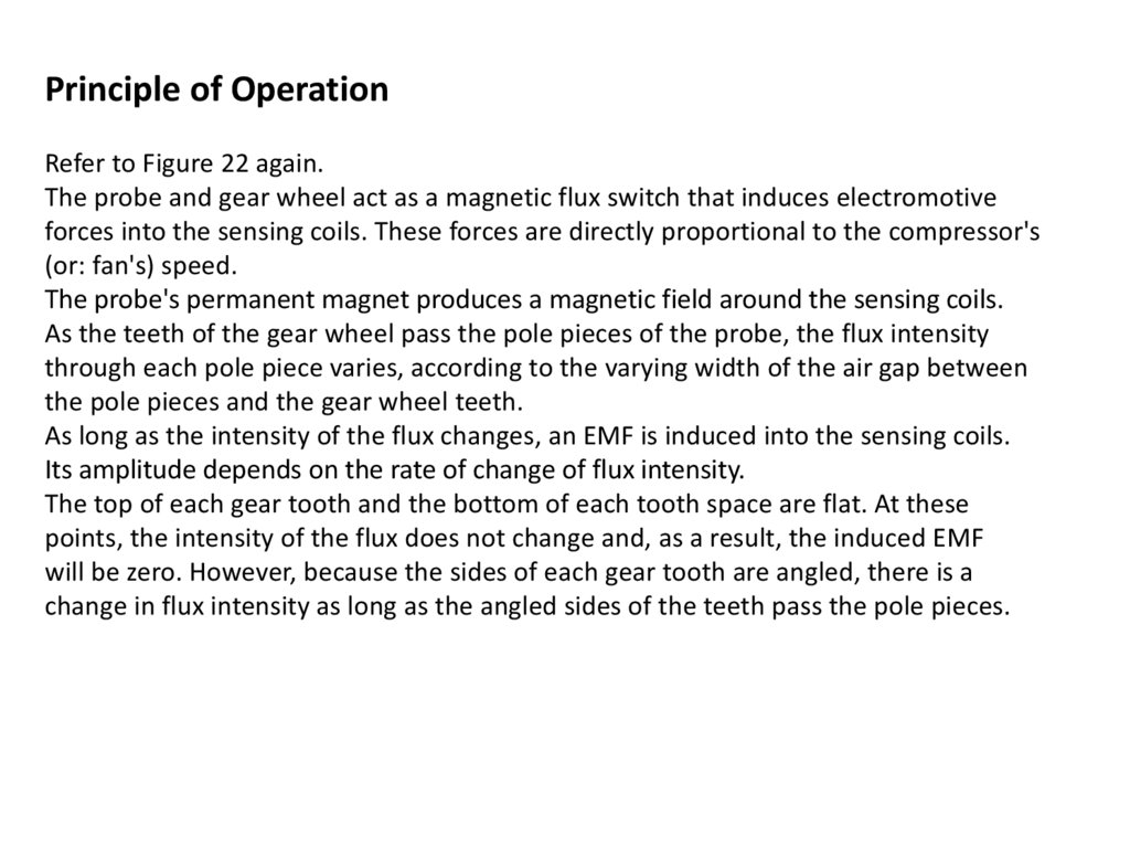
Principle of OperationRefer to Figure 22 again.
The probe and gear wheel act as a magnetic flux switch that induces electromotive
forces into the sensing coils. These forces are directly proportional to the compressor's
(or: fan's) speed.
The probe's permanent magnet produces a magnetic field around the sensing coils.
As the teeth of the gear wheel pass the pole pieces of the probe, the flux intensity
through each pole piece varies, according to the varying width of the air gap between
the pole pieces and the gear wheel teeth.
As long as the intensity of the flux changes, an EMF is induced into the sensing coils.
Its amplitude depends on the rate of change of flux intensity.
The top of each gear tooth and the bottom of each tooth space are flat. At these
points, the intensity of the flux does not change and, as a result, the induced EMF
will be zero. However, because the sides of each gear tooth are angled, there is a
change in flux intensity as long as the angled sides of the teeth pass the pole pieces.
11.
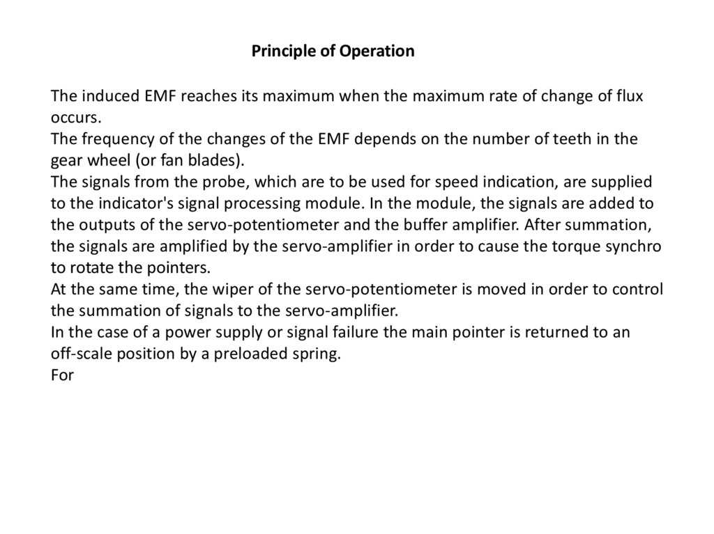
Principle of OperationThe induced EMF reaches its maximum when the maximum rate of change of flux
occurs.
The frequency of the changes of the EMF depends on the number of teeth in the
gear wheel (or fan blades).
The signals from the probe, which are to be used for speed indication, are supplied
to the indicator's signal processing module. In the module, the signals are added to
the outputs of the servo-potentiometer and the buffer amplifier. After summation,
the signals are amplified by the servo-amplifier in order to cause the torque synchro
to rotate the pointers.
At the same time, the wiper of the servo-potentiometer is moved in order to control
the summation of signals to the servo-amplifier.
In the case of a power supply or signal failure the main pointer is returned to an
off-scale position by a preloaded spring.
For
12.
Principle of Operation13. TACHO PROBE SYSTEM INDICATOR
Principle of OperationTACHO PROBE SYSTEM INDICATOR