


 Промышленность
Похожие презентации:


Single screw compressor presentation. Working principle & inspection guidelines
1.
Single screw compressor presentationWorking principle & inspection guidelines
2. Daikin Single G-type Screw Compressor
Internal Use OnlyDaikin Single G-type Screw
Compressor
G - Type Single Screw
R134a
Up to 90 KW120 Hp
R407C
Up to 135KW/180 Hp
22-Apr-20
2
3. Stepless Single Screw Compressor
Internal Use OnlyStepless Single Screw Compressor
History
step control
F-type
step control
G-type
G-type stepless
time
2000
1988
ZH13L & ZH15L
2003
2005
Robustness, reliability = Robustness, reliability
Performance = Performance
Dimensions = Dimensions
Limited control (stepped) ≠Extended control (stepless)
The stepless compressor is a DAIKIN development !
Designed, tested and manufactured in Daikin’s own laboratories.
22-Apr-20
3
4. G type compressor
Internal Use OnlyG type compressor
• Nomenclature
3-5-7-9 sizes
G, G4 = step
GU,G5, G6 =Stepless
22-Apr-20
4
5. G type compressor with step control
Internal Use OnlyG type compressor with step control
G-type step range from 30KW to 135 KW
22-Apr-20
5
6. G type compressor with stepless control
Internal Use OnlyG type compressor with stepless control
G-type stepless range from 30KW to 135 KW
22-Apr-20
6
7. The single, mono or globoïd screw
Internal Use OnlyThe single, mono or globoïd screw
Satelite
Or Gate Rotor =
Special composite
material
driven by 2-pole motor
Open end
Closed end
12 x 2900 = 34,800 compressions per minute = continuous flow !
22-Apr-20
7
8. Gate rotor and gate rotorshaft
Internal Use OnlyGate rotor and gate rotorshaft
22-Apr-20
8
9. The G-type screw compressor
Internal Use OnlyThe G-type screw compressor
Oil separator
& capacitycontrol
22-Apr-20
Compression
section
Motor &
suction section
9
10. The Heart of the single screw compressor
Internal Use OnlyThe Heart of the single screw compressor
Oil separator
& capacitycontrol
22-Apr-20
Compression
section
Motor &
suction section
10
11. The flow inside compressor
Internal Use OnlyThe flow inside compressor
22-Apr-20
11
12.
Internal Use OnlyCompression
Principle
22-Apr-20
12
13. G-type screwcompressor
Internal Use OnlyG-type screwcompressor
• Compression principle
22-Apr-20
13
14. Capacity adjustment design
Internal Use OnlyCapacity adjustment design
Loading & Unloading
Mechanism
G types until 2005
G types from 2005
step control
stepless control
3 to 4 fixed capacity steps
Continuous control
between 30 and 100%
F types
22-Apr-20
14
15. Capacity adjustment design step
Internal Use OnlyCapacity adjustment design step
Step control
Principle
Is based on internal
pressure differences
Selection of capacity
step with solenoid
valves
22-Apr-20
15
16. step control/essential parts
Internal Use Onlystep control/essential parts
• Capacity solenoid valves
12
70%
40%
12%
12
22-Apr-20
16
17. step control/essential parts
Internal Use Onlystep control/essential parts
• Sliding vanes with bridge and springs
22-Apr-20
17
18. step control/essential parts
Internal Use Onlystep control/essential parts
• Slide vane bridge with capacity cylinder/piston
12%
40%
70%
Springs
70
%
22-Apr-20
40
%
12
%
18
19. Capacity adjustment design
Internal Use OnlyCapacity adjustment design
22-Apr-20
19
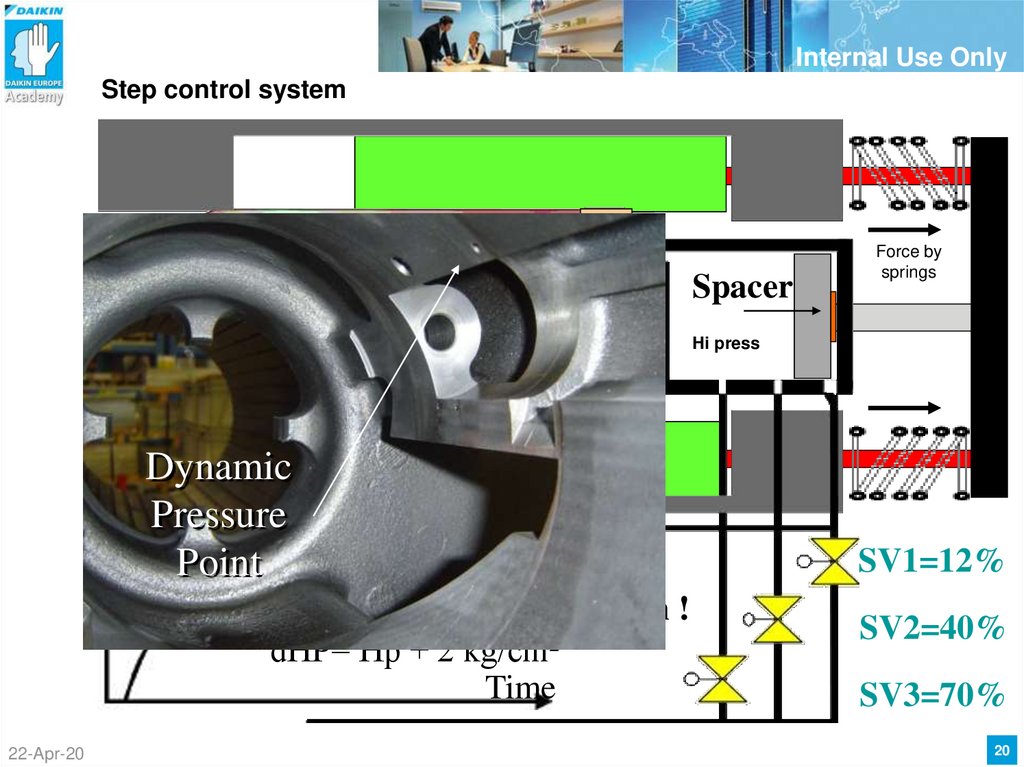
20.
Internal Use OnlyStep control system
Dynamic
pressure
point
Spacer
Force by
springs
Hi press
Screw rotor
Dynamic
Pressure
Pressure
dHp
Point
Hp
Energized = open !
dHP= Hp + 2 kg/cm²
Time
Low pressure side
22-Apr-20
SV1=12%
SV2=40%
SV3=70%
20
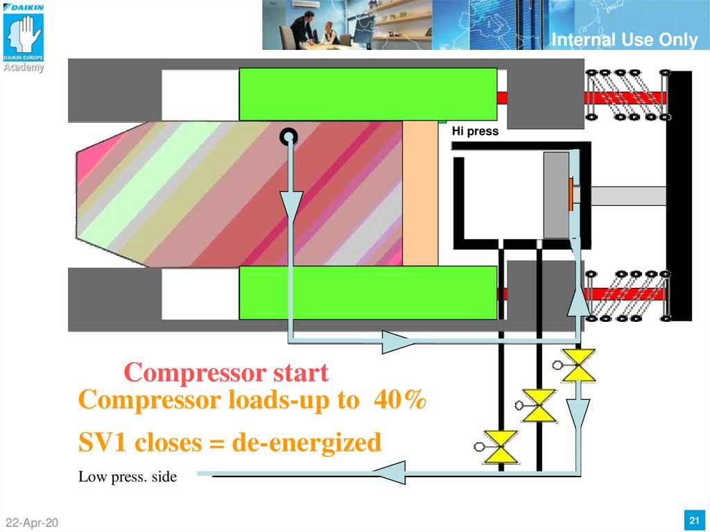
21.
Internal Use OnlyHi press
Compressor start
Compressor loads-up to 40%
SV1 closes = de-energized
Low press. side
22-Apr-20
12%
capacity
21
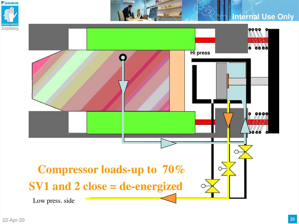
22.
Internal Use OnlyHi press
Compressor loads-up to 70%
SV1 and 2 close = de-energized
Low press. side
22-Apr-20
40%
capacity
22
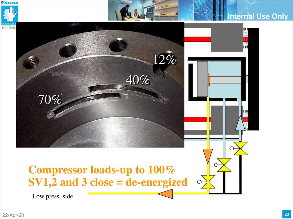
23.
Internal Use Only12%
40%
70%
Compressor loads-up to 100%
SV1,2 and 3 close = de-energized
Low press. side
22-Apr-20
70%
capacity
23
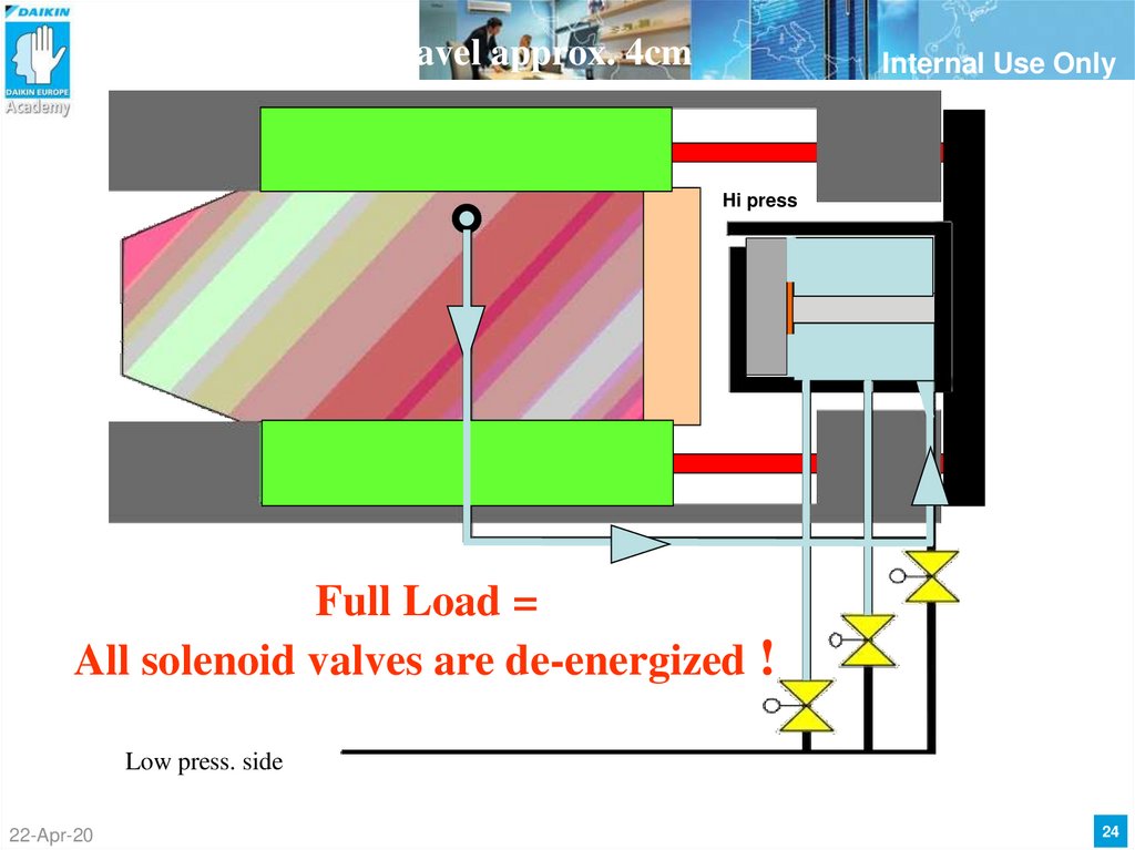
24.
Full travel approx. 4cmInternal Use Only
Hi press
Full Load =
All solenoid valves are de-energized !
Low press. side
22-Apr-20
24
25. Capacity adjustment design stepLESS
Internal Use OnlyCapacity adjustment design stepLESS
Stepless control
Principle
Is based on internal
pressure differences
Regulation of stepless
capacity step with motor
22-Apr-20
25
26. Stepless Single Screw Compressor
Internal Use OnlyStepless Single Screw Compressor
STEPLESS capacity regulation
The compressor has built-in capacity control by 30 – 100%
by stepless slide valve mechanism, and adjustable volumetric ratio
Chiller Load
Chiller Load
100%
100%
30%
Starting position
12%
Demand
Single Circuit
22-Apr-20
15%
12%
Starting position
Demand
Double Circuit
Designed, tested and manufactured in Daikin’s own laboratories.
26
27. G type compressor with stepless control
Internal Use OnlyG type compressor with stepless control
12 % solenoid
Step / motor module
22-Apr-20
27
28. stepless control/essential parts
Internal Use Onlystepless control/essential parts
Slide vanes
Pilot valve/ special piston
22-Apr-20
Slide vanes with bridge
stepmotor
28
29. Stepless Single Screw Compressor
Internal Use OnlyStepless Single Screw Compressor
STEPLESS capacity regulation
How does it work ?
Pilot Valve + cylinder
Loading and unloading via Pilot Valve:
-Pilot valve is driven by rod mechanism
-The rod mechanism is driven by
shaded-pole motor
Loading
Unloading
High pressure side
22-Apr-20
Rod mechanism
29
30. Stepless control
Internal Use OnlyStepless control
STEPLESS capacity regulation
How does it work ?
Pilot Valve
Balancing hole
Bleedhole for pilot valve
High pressure side
Loading
Unloading
22-Apr-20
Rod mechanism
30
31. Stepless regulation/pressure difference
Internal Use OnlyStepless regulation/pressure difference
Sliding Vane
Spring
Load/unload
mechanism
HP (High Pressure)
HP = High pressure =
Pressure of refrigerant at
discharge port
HP
HP dHP
dHp = dynamic high
pressure =
Piston
HP
dHP
Pressure of refrigerant at
just before discharge port =
dHp slightly > HP
Main screw
Dynamic HP
22-Apr-20
HP (High Pressure)
31
32. Stepless Single Screw Compressor
Internal Use OnlyStepless Single Screw Compressor
Sliding Vane
Spring
Gate rotor
HP (High Pressure)
@ 100%
Position of
PILOT VALVE
is not changed!
Load/unload
mechanism
HP
HP dHP
Low Pressure
Small bleed
Towards LPside
(Indicated by the green circle)
Pilot Valve
Low Pressure
HP
dHP
(ΔP = 2kg/cm²)
HP+ spring = dHP
Main screw
Dynamic HP
Bearing of the rotor
22-Apr-20
HP (High Pressure)
Rod mechanism driven
by shaded-pole motor
SLIDING VANE
stays @
position 100%
32
33. Stepless Single Screw Compressor
Internal Use OnlyStepless Single Screw Compressor
Position of
pilot vane
moves to right
side
(towards 90%)
Unloading
from 100% to 90%
@ 100%
Position of
PILOT VALVE
moves right
HP
HP dHP
Low Pressure
Bigger bleed
Towards LPside
HP+spring > dHP
Low Pressure
HP
dHP
SLIDING VANE
moves to right
decrease CC
22-Apr-20
33
34. Stepless Single Screw Compressor
Internal Use OnlyStepless Single Screw Compressor
@ 95%
Position of
PILOT VALVE
moves right
HP
HP dHP
Low Pressure
Bigger bleed
Towards LPside
HP+spring > dHP
Low Pressure
dHP
HP
SLIDING VANE
moves to right
decrease CC
22-Apr-20
34
35. Stepless Single Screw Compressor
Internal Use OnlyStepless Single Screw Compressor
@ 90%
Position of
PILOT VALVE
is not changed!
HP
HP dHP
Low Pressure
Small bleed
Towards LPside
(Indicated by the green circle)
(ΔP = 2kg/cm²)
Low Pressure
dHP
HP
HP+spring =
dHP
SLIDING VANE
stays @
position 90%
22-Apr-20
35
36. Stepless Single Screw Compressor
Internal Use OnlyStepless Single Screw Compressor
Bypass Dyna
Press to Lp
@ start
Y11S – 12%
HP
bleed DP
dHP
HP
Low Pressure
Position of
PILOT VALVE
Completely to
the right!
0% pos
Towards LPside
Via 12% valve
Low Pressure
HP
dHP
No further
cap% build up
possible
SLIDING VANE
stays @
position 12%
22-Apr-20
36
37. Stepless Single Screw Compressor
Internal Use OnlyStepless Single Screw Compressor
• Start up sequence
capacity
100%
30%
Upload
possible
12 %
0%
20 s
40 s
120 s
180 S
Time
Compress
Start
22-Apr-20
37
38. Stepless Single Screw Compressor
Internal Use OnlyStepless Single Screw Compressor
• HPz
Small bleed
dHP
LP
Position of
PILOT VALVE
Does not move
Towards LPside
HP+spring = dHP
Bigger bleed
HP
LP
dHP
Position of
PILOT VALVE
moves RIGHT
Towards LPside
NO bleed
dHP
100%
t0 = t1
15%
Demand
SLIDING VANE moves to right
decreased CC
Chiller Load
100%
t0
15%
Demand
SLIDING VANE moves to left
increased CC
Chiller Load
Position of
PILOT VALVE
moves LEFT
Towards LPside
100%
t1
t0
HP+spring < dHP
22-Apr-20
Chiller Load
t1
HP+spring > dHP
HP
LP
SLIDING VANE does not move
no CC change
15%
Demand
38
39. Stepless Single Screw Compressor
Internal Use OnlyStepless Single Screw Compressor
• Step motor feedback principle
Vcc
Vcc = 21V Single circuit
GND
input
V pot
(double circuit)
Vcc = 12V double circuit
Vpot= Vcc * Rpot
Rpot + R 470
5
white
Red (6) or black (4)
V+
Feedback from potentiometer
R 470
R Pot
Potentiometer Output
@ 100% R=+/- 125 Ohm
@ 30% R=+/- 35 Ohm
22-Apr-20
39
40. Stepless Single Screw Compressor
Internal Use OnlyStepless Single Screw Compressor
• Stepmotor steering for
J4-VG
Analog out 5V
A1P A0
• ZH(A)(C)3,5
J4 Y1
V Comm
TCO1
J4-Y2
Optocouplers
Loadup
TCO1
Loaddown
TCO2
A1
A1
A2
A2
TCO2
GND
Resistance value
towards analog input
ctrl
22-Apr-20
40
41. Stepless Single Screw Compressor
Internal Use OnlyStepless Single Screw Compressor
• Stepmotor steering for
J4-VG
Analog out 5V
A1P A0
• ZH(A)(C)7,9
J4 Y1
V Comm
TCO1
J4-Y2
Optocouplers
Loadup
TCO1
Loaddown
TCO2
A1
A1
A2
A2
TCO2
GND
Resistance value
towards analog input
ctrl
22-Apr-20
41
42. Stepless Single Screw Compressor
Internal Use OnlyStepless Single Screw Compressor
• Stepmotorconnections
ZH.. 3& 5 types
VM30APTE
ZH.. 7&9 types
VM30APZTE
Motor connection
On terminals 2-3
To be switched
GND
GND
230V from SSR’s
230V from SSR’s
Towards anaog
input controller
22-Apr-20
Towards analog
input controller
42
43. Single screw compressor
Internal Use OnlySingle screw compressor
Oil and Liquid injection design
Simplified
Reduces
Lubricates
Cools
Seals
oil sound
management
22-Apr-20
43
44. Single screw compressor
Internal Use OnlySingle screw compressor
• Liquid injection point (fixed oriffice)
Cool Main screw
• Never shut off,
during operation
compressor
• For pumpdown use
integrated pump
down function of
controller
22-Apr-20
44
45. Single screw compressor
Internal Use OnlySingle screw compressor
• Liquid injection piping
(example for EWAD MBY)
22-Apr-20
45
46. Single screw compressor
Internal Use OnlySingle screw compressor
Periodic Inspection
22-Apr-20
46
47. Single screw compressor - Inspection
Internal Use OnlySingle screw compressor - Inspection
Periodic Inspection - Check points
Insulation Resistance of the Motor.
Inspection/Changement of the Refrigerant Oil.
Inspection the Gate Rotor.
Cleaning the Suction filter.
22-Apr-20
47
48. Single screw compressor - Inspection
Internal Use OnlySingle screw compressor - Inspection
Check points
Insulation Resistance of the Motor.
After 1year of operation.
Use a 500-V megger.
Loose all the wires.
Measure between the phases
Measure between the CTP and phases
Measure between earth, CTP and phases
Value >= 3MΩ
22-Apr-20
48
49. Single screw compressor - Inspection
Internal Use OnlySingle screw compressor - Inspection
Check points
Inspection/Changement of the Refrigerant Oil.
Take a oil sample on one of the two oil drain ports.
Check oil (color, acid test, moisture, …)
Reduce the pressure (pump down).
Recover the internal rest pressure.
Take a oil sample on one of the two oil drain ports.
Check oil (color, acid test, moisture, …)
After 7500 hr or 4 years operation. Adviced to change oil
22-Apr-20
49
50. Single screw compressor - Inspection
Internal Use OnlySingle screw compressor - Inspection
• Oil drain ports
22-Apr-20
50
51. Single screw compressor - Inspection
Internal Use OnlySingle screw compressor - Inspection
• Oil charging port & service port (vacuum pump)
Service port
22-Apr-20
51
52. Single screw compressor - Inspection
Internal Use OnlySingle screw compressor - Inspection
Surface
yellowing
Check points
Inspection the Gate Rotor
After 20000 hr or 4 years operation.
scar
Reduce the pressure (pump down).
Recover the internal rest pressure.
Remove the side covers.
Inspection of the gate rotor.
Item
Standard
Cracking
No cracking
Chipping
No chipping 3 mm or
more in long side
Scar
Remedy
Replace
No scar 1 mm or deeper
Surface scratching
22-Apr-20
52
53. Single screw compressor - Inspection
Internal Use OnlySingle screw compressor - Inspection
Check points
Inspection the Gate Rotor
Measuring the slit clearance (60 to 90 μm).
22-Apr-20
53
54. Single screw compressor - Inspection
Internal Use OnlySingle screw compressor - Inspection
Check points
Cleaning the Suction Filter
After 20000 hr or 4 years operation.
Reduce the pressure (pump down).
Recover the internal rest pressure.
Disconnect the suction pipe.
Clean the suction filter with compressed air.
22-Apr-20
54
55. Single screw compressor
Internal Use OnlySingle screw compressor
Overhaul
22-Apr-20
55
56. Low Maintenance Costs
Internal Use OnlyLow Maintenance Costs
Only three rotating parts ...
22-Apr-20
56
57. Low Maintenance Costs
Internal Use OnlyLow Maintenance Costs … and two sliding parts
NO O-rings
NO gaskets
Sealing via
oilpressure
NO Oilpump
22-Apr-20
Oilcirculation
due to differntial
pressure
57
58. Single Screw Compressor - Overhaul
Internal Use OnlySingle Screw Compressor - Overhaul
Overhaul
(see service manual Si50-402A)
• Overhaul interval:40.000 hrs or 7 years, wichever comes first
• Change of oil
• Change of gate rotors if needed + O-rings
• Change of all gaskets and O-rings
• Change of all bearings (mainscrew and gaterotor bearings
Complete dismanteling of compressor needed
22-Apr-20
58
59. Single Screw Compressor - Overhaul
Internal Use OnlySingle Screw Compressor - Overhaul
Overhaul Instructions Chart (See Service Manual SiE50-402A)
1. Disassembly and Inspection
22-Apr-20
Drain The Oil
Remove Side Covers
Inspection of The Gate Rotors and Surrounding Parts
Dissamble The Gate Rotor and Surrounding Parts
Remove and Install The Gate Rotor
Remove The Suction End Cover
Remove The Motor Rotor
Disassemble The Loading/Unloading Mechanism
Remove and Disassemble The Screw Assembly Pulley
59
60. Single Screw Compressor - Overhaul
Internal Use OnlySingle Screw Compressor - Overhaul
Overhaul Instructions Chart(See Service Manual SiE50-402A)
2. Replacing The Bearing
Remove The Bearings
Suction end cover bearing (Outer ring)
Screw shaft bearing (Inner ring)
Main bearing (matched pair)
Gate rotor bearings ( 4 )
Install The Bearings
22-Apr-20
60
61. Single Screw Compressor - Overhaul
Internal Use OnlySingle Screw Compressor - Overhaul
Overhaul Instructions Chart (See Service Manual SiE50-402A)
3. Final Assembly
Assemble The Screw Shaft and Main Bearing Holder
Insert The Screw Shaft
Install The Motor Rotor
Install The Suction End Cover
Verify The Position of The Screw Rotor
Install The Gate Rotor and Adjust The Slit Clearance
Install The Main Bearing Holder Fixing Plate, Assemble The Loading/Unloading
Mechanism and Instal The Oil Filter
Install The Discharge End Cover
22-Apr-20
61
62. Single Screw Compressor - Overhaul
Internal Use OnlySingle Screw Compressor - Overhaul
Overhaul Instructions Chart
(See Service Manual SiE50-402a)
4. Airtightness Test
Using dry air mixed with refrigerant, or Nitrogen, pressurize to A
22-Apr-20
62
63. Single Screw Compressor - Overhaul
Internal Use OnlySingle Screw Compressor - Overhaul
Overhaul Instructions Chart
(See Service Manual SiE50-402a)
5. Charging Oil
Charge the same quantity of oil removed during disassembly
Devide the quantity over the suction and discharge side
22-Apr-20
63
64. Single Screw Compressor - Overhaul
Internal Use OnlySingle Screw Compressor - Overhaul
Overhaul Instructions Chart (See Service Manual SiE50-402a)
6. Caution in Test Operation
Check the tightness of all bolts
Check wiring connection
Check pressures
Check noise and vibrations
22-Apr-20
64
65. Single Screw Compressor – Overhaul pics
Internal Use OnlySingle Screw Compressor – Overhaul pics
22-Apr-20
65
66. Stepless Single Screw Compressor
Internal Use OnlyStepless Single Screw Compressor
• 12 % solenoid valve
22-Apr-20
66