

- ВКонтакте
- РћРТвЂВВВВВВВВнокласснРСвЂВВВВВВВВРєРСвЂВВВВВВВВ
- РњРѕР№ Р В Р’В Р РЋРЎв„ўР В Р’В Р РЋРІР‚ВВВВВВВВРЎР‚
- Telegram
- Blogger
Категория:  Строительство
Строительство
Похожие презентации:


Cost advantages of Buckling Restrained Braced Frame buildings
1.
2010Cost advantages of
Buckling Restrained Braced Frame buildings
in accordance with Eurocode
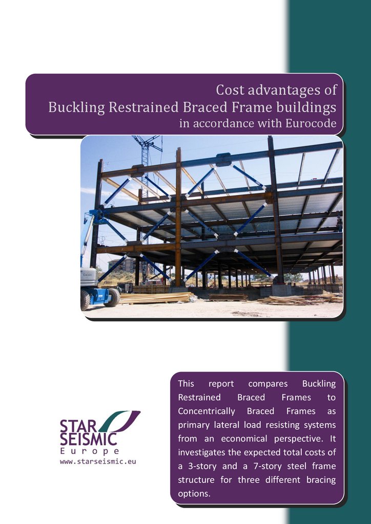
This report compares Buckling
Restrained
Braced
Frames
to
Concentrically Braced Frames as
primary lateral load resisting systems
from an economical perspective. It
investigates the expected total costs of
a 3-story and a 7-story steel frame
structure for three different bracing
options.
2.
INTRODUCTIONThe presented study investigates anticipated cost advantages of Buckling Restrained Braced
Frame (BRBF) systems compared to Concentrically Braced Frame (CBF, Frame with
concentric bracings) systems. The former is a braced frame containing special diagonal
members called Buckling Restrained Braces, characterized by balanced, highly ductile
behavior. The latter is a conventional vertical truss system which is designed so that yielding
of the braces in tension will take place before yielding or buckling of the non-ductile beams
or columns or before failure of the connections. Two types of CBF systems are investigated:
a low dissipative CBF with very limited ductility and a moderately ductile CBF with dissipative
X bracing. Design seismic forces are affected by the level of ductility expected from each
solution, thus buildings with BRBF systems have significantly lower design earthquake loads
than their CBF equipped counterparts.
BRB IN EUROCODES
Unfortunately design regulations for BRBF systems are not yet included in the Eurocodes,
therefore there is no corresponding behavior-factor defined for linear static analysis.
However, as per Eurocode 8 Part 1, Section 4.3.3.4.2.1 seismic no-collapse requirement
check by non-linear static (pushover) or non-linear dynamic (time history, response history)
analysis is an alternative to linear static design. Thus the performance of BRBF equipped
structures can and shall be verified using one of these non-linear techniques. Since the EN
15129 European Standard on Anti-seismic devices includes BRBF among displacement
dependent devices, it is presumable that Eurocode 8 is going to contain details of BRBF
design after its next revision in the near future.
AIM OF COST STUDY
The objective of this study is to show that in spite of being more expensive as a brace
element, using BRBF in moderate or high earthquake prone regions leads to significant
reduction in total structural cost by decreasing the required capacity of every non-dissipative
structural member. The aforementioned three types of bracing solutions are compared in
two structures with different heights in order to show how the savings scale as the number
of stories increases.
STAR SEISMIC EUROPE LTD.
As earthquake awareness among engineers is enhanced by the European standards even in
regions of moderate seismicity, the significance of economical solutions providing adequate
resistance for structures is also increasing. Considering the European trends in the need of
not only well-performing but also economical structural systems has led Star Seismic™ to
focus its operations after North and South America to Europe as well. Star Seismic Europe™
has been set up to professionally serve the increasing European inquiries, providing a new,
more cost-effective anti-seismic structural system in the European market. Star Seismic™
Buckling Restrained Braces can be applied both in new constructions and in seismic retrofit
projects, and can be used in not only in steel, but also in reinforced concrete structures. Star
Seismic Europe™ applies the proven technology of Star Seismic™ who has gained exhaustive
experience over the fabrication of thousands of Buckling Restrained Braces.
1
3.
ASSUMPTIONS AND DESIGN CRITERIAThe buildings modeled in this study are regular, steel frame structures with light weight
decks. Their lateral force resisting bracings are located at the perimeter walls. Following are
the key characteristics of the model:
Standard:
Eurocode (EC) 0, EC 1-1, EC 2-1, EC 3-1, EC 7-1, EC 8-1, EC 8-5
Peak ground acceleration:
0.25 g
Soil type:
C
Importance class and factor: II, γI = 1.0
Analysis procedure:
Equivalent Lateral Force Method
Response spectrum:
type I elastic spectrum
Structural model:
3D
Dead load:
floors:
roof:
4.15 kN/m2
3.25 kN/m2
Live load:
floors:
roof:
3 kN/m2
1 kN/m2
Wind load:
negligible in current calculation
Snow load:
negligible in current calculation
Behavior factor:
CBF:
Star Seismic™ BRBF:
Foundation - piles:
q=1.5 (limited ductility)
q=4.0 (moderate ductility)
q=7.0 (high ductility)
100 cm and 120 cm in diameter
8 m to 18 m in length
piles are designed for both tension and compression
2
4.
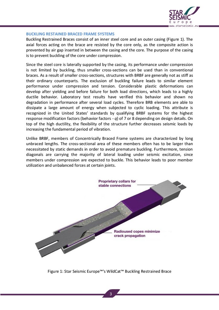
BUCKLING RESTAINED BRACED FRAME SYSTEMSBuckling Restrained Braces consist of an inner steel core and an outer casing (Figure 1). The
axial forces acting on the brace are resisted by the core only, as the composite action is
prevented by air gap inserted in between the casing and the core. The purpose of the casing
is to prevent buckling of the core under compression.
Since the steel core is laterally supported by the casing, its performance under compression
is not limited by buckling, thus smaller cross-sections can be used than in conventional
braces. As a result of smaller cross-sections, structures with BRBF are generally not as stiff as
their ordinary counterparts. The exclusion of buckling failure leads to similar element
performance under compression and tension. Considerable plastic deformations can
develop after yielding and before failure for both load directions, which leads to a highly
ductile behavior. Laboratory test results have verified this behavior and shown no
degradation in performance after several load cycles. Therefore BRB elements are able to
dissipate a large amount of energy when subjected to cyclic loading. This attribute is
recognized in the United States’ standards by qualifying BRBF systems for the highest
response modification factors (behavior factors - q) of 7 or 8 depending on design details. On
top of the high ductility, the flexibility of the structure further decreases seismic loads by
increasing the fundamental period of vibration.
Unlike BRBF, members of Concentrically Braced Frame systems are characterized by long
unbraced lengths. The cross-sectional area of these members often has to be larger than
necessitated by static demands in order to avoid premature buckling. Furthermore, tension
diagonals are carrying the majority of lateral loading under seismic excitation, since
members under compression are expected to buckle. This behavior leads to poor member
utilization and unbalanced forces at certain joints.
Figure 1: Star Seismic Europe™'s WildCat™ Buckling Restrained Brace
3
5.
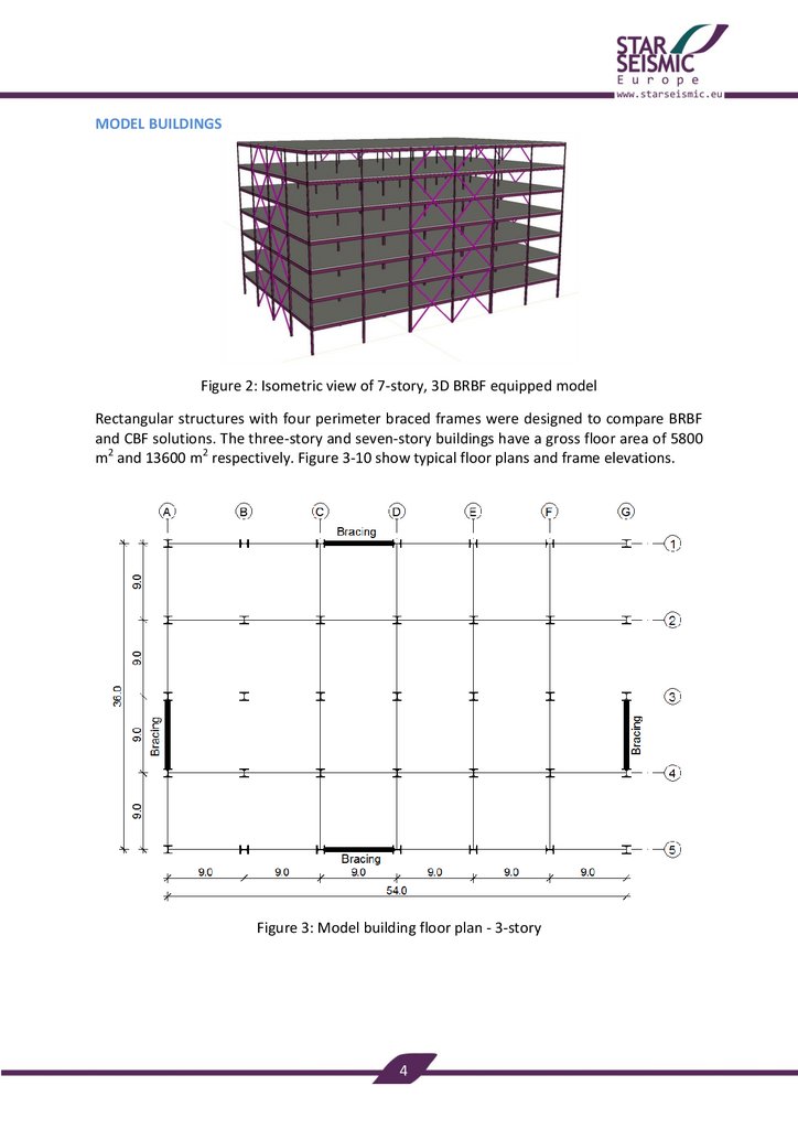
MODEL BUILDINGSFigure 2: Isometric view of 7-story, 3D BRBF equipped model
Rectangular structures with four perimeter braced frames were designed to compare BRBF
and CBF solutions. The three-story and seven-story buildings have a gross floor area of 5800
m2 and 13600 m2 respectively. Figure 3-10 show typical floor plans and frame elevations.
Figure 3: Model building floor plan - 3-story
4
6.
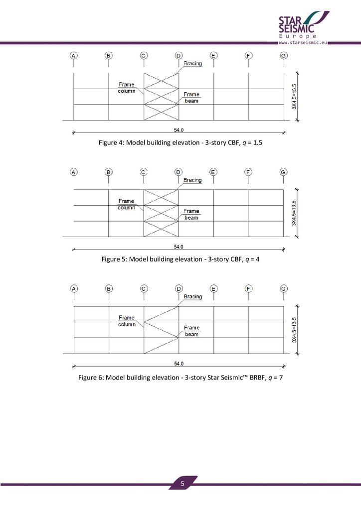
Figure 4: Model building elevation - 3-story CBF, q = 1.5Figure 5: Model building elevation - 3-story CBF, q = 4
Figure 6: Model building elevation - 3-story Star Seismic™ BRBF, q = 7
5
7.
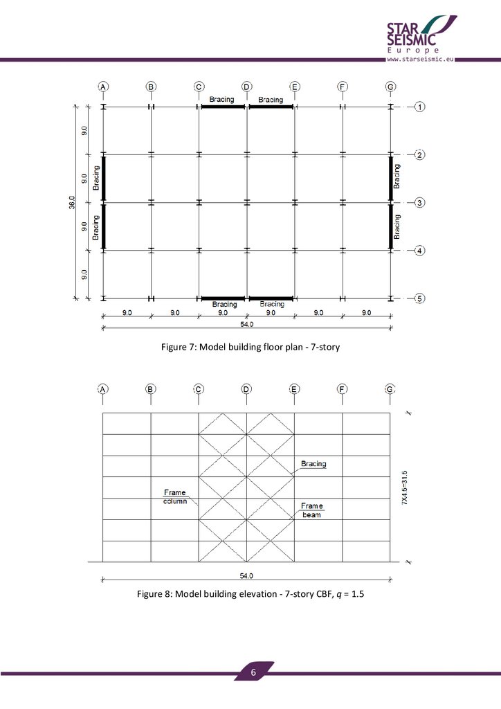
Figure 7: Model building floor plan - 7-storyFigure 8: Model building elevation - 7-story CBF, q = 1.5
6
8.
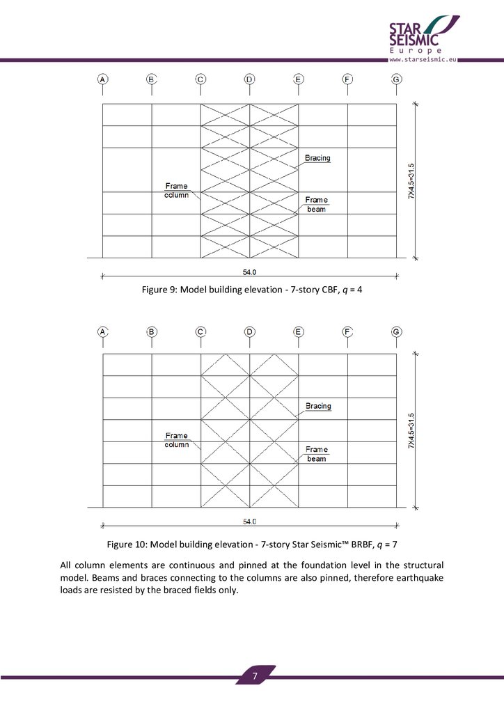
Figure 9: Model building elevation - 7-story CBF, q = 4Figure 10: Model building elevation - 7-story Star Seismic™ BRBF, q = 7
All column elements are continuous and pinned at the foundation level in the structural
model. Beams and braces connecting to the columns are also pinned, therefore earthquake
loads are resisted by the braced fields only.
7
9.
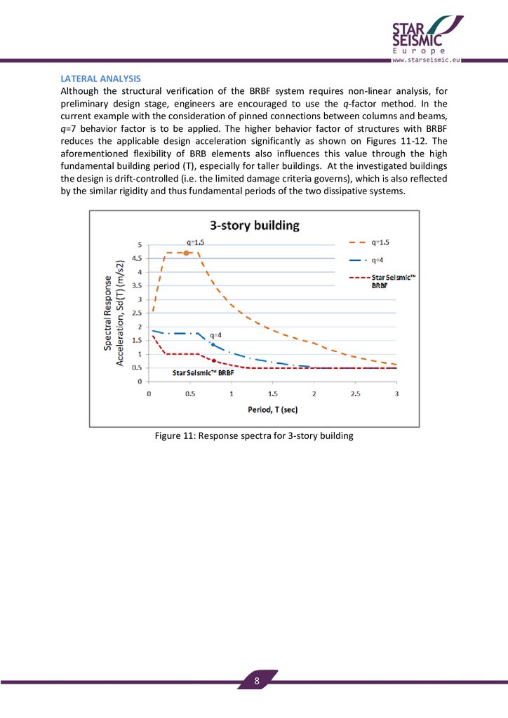
LATERAL ANALYSISAlthough the structural verification of the BRBF system requires non-linear analysis, for
preliminary design stage, engineers are encouraged to use the q-factor method. In the
current example with the consideration of pinned connections between columns and beams,
q=7 behavior factor is to be applied. The higher behavior factor of structures with BRBF
reduces the applicable design acceleration significantly as shown on Figures 11-12. The
aforementioned flexibility of BRB elements also influences this value through the high
fundamental building period (T), especially for taller buildings. At the investigated buildings
the design is drift-controlled (i.e. the limited damage criteria governs), which is also reflected
by the similar rigidity and thus fundamental periods of the two dissipative systems.
Figure 11: Response spectra for 3-story building
8
10.
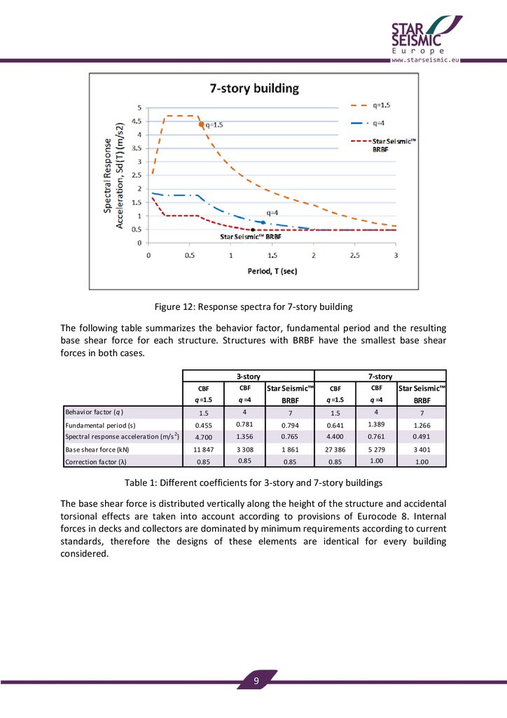
Figure 12: Response spectra for 7-story buildingThe following table summarizes the behavior factor, fundamental period and the resulting
base shear force for each structure. Structures with BRBF have the smallest base shear
forces in both cases.
3-story
CBF
CBF
q =4
q =1.5
q =4
Star Seismic™
BRBF
1.5
4
7
1.5
4
7
Fundamental period (s)
0.455
0.781
0.794
0.641
1.389
1.266
Spectral response acceleration (m/s 2 )
4.700
1.356
0.765
4.400
0.761
0.491
11 847
3 308
1 861
27 386
5 279
3 401
0.85
0.85
0.85
1.00
1.00
Base shear force (kN)
Correction factor (λ)
CBF
q =1.5
7-story
Star Seismic™
BRBF
Behavior factor (q )
CBF
0.85
Table 1: Different coefficients for 3-story and 7-story buildings
The base shear force is distributed vertically along the height of the structure and accidental
torsional effects are taken into account according to provisions of Eurocode 8. Internal
forces in decks and collectors are dominated by minimum requirements according to current
standards, therefore the designs of these elements are identical for every building
considered.
9
11.
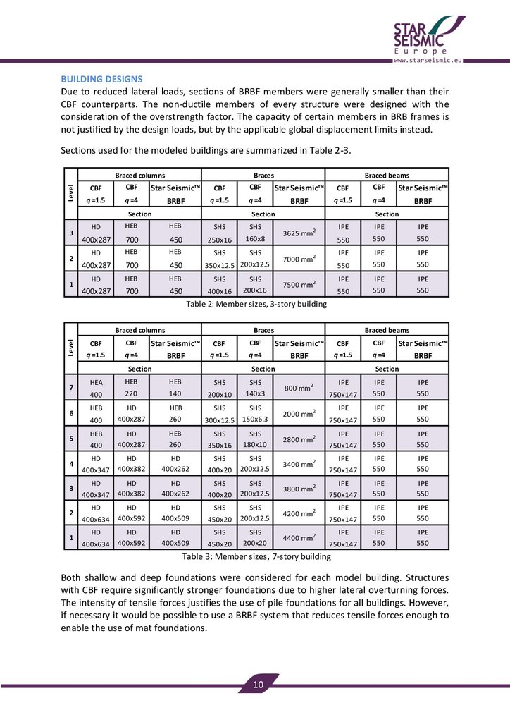
BUILDING DESIGNSDue to reduced lateral loads, sections of BRBF members were generally smaller than their
CBF counterparts. The non-ductile members of every structure were designed with the
consideration of the overstrength factor. The capacity of certain members in BRB frames is
not justified by the design loads, but by the applicable global displacement limits instead.
Sections used for the modeled buildings are summarized in Table 2-3.
Level
Braced columns
CBF
CBF
q =1.5
q =4
HD
HEB
400x287
HD
Braces
CBF
CBF
q =1.5
q =4
HEB
SHS
SHS
700
450
250x16
160x8
HEB
HEB
SHS
SHS
Star Seismic™
BRBF
Section
3
2
1
Braced beams
Star Seismic™
BRBF
CBF
CBF
q =1.5
q =4
IPE
IPE
IPE
550
550
550
Section
400x287
700
450
HD
HEB
HEB
SHS
400x287
700
450
400x16
Section
3625 mm2
7000 mm2
350x12.5 200x12.5
SHS
200x16
Star Seismic™
BRBF
7500 mm2
IPE
IPE
IPE
550
550
550
IPE
IPE
550
IPE
550
550
Table 2: Member sizes, 3-story building
Level
Braced columns
CBF
Braces
Star Seismic™
BRBF
CBF
q =1.5
CBF
q =1.5
q =4
HEA
HEB
HEB
SHS
400
220
140
200x10
HEB
HD
400x287
HEB
260
SHS
300x12.5
HD
400x287
HEB
260
350x16
HD
400x382
HD
400x262
400x20
HD
400x382
HD
400x262
400x20
HD
400x592
HD
400x509
HD
400x592
HD
400x509
Section
7
6
5
4
3
2
1
400
HEB
400
HD
400x347
HD
400x347
HD
400x634
HD
400x634
CBF
q =4
Braced beams
Star Seismic™
BRBF
CBF
q =1.5
Section
SHS
SHS
SHS
SHS
450x20
SHS
450x20
CBF
q =4
Star Seismic™
BRBF
Section
SHS
140x3
800 mm2
SHS
150x6.3
2000 mm2
SHS
180x10
2800 mm2
SHS
200x12.5
3400 mm2
SHS
200x12.5
3800 mm2
SHS
200x12.5
4200 mm2
SHS
200x20
4400 mm2
IPE
750x147
IPE
750x147
IPE
750x147
IPE
750x147
IPE
750x147
IPE
750x147
IPE
750x147
IPE
550
IPE
550
IPE
550
IPE
550
IPE
550
IPE
550
IPE
550
IPE
550
IPE
550
IPE
550
IPE
550
IPE
550
IPE
550
IPE
550
Table 3: Member sizes, 7-story building
Both shallow and deep foundations were considered for each model building. Structures
with CBF require significantly stronger foundations due to higher lateral overturning forces.
The intensity of tensile forces justifies the use of pile foundations for all buildings. However,
if necessary it would be possible to use a BRBF system that reduces tensile forces enough to
enable the use of mat foundations.
10
12.
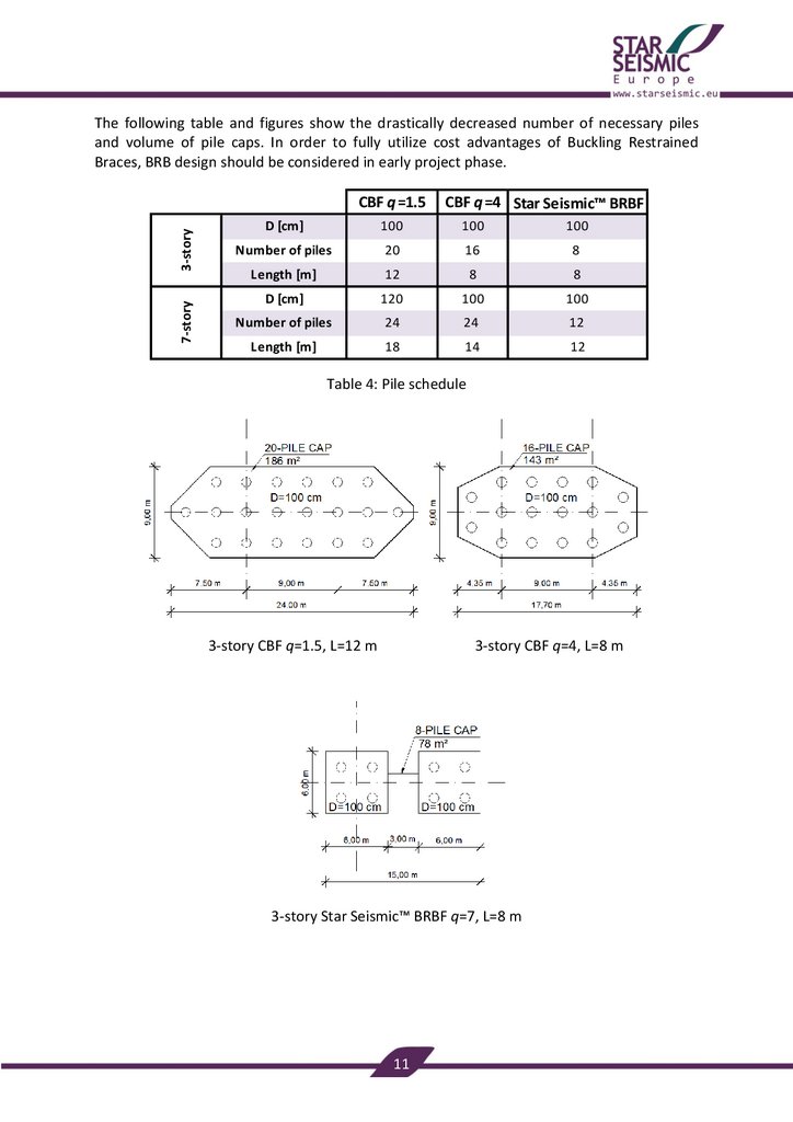
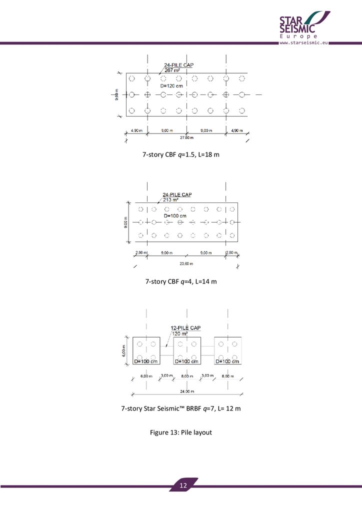
The following table and figures show the drastically decreased number of necessary pilesand volume of pile caps. In order to fully utilize cost advantages of Buckling Restrained
Braces, BRB design should be considered in early project phase.
7-story
3-story
CBF q =1.5
CBF q =4 Star Seismic™ BRBF
D [cm]
100
100
100
Number of piles
20
16
8
Length [m]
12
8
8
D [cm]
120
100
100
Number of piles
24
24
12
Length [m]
18
14
12
Table 4: Pile schedule
3-story CBF q=1.5, L=12 m
3-story CBF q=4, L=8 m
3-story Star Seismic™ BRBF q=7, L=8 m
11
13.
7-story CBF q=1.5, L=18 m7-story CBF q=4, L=14 m
7-story Star Seismic™ BRBF q=7, L= 12 m
Figure 13: Pile layout
12
14.
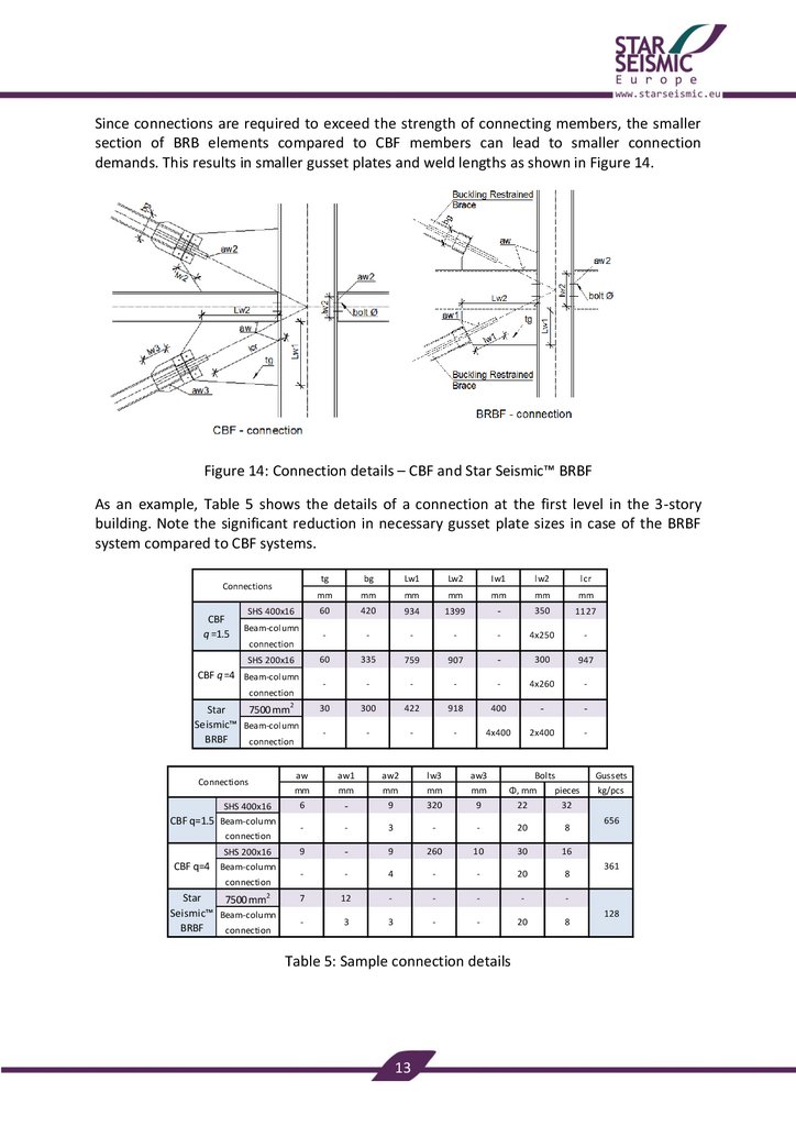
Since connections are required to exceed the strength of connecting members, the smallersection of BRB elements compared to CBF members can lead to smaller connection
demands. This results in smaller gusset plates and weld lengths as shown in Figure 14.
Figure 14: Connection details – CBF and Star Seismic™ BRBF
As an example, Table 5 shows the details of a connection at the first level in the 3-story
building. Note the significant reduction in necessary gusset plate sizes in case of the BRBF
system compared to CBF systems.
Connections
CBF
q =1.5
SHS 400x16
Beam-column
connection
SHS 200x16
CBF q =4 Beam-column
connection
Star
7500 mm2
Seismic™ Beam-column
BRBF
connection
Connections
SHS 400x16
CBF q=1.5 Beam-column
connection
SHS 200x16
CBF q=4 Beam-column
connection
Star
7500 mm2
Seismic™ Beam-column
BRBF
connection
tg
bg
Lw1
Lw2
Iw1
lw2
lcr
mm
mm
mm
mm
mm
mm
mm
60
420
934
1399
-
350
1127
-
-
-
-
-
4x250
-
60
335
759
907
-
300
947
-
-
-
-
-
4x260
-
30
300
422
918
400
-
-
-
-
-
-
4x400
2x400
-
aw
aw1
aw2
lw3
aw3
mm
mm
mm
mm
mm
Φ, mm
Bolts
pieces
6
-
9
320
9
22
32
-
-
3
-
-
20
8
9
-
9
260
10
30
16
-
-
4
-
-
20
8
7
12
-
-
-
-
-
-
3
3
-
-
20
8
Table 5: Sample connection details
13
Gussets
kg/pcs
656
361
128
15.
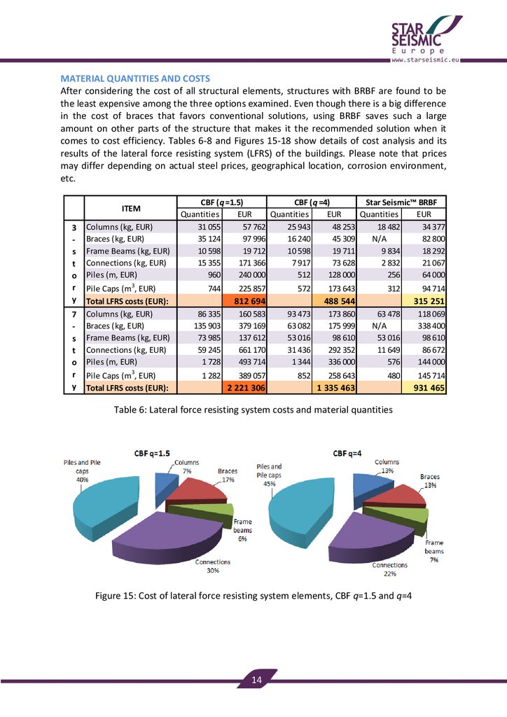
MATERIAL QUANTITIES AND COSTSAfter considering the cost of all structural elements, structures with BRBF are found to be
the least expensive among the three options examined. Even though there is a big difference
in the cost of braces that favors conventional solutions, using BRBF saves such a large
amount on other parts of the structure that makes it the recommended solution when it
comes to cost efficiency. Tables 6-8 and Figures 15-18 show details of cost analysis and its
results of the lateral force resisting system (LFRS) of the buildings. Please note that prices
may differ depending on actual steel prices, geographical location, corrosion environment,
etc.
ITEM
3
s
t
o
r
y
7
s
t
o
r
y
Columns (kg, EUR)
Braces (kg, EUR)
Frame Beams (kg, EUR)
Connections (kg, EUR)
Piles (m, EUR)
Pile Caps (m3, EUR)
Total LFRS costs (EUR):
Columns (kg, EUR)
Braces (kg, EUR)
Frame Beams (kg, EUR)
Connections (kg, EUR)
Piles (m, EUR)
Pile Caps (m3, EUR)
Total LFRS costs (EUR):
CBF (q =1.5)
CBF (q =4)
Star Seismic™ BRBF
Quantities
EUR
Quantities
EUR
Quantities
EUR
31 055
57 762
25 943
48 253
18 482
34 377
35 124
97 996
16 240
45 309
N/A
82 800
10 598
19 712
10 598
19 711
9 834
18 292
15 355
171 366
7 917
73 628
2 832
21 067
960
240 000
512
128 000
256
64 000
744
225 857
572
812 694
86 335
135 903
73 985
59 245
1 728
1 282
312
488 544
160 583
379 169
137 612
661 170
493 714
93 473
63 082
53 016
31 436
1 344
389 057
852
2 221 306
173 643
315 251
173 860
175 999
98 610
292 352
336 000
63 478
N/A
53 016
11 649
576
258 643
480
1 335 463
Table 6: Lateral force resisting system costs and material quantities
Figure 15: Cost of lateral force resisting system elements, CBF q=1.5 and q=4
14
94 714
118 069
338 400
98 610
86 672
144 000
145 714
931 465
16.
According to Table 7 and Figure 16, significant savings can be realized against both CBFequipped structures by the use of BRBF. Not only lighter columns and beams can be used
with the BRBF system due to lower seismic forces, but also significant economic advantage
lies in the cost of connections. Since the stable and highly ductile behavior of the braces
does not require stiffeners installed in gusset plates, light and easy-to-fabricate gussets can
be used saving a considerable amount of material. Most importantly, loads on foundations
are notably smaller with BRBF system, therefore the number and length of piles, volume of
pile caps are drastically reduced.
ITEM
3
s
t
o
r
y
7
s
t
o
r
y
Columns (kg, EUR)
Braces (EUR)
Frame Beams (kg, EUR)
Connections (kg, EUR)
Piles (m, EUR)
Pile Caps (m3, EUR)
Total LFRS savings:
Columns (kg, EUR)
Braces (EUR)
Frame Beams (kg, EUR)
Connections (kg, EUR)
Piles (m, EUR)
Pile Caps (m3, EUR)
Total LFRS savings:
Star Seismic™ BRBF savings
to CBF (q =1.5)
to CBF (q =4)
Quantities
EUR
Quantities
EUR
12 573
23 386
7 461
13 877
N/A
15 196
N/A
-37 491
764
1 420
763
1 419
12 524
150 299
5 085
52 560
704
176 000
256
64 000
432
131 143
260
497 443
78 929
173 294
22 857
N/A
20 969
47 595
1 152
42 514
40 769
39 002
574 498
349 714
29 995
N/A
0
19 786
768
55 791
-162 401
0
205 680
192 000
802
243 343
372
112 929
1 289 841
403 998
Table 7: Material and cost savings of the lateral force resisting system
Figure 16: Cost of elements, Star Seismic™ BRBF compared to CBF q=1.5 and q=4
15
17.
Figure 17: Cost of lateral force resisting system relative to building heightFigure 18: Cost of lateral force resisting system of CBF and Star Seismic™ BRBF buildings
As Figures 17-18 confirm, the amount of savings is proportional to the height of the building.
BRBF is a lateral force resisting system with the lowest system cost and the lowest total
structural cost (including each and every column, beam, brace, connection and foundation of
the building) among the considered solutions. Savings are only realized in the lateral force
resisting system as seismic forces are not the governing actions in the rest of the building.
Needless to say, in case of structures with relatively high ratio of braced bays, such as
technological and industrial structures, total structural cost savings can be almost identical
to savings on the lateral force resisting system.
16
18.
CBF (q =4)EUR/m2
EUR
Star Seismic™ BRBF
EUR/m2
EUR
3-story
CBF (q =1.5)
EUR/m2
EUR
Total structural cost
3 944 694
680
3 620 544
624
3 447 251
594
812 694
140
488 544
84
315 251
54
7-story
ITEM
Total structural cost
9 565 306
703
8 679 463
638
8 275 465
608
LFRS cost
2 221 306
163
1 335 463
98
931 465
68
LFRS cost
Total structural cost savings with Star Seismic™ BRBF system
compared to CBF (q =1.5)
compared to CBF (q =4)
3-story
7-story
86 EUR/m2
95 EUR/m2
30 EUR/m2
30 EUR/m2
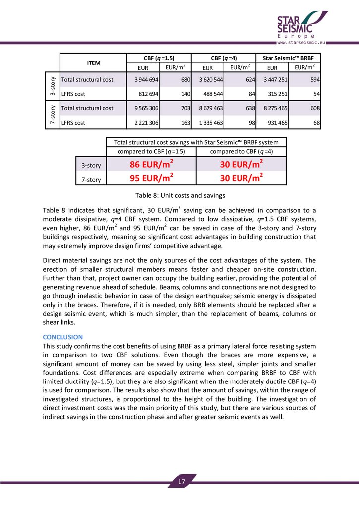
Table 8: Unit costs and savings
Table 8 indicates that significant, 30 EUR/m2 saving can be achieved in comparison to a
moderate dissipative, q=4 CBF system. Compared to low dissipative, q=1.5 CBF systems,
even higher, 86 EUR/m2 and 95 EUR/m2 can be saved in case of the 3-story and 7-story
buildings respectively, meaning so significant cost advantages in building construction that
may extremely improve design firms’ competitive advantage.
Direct material savings are not the only sources of the cost advantages of the system. The
erection of smaller structural members means faster and cheaper on-site construction.
Further than that, project owner can occupy the building earlier, providing the potential of
generating revenue ahead of schedule. Beams, columns and connections are not designed to
go through inelastic behavior in case of the design earthquake; seismic energy is dissipated
only in the braces. Therefore, if it is needed, only BRB elements should be replaced after a
design seismic event, which is much simpler, than the replacement of beams, columns or
shear links.
CONCLUSION
This study confirms the cost benefits of using BRBF as a primary lateral force resisting system
in comparison to two CBF solutions. Even though the braces are more expensive, a
significant amount of money can be saved by using less steel, simpler joints and smaller
foundations. Cost differences are especially extreme when comparing BRBF to CBF with
limited ductility (q=1.5), but they are also significant when the moderately ductile CBF (q=4)
is used for comparison. The results also show that the amount of savings, within the range of
investigated structures, is proportional to the height of the building. The investigation of
direct investment costs was the main priority of this study, but there are various sources of
indirect savings in the construction phase and after greater seismic events as well.
17
19.
REFERENCESDasse Design Inc.: Cost Advantages of Buckling Restrained Braced Frame Buildings,
2009
W. A. López and R. Sabelli: Seismic Design of Buckling-Restrained Braced Frames. Steel
Tips, 2004
CEN: EN 1998, Eurocode 8: Design of structures for earthquake resistance
CEN: EN 15129: Anti-seismic devices
Star Seismic Europe Ltd.: Preliminary design of BRBF system - Use of equivalent lateral
force method, 2009
American Institute of Steel Construction: AISC 341-05: Seismic Provisions for Structural
Steel Buildings, 2005
This study was performed by Star Seismic Europe Ltd. (www.starseismic.eu)
and Civil Engineering Optimal Solutions Ltd. (www.ce-os.eu).
Copyright © 2010, Star Seismic Europe Ltd. All rights reserved. For permission to use
material from this report submit your request to info@starseismic.eu.
18