
 Строительство
Похожие презентации:


")


Buckling-restrained brace
1.
Chapter 1: Composition and history of Buckling‐restrained BracesBUCKLING-RESTRAINED BRACE
HISTORY, DESIGN and APPLICATIONS
Toru Takeuchi, Akira Wada
Ryota Matsui, Ben Sitler, Pao-Chun Lin,
Fatih Sutcu, Hiroyasu Sakata, Zhe Qu
1
1
Buckling‐restrained Braces and Applications
2.
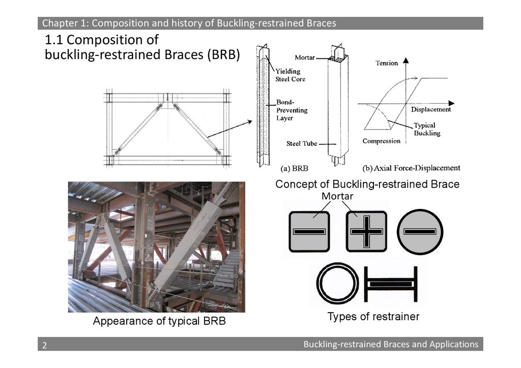
Chapter 1: Composition and history of Buckling‐restrained Braces1.1 Composition of
buckling‐restrained Braces (BRB)
Concept of Buckling-restrained Brace
Mortar
Appearance of typical BRB
2
2
Types of restrainer
Buckling‐restrained Braces and Applications
3.
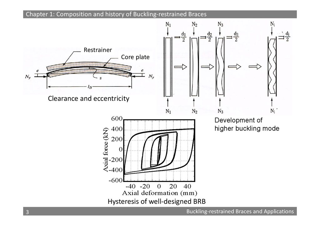
Chapter 1: Composition and history of Buckling‐restrained BracesRestrainer
Core plate
Clearance and eccentricity
Axial force (kN)
600
Development of
higher buckling mode
400
200
0
-200
-400
-600
-40 -20 0 20 40
Axial deformation (mm)
Hysteresis of well‐designed BRB
3
3
Buckling‐restrained Braces and Applications
4.
Chapter 1: Composition and history of Buckling‐restrained Braces1.2 History of Development
1972: Takeda et al. tried to improve the post-buckling behaviour of
H-section braces by encasing the steel section in reinforced
concrete. However, because no debonding mechanism was
provided, the restrainer received a significant compressive
force, cracked and ultimately experienced overall buckling.
1979: Motizuki et al. proposed introducing a debonding layer
between the core plate and reinforced concrete restrainer.
However, the system tended to buckle at the unrestrained core
extension
1988: The first practical buckling-restrained brace was achieved by
Saeki, Wada, et al. employed rectangular steel tubes with infilled mortar for the restrainer, and determined the optimal
debonding material specifications to obtain stable and
symmetric hysteresis behaviour.
4
4
Buckling‐restrained Braces and Applications
5.
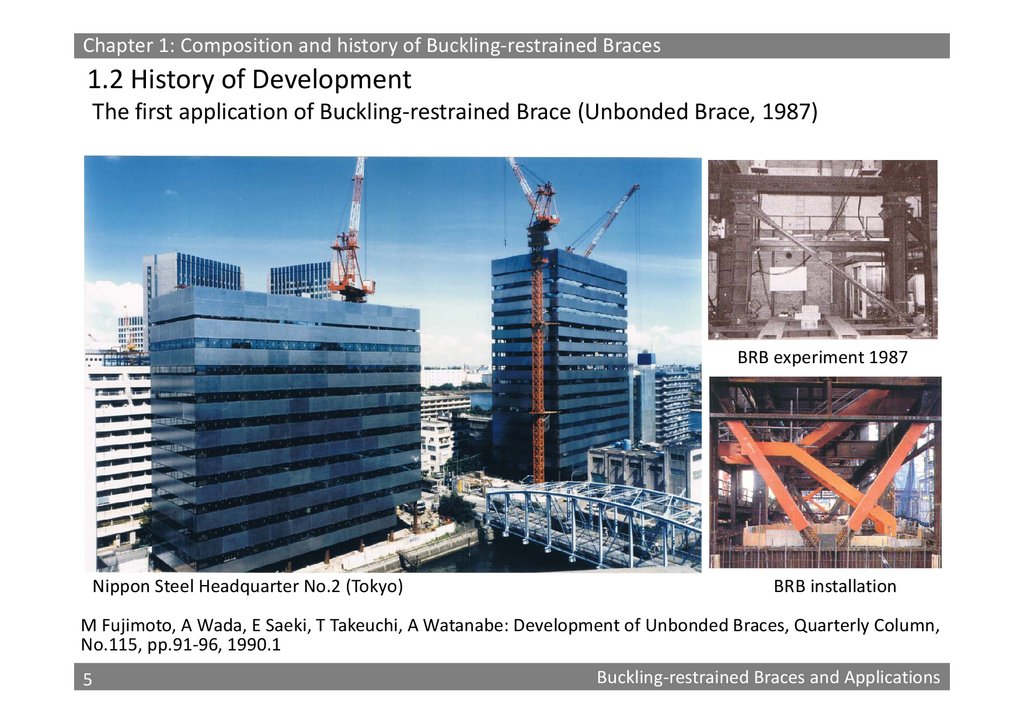
Chapter 1: Composition and history of Buckling‐restrained Braces1.2 History of Development
The first application of Buckling‐restrained Brace (Unbonded Brace, 1987)
BRB experiment 1987
Nippon Steel Headquarter No.2 (Tokyo)
BRB installation
M Fujimoto, A Wada, E Saeki, T Takeuchi, A Watanabe: Development of Unbonded Braces, Quarterly Column,
No.115, pp.91‐96, 1990.1
5
5
Buckling‐restrained Braces and Applications
6.
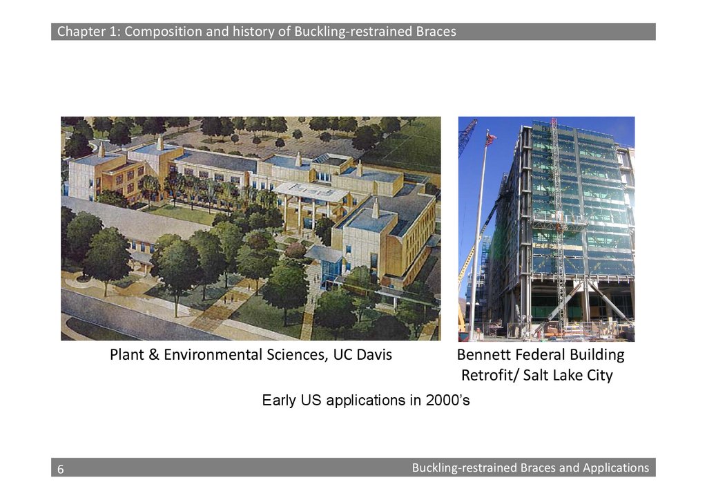
Chapter 1: Composition and history of Buckling‐restrained BracesPlant & Environmental Sciences, UC Davis
Bennett Federal Building
Retrofit/ Salt Lake City
Early US applications in 2000’s
6
6
Buckling‐restrained Braces and Applications
7.
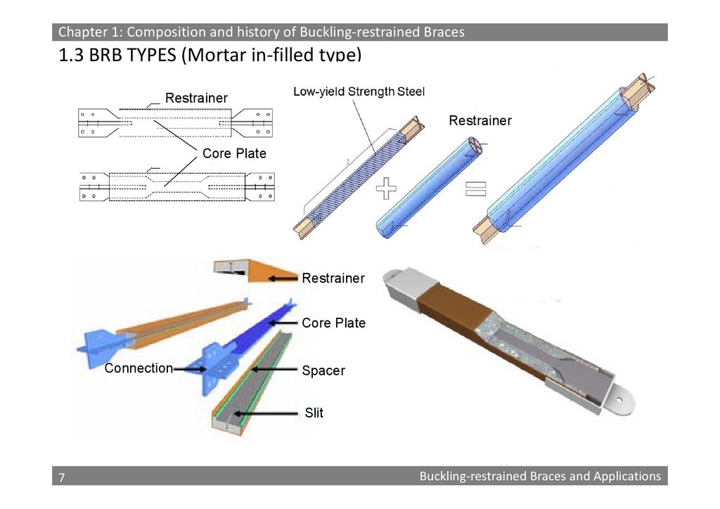
Chapter 1: Composition and history of Buckling‐restrained Braces1.3 BRB TYPES (Mortar in‐filled type)
Restrainer
Restrainer
Core Plate
Restrainer
Core Plate
Connection
Spacer
Slit
7
7
Buckling‐restrained Braces and Applications
8.
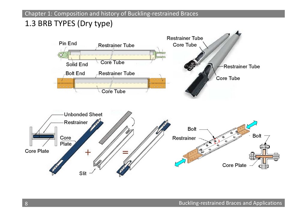
Chapter 1: Composition and history of Buckling‐restrained Braces1.3 BRB TYPES (Dry type)
Pin End
Restrainer Tube
Solid End
Bolt End
Restrainer Tube
Core Tube
Core Tube
Restrainer Tube
Restrainer Tube
Core Tube
Core Tube
Unbonded Sheet
Restrainer
Bolt
Core
Plate
Bolt
Restrainer
Core Plate
Core Plate
Slit
8
8
Buckling‐restrained Braces and Applications
9.
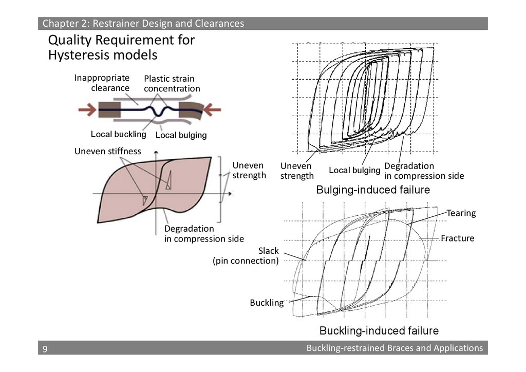
Chapter 2: Restrainer Design and ClearancesQuality Requirement for
Hysteresis models
Inappropriate
clearance
Plastic strain
concentration
Local buckling
Local bulging
Uneven stiffness
Uneven
strength
Uneven
strength
Local bulging Degradation
in compression side
Bulging-induced failure
Tearing
Degradation
in compression side
Fracture
Slack
(pin connection)
Buckling
Buckling-induced failure
9
9
Buckling‐restrained Braces and Applications
10.
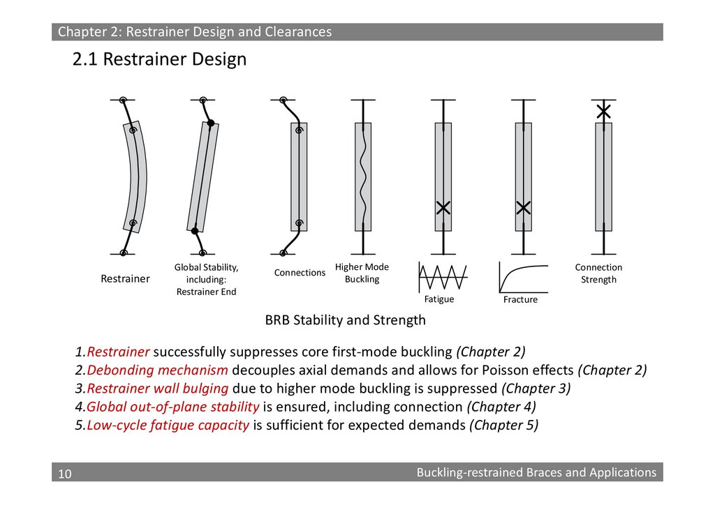
Chapter 2: Restrainer Design and Clearances2.1 Restrainer Design
Restrainer
Global Stability,
including:
Restrainer End
Connections
Higher Mode
Buckling
Connection
Strength
Fatigue
Fracture
BRB Stability and Strength
1.Restrainer successfully suppresses core first‐mode buckling (Chapter 2)
2.Debonding mechanism decouples axial demands and allows for Poisson effects (Chapter 2)
3.Restrainer wall bulging due to higher mode buckling is suppressed (Chapter 3)
4.Global out‐of‐plane stability is ensured, including connection (Chapter 4)
5.Low‐cycle fatigue capacity is sufficient for expected demands (Chapter 5)
10
10
Buckling‐restrained Braces and Applications
11.
Chapter 2: Restrainer Design and ClearancesN crE ac
ac yc E
N cr N cu
N cu a 2s e
N cu ac
B
M N cu (ac yc )
M
y
1 N cu N crB
1 N cu N crB
B
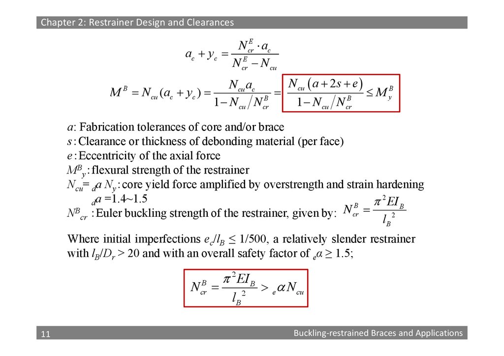
a: Fabrication tolerances of core and/or brace
s Clearance or thickness of debonding material (per face)
e Eccentricity of the axial force
MBy flexural strength of the restrainer
Ncu= da Ny core yield force amplified by overstrength and strain hardening
da =1.4~1.5
2 EI B
B
NBcr Euler buckling strength of the restrainer, given by: N cr
lB 2
Where initial imperfections ec/lB ≤ 1/500, a relatively slender restrainer
with lB/Dr > 20 and with an overall safety factor of eα ≥ 1.5;
N crB
11
11
2 EI B
lB
2
e N cu
Buckling‐restrained Braces and Applications
12.
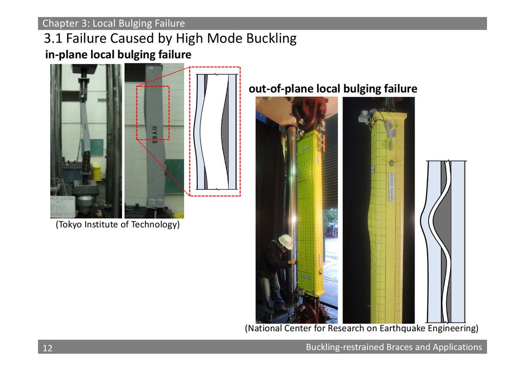
Chapter 3: Local Bulging Failure3.1 Failure Caused by High Mode Buckling
in‐plane local bulging failure
out‐of‐plane local bulging failure
(Tokyo Institute of Technology)
(National Center for Research on Earthquake Engineering)
12
12
Buckling‐restrained Braces and Applications
13.
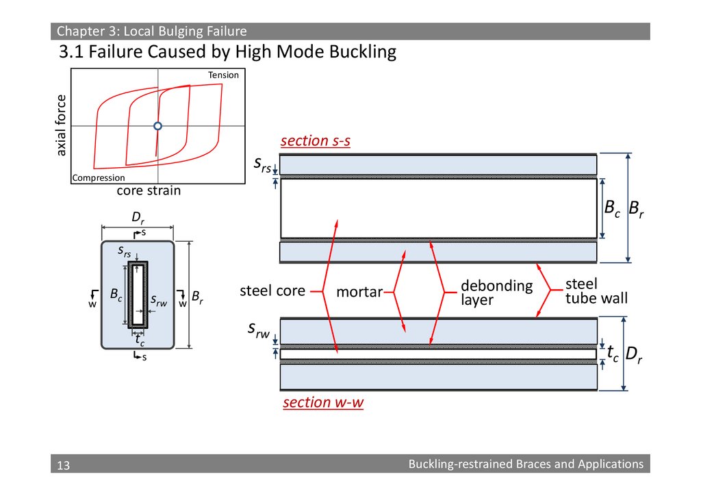
Chapter 3: Local Bulging Failure3.1 Failure Caused by High Mode Buckling
axial force
Tension
section s‐s
srs
Compression
core strain
Bc Br
Bc
Dr
s
srs
w
Bc
srw
tc
w
Br
steel core
mortar
debonding
layer
steel
tube wall
srw
tc Dr
s
section w‐w
13
13
Buckling‐restrained Braces and Applications
14.
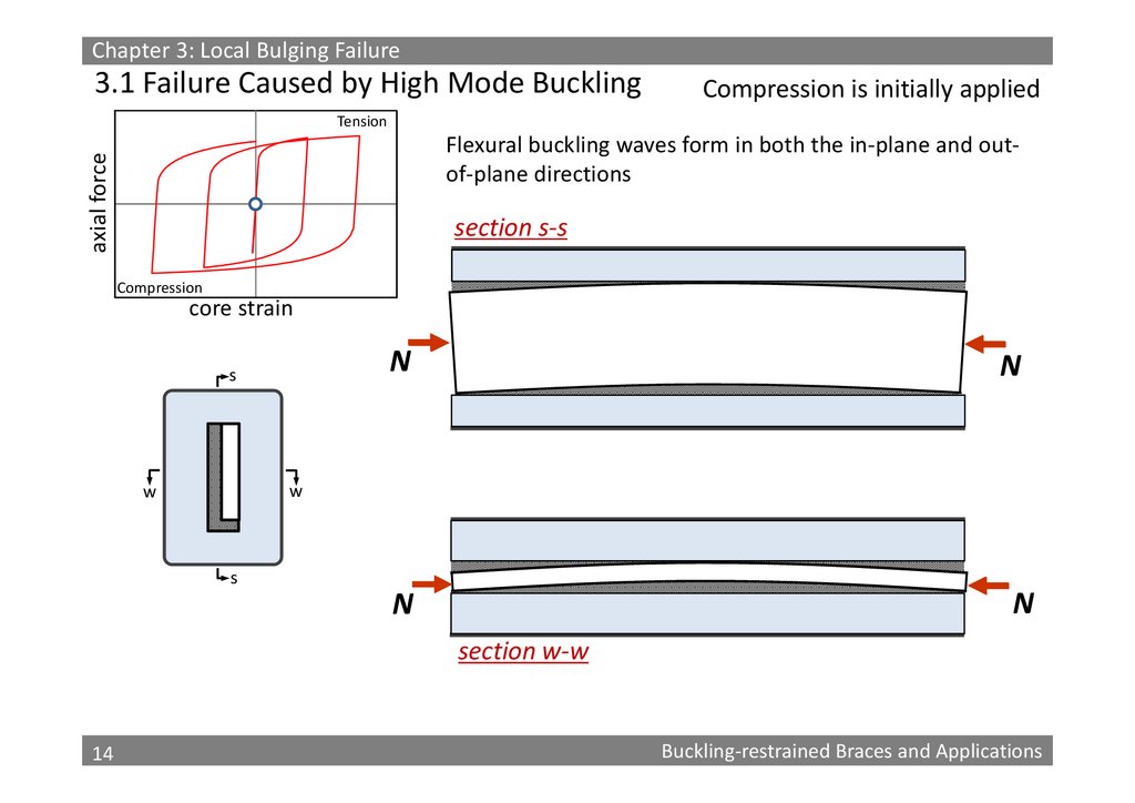
Chapter 3: Local Bulging Failure3.1 Failure Caused by High Mode Buckling
Compression is initially applied
Tension
axial force
Flexural buckling waves form in both the in‐plane and out‐
of‐plane directions
section s‐s
Compression
core strain
N
s
N
w
w
s
N
N
section w‐w
14
14
Buckling‐restrained Braces and Applications
15.
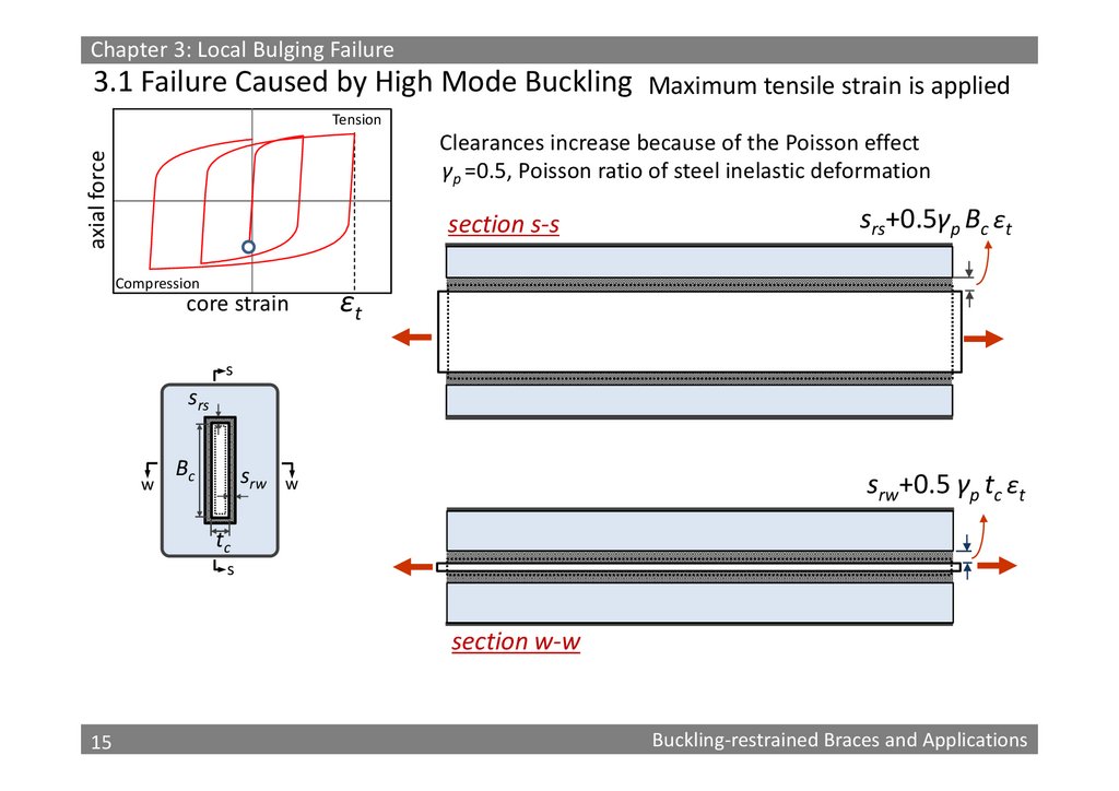
Chapter 3: Local Bulging Failure3.1 Failure Caused by High Mode Buckling Maximum tensile strain is applied
Tension
axial force
Clearances increase because of the Poisson effect
γp =0.5, Poisson ratio of steel inelastic deformation
section s‐s
Compression
core strain
srs+0.5γp Bc ɛt
ɛt
s
srs
w
Bc
srw
srw+0.5 γp tc ɛt
w
tc
s
section w‐w
15
15
Buckling‐restrained Braces and Applications
16.
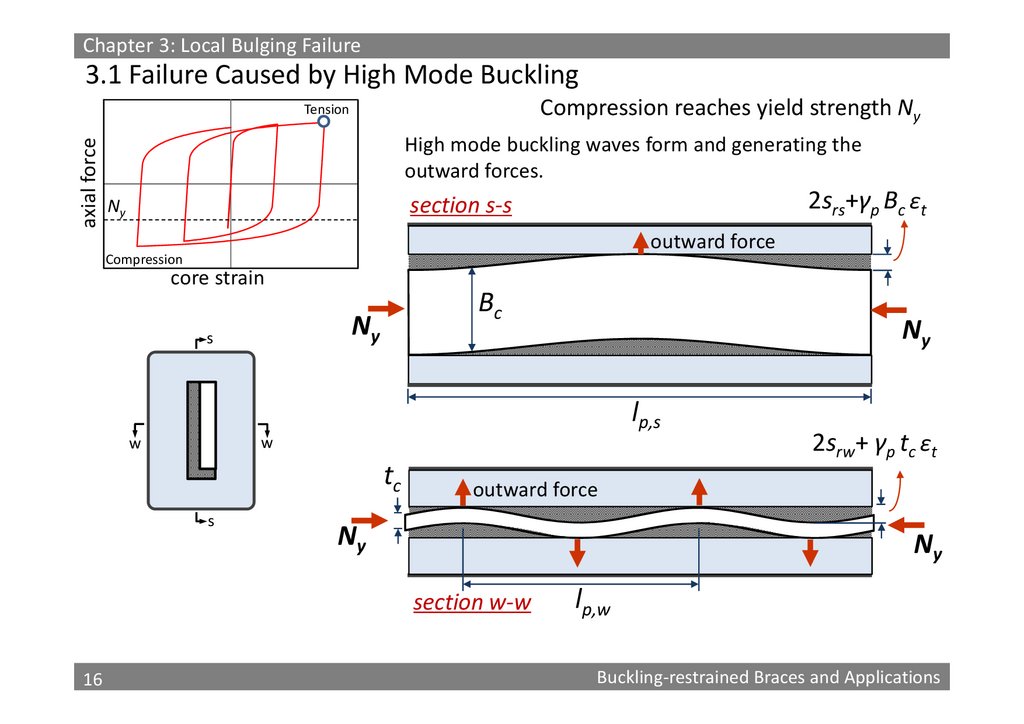
Chapter 3: Local Bulging Failure3.1 Failure Caused by High Mode Buckling
Compression reaches yield strength Ny
axial force
Tension
High mode buckling waves form and generating the
outward forces.
2srs+γp Bc ɛt
section s‐s
Ny
outward force
Compression
core strain
Bc
Ny
s
Ny
lp,s
w
w
tc
s
outward force
Ny
Ny
section w‐w
16
16
2srw+ γp tc ɛt
lp,w
Buckling‐restrained Braces and Applications
17.
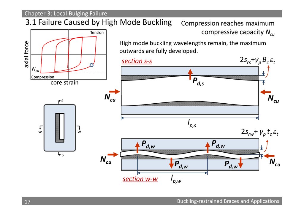
Chapter 3: Local Bulging Failure3.1 Failure Caused by High Mode Buckling
axial force
Tension
Compression reaches maximum
compressive capacity Ncu
High mode buckling wavelengths remain, the maximum
outwards are fully developed.
2srs+γp Bc ɛt
section s‐s
Ncu
Compression
Pd,s
core strain
Ncu
s
Ncu
lp,s
Pd,w
Pd,w
s
Ncu
Pd,w
section w‐w
17
17
2srw+ γp tc ɛt
w
w
Pd,w
Ncu
lp,w
Buckling‐restrained Braces and Applications
18.
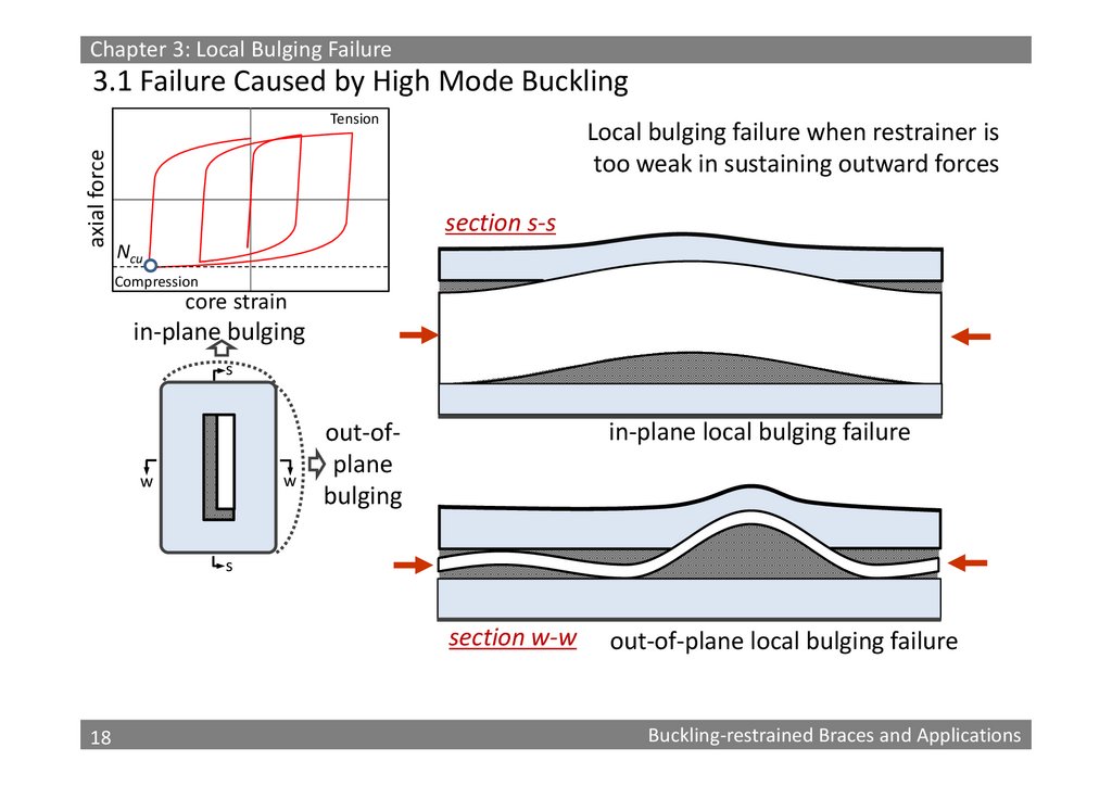
Chapter 3: Local Bulging Failure3.1 Failure Caused by High Mode Buckling
axial force
Tension
Local bulging failure when restrainer is
too weak in sustaining outward forces
section s‐s
Ncu
Compression
core strain
in‐plane bulging
s
w
w
in‐plane local bulging failure
out‐of‐
plane
bulging
s
section w‐w
18
18
out‐of‐plane local bulging failure
Buckling‐restrained Braces and Applications
19.
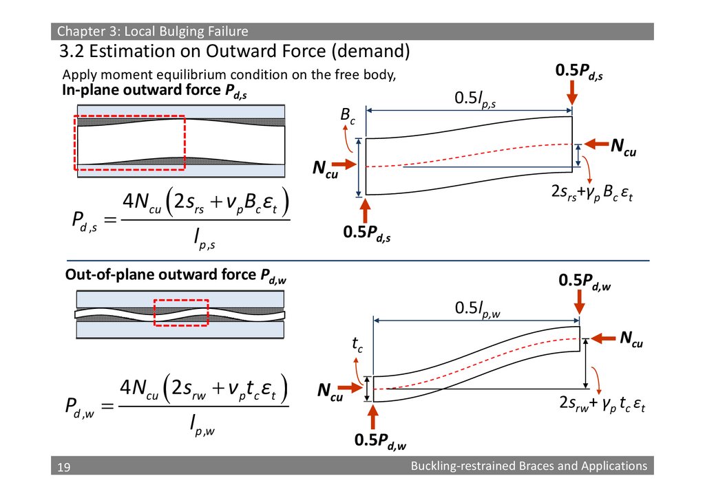
Chapter 3: Local Bulging Failure3.2 Estimation on Outward Force (demand)
0.5Pd,s
Apply moment equilibrium condition on the free body,
In‐plane outward force Pd,s
Bc
Pd ,s
4Ncu 2 srs ν pBc εt
0.5lp,s
Ncu
Ncu
2srs+γp Bc ɛt
0.5Pd,s
l p ,s
Out‐of‐plane outward force Pd,w
0.5Pd,w
0.5lp,w
tc
Pd ,w
19
19
4Ncu 2 srw ν pt c εt
lp ,w
Ncu
Ncu
2srw+ γp tc ɛt
0.5Pd,w
Buckling‐restrained Braces and Applications
20.
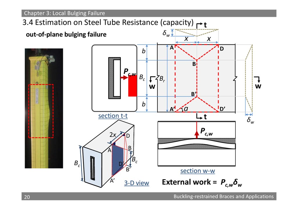
Chapter 3: Local Bulging Failure3.4 Estimation on Steel Tube Resistance (capacity)
δw
out‐of‐plane bulging failure
t
x
x
A
b
D
B
Pc,w
Bc
w
Br
w
B’
b
section t‐t
2x
20
20
D’
t
δw
B
D’
A’
a
Pc,w
D
A
Bc
A’
Bc
B’
3‐D view
section w‐w
External work = Pc,wδw
Buckling‐restrained Braces and Applications
21.
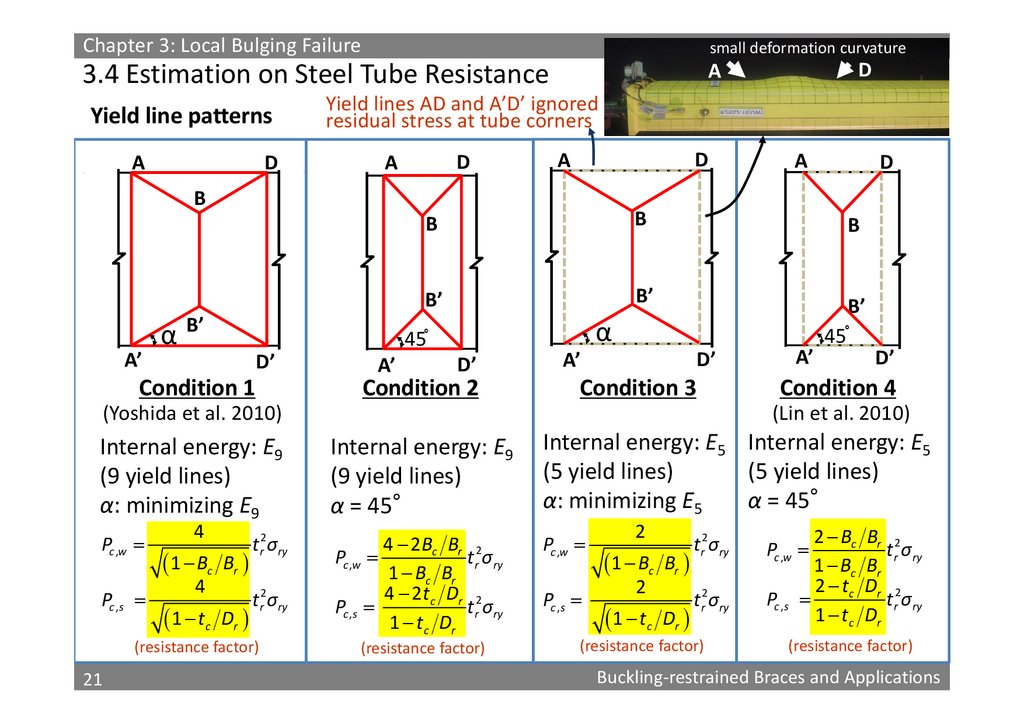
Chapter 3: Local Bulging Failuresmall deformation curvature
3.4 Estimation on Steel Tube Resistance
A
Yield line patterns
D
A
Yield lines AD and A’D’ ignored
residual stress at tube corners
D
A
D
A
B
A’
α
B’
Condition 1
A’
A
D
B
B
B
B’
B’
B’
45。
D’
D
α
D’
Condition 2
A’
D’
A’
Condition 3
(Yoshida et al. 2010)
45。
D’
Condition 4
(Lin et al. 2010)
Internal energy: E9
(9 yield lines)
α: minimizing E9
Internal energy: E9
(9 yield lines)
α = 45°
Internal energy: E5 Internal energy: E5
(5 yield lines)
(5 yield lines)
α: minimizing E5
α = 45°
Pc ,w
4 2 Bc Br 2
Pc ,w
t r σry
1 Bc Br
4 2t c Dr 2
Pc ,s
t r σry
1 t c Dr
Pc ,w
Pc ,s
4
1 Bc
Br
4
1 t c
Dr
t r2σry
t r2σry
(resistance factor)
21
21
(resistance factor)
Pc ,s
2
1 Bc
Br
2
1 t c
Dr
2 Bc
1 Bc
2 tc
1 tc
t r2σry
Pc ,w
t r2σry
Pc ,s
(resistance factor)
Br 2
t r σry
Br
Dr 2
t r σry
Dr
(resistance factor)
Buckling‐restrained Braces and Applications
22.
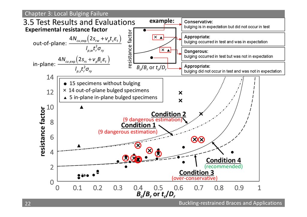
Chapter 3: Local Bulging Failureexample:
Experimental resistance factor
out‐of‐plane:
in‐plane:
4Ncu ,exp 2 srw ν pt c εt
2
p ,w r ry
l tσ
4Ncu ,exp 2 srs ν pBc εt
14
lp ,st r2σry
resistance factor
3.5 Test Results and Evaluations
Conservative:
bulging is in expectation but did not occur in test
Appropriate:
×▲
bulging occurred in test and was in expectation
×▲
Dangerous:
bulging occurred in test but was not in expectation
Appropriate:
Bc/Br or tc/Dr
bulging did not occur in test and was not in expectation
15 specimens without bulging
× 14 out‐of‐plane bulged specimens
▲ 5 in‐plane in‐plane bulged specimens
12
resistance factor
10
Condition 2
(9 dangerous estimation)
8
Condition 1
(9 dangerous estimation)
6
4
Condition 4
(recommended)
2
0
22
22
Condition 3
(over‐conservative)
0
0.1
0.2
0.3
0.4 0.5 0.6
Bc/Br or tc/Dr
0.7
0.8
0.9
1
Buckling‐restrained Braces and Applications
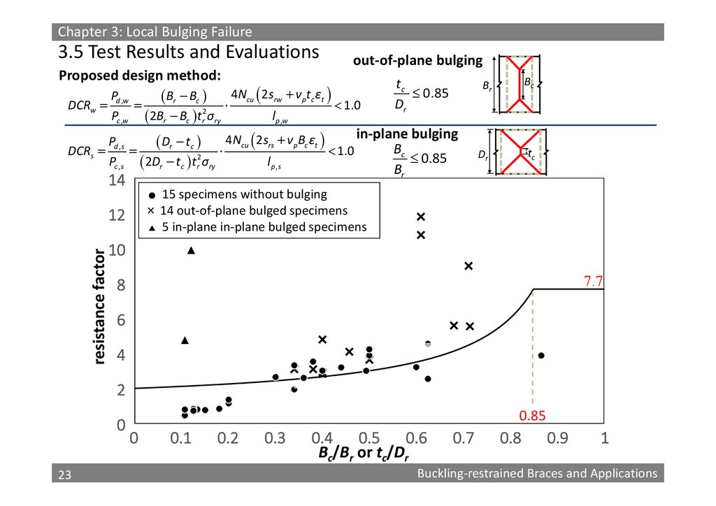
23.
Chapter 3: Local Bulging Failure3.5 Test Results and Evaluations
Proposed design method:
Pd ,w
Br Bc
Pc ,w 2Br Bc tr2σry
DCRw
4Ncu 2srw ν ptc εt
lp ,w
out‐of‐plane bulging
1.0
tc
0.85
Dr
Bc
Br
in‐plane bulging
4Ncu 2srs ν pBc εt
Pd ,s
Dr tc
Bc
1.0
DCRs
0.85
Pc ,s 2Dr tc tr2σry
lp ,s
tc
Dr
Br
14
15 specimens without bulging
× 14 out‐of‐plane bulged specimens
▲ 5 in‐plane in‐plane bulged specimens
12
resistance factor
10
7.7
8
6
4
2
0
23
23
0.85
0
0.1
0.2
0.3
0.4 0.5 0.6
Bc/Br or tc/Dr
0.7
0.8
0.9
1
Buckling‐restrained Braces and Applications
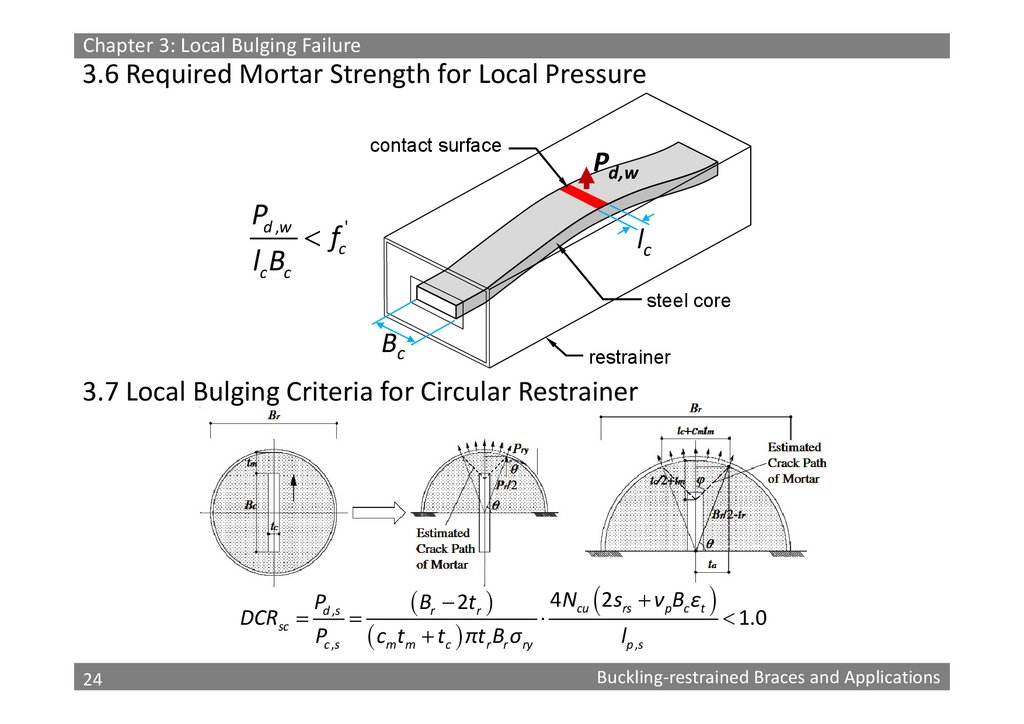
24.
Chapter 3: Local Bulging Failure3.6 Required Mortar Strength for Local Pressure
contact surface
Pd ,w
fc'
lc Bc
Pd,w
lc
steel core
Bc
restrainer
3.7 Local Bulging Criteria for Circular Restrainer
4Ncu 2srs ν pBc εt
Pd ,s
Br 2tr
DCRsc
1.0
Pc ,s cmtm tc πtr Br σry
lp , s
24
24
Buckling‐restrained Braces and Applications
25.
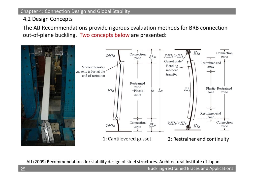
Chapter 4: Connection Design and Global Stability4.2 Design Concepts
The AIJ Recommendations provide rigorous evaluation methods for BRB connection
out‐of‐plane buckling. Two concepts below are presented:
JEIB
Connection
zone
L0
Gusset plate
Bending
moment
transfer
Moment transfer
capacity is lost at the
end of restrainer
EIB
JEIB
Restrained
zone
=Plastic
zone
Connection
zone
KRg
JEIB > EIB
lB
L0
1: Cantilevered gusset
L0
Connection
zone
Restrainer-end
zone
Plastic Restrained
zone
zone
EIB
JEIB > EIB
Restrainer-end
zone
KRg
Connection
zone
2: Restrainer end continuity
AIJ (2009) Recommendations for stability design of steel structures. Architectural Institute of Japan.
25
Buckling‐restrained Braces and Applications
25
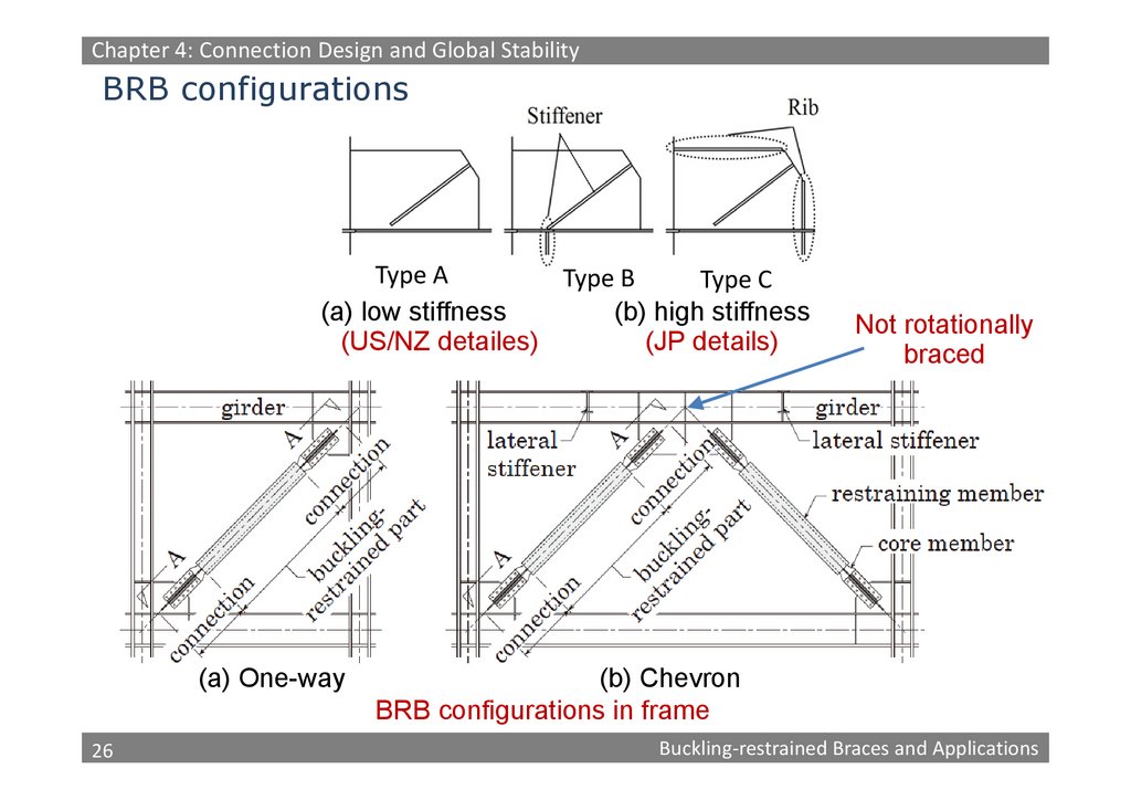
26.
Chapter 4: Connection Design and Global StabilityBRB configurations
Type A
Type B
Type C
(a) low stiffness
(b) high stiffness
(US/NZ detailes)
(JP details)
(a) One-way
26
26
Not rotationally
braced
(b) Chevron
BRB configurations in frame
Buckling‐restrained Braces and Applications
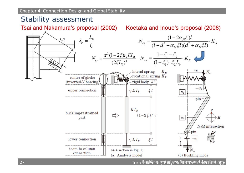
27.
Chapter 4: Connection Design and Global StabilityStability assessment
Tsai and Nakamura’s proposal (2002)
r
Koetaka and Inoue’s proposal (2008)
L0
ic
N cr
2 (1 2 )rJ EI B
N cr
(2 L0 )2
27
27
(1 2 N )l
KR
*
*
(l d N l )( d N l )
N cr
1 1 2
KR
(1 1 ) 2 L0
Braces and
Toru Buckling‐restrained
Takeuchi, Tokyo Institute
of Applications
Technology
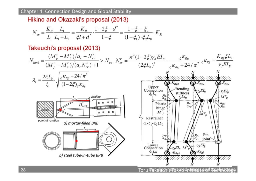
28.
Chapter 4: Connection Design and Global StabilityHikino and Okazaki’s proposal (2013)
K R L1
K R 1 2 d *
1 1 2
N cr
KR
1
(1 1 ) 2 L0
L1 L1 L2 l d *
Takeuchi’s proposal (2013)
N lim1
( M pr M 0r ) ar N crr
( M pr M 0r ) ( ar N crB ) 1
2 L0
r
ic
N cu
K Rg L0
2 (1 2 ) J EI B
Rg
N
2 Rg
J EI B
(2 L0 )2
24
/
Rg
r
cr
Rg 24 / 2
(1 2 ) Rg
Lin
yielding
Dneck
point of rotation
a) mortar‐filled BRB
Lin
b) steel tube‐in‐tube BRB
28
28
Braces and
Toru Buckling‐restrained
Takeuchi, Tokyo Institute
of Applications
Technology
29.
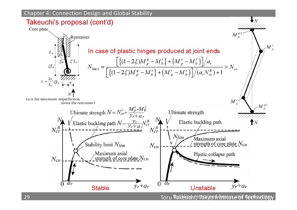
Chapter 4: Connection Design and Global StabilityTakeuchi’s proposal (cont’d)
In case of plastic hinges produced at joint ends
N lim 2
(1 2 ) M pg M 0r M pr M 0r ar
N cu
g
r
r
r
B
(1 2 ) M p M 0 M p M 0 ( ar N cr ) 1
Stable
29
29
Unstable
Braces and
Toru Buckling‐restrained
Takeuchi, Tokyo Institute
of Applications
Technology
30.
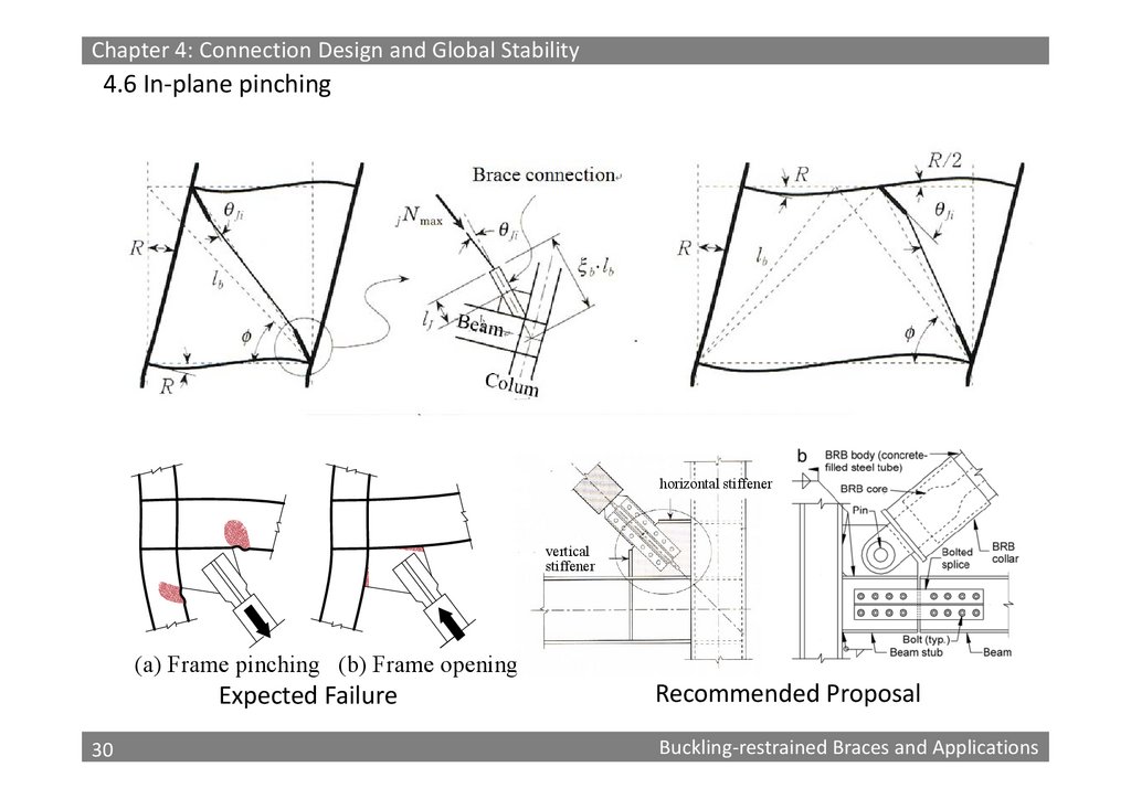
Chapter 4: Connection Design and Global Stability4.6 In‐plane pinching
horizontal stiffener
vertical
stiffener
(a) Frame pinching (b) Frame opening
Expected Failure
30
30
Recommended Proposal
Buckling‐restrained Braces and Applications
31.
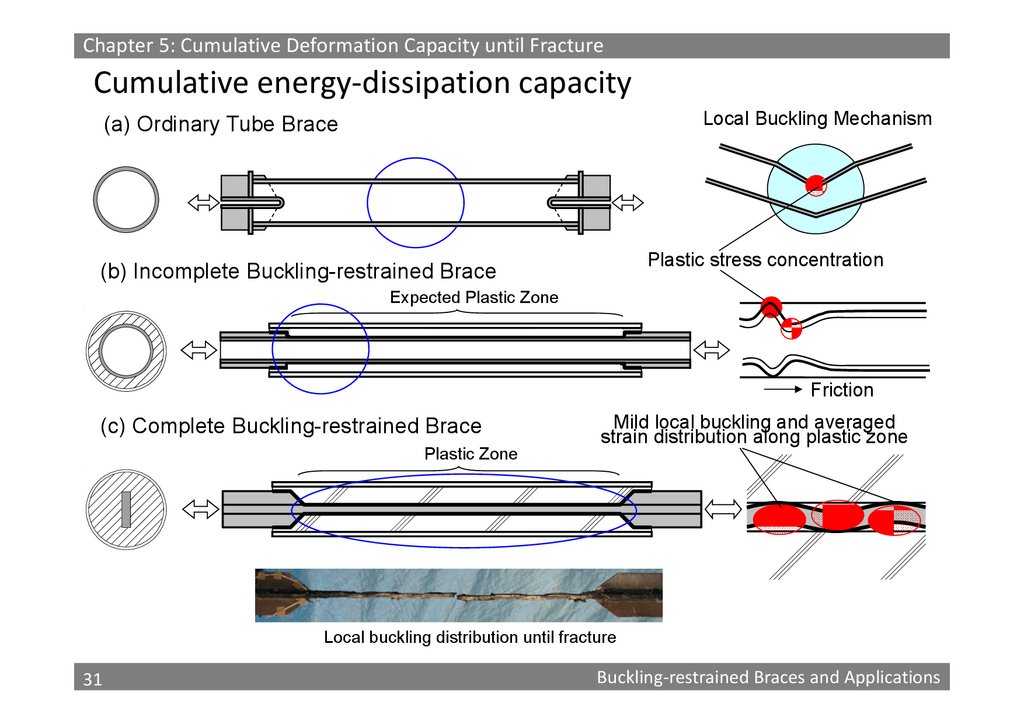
Chapter 5: Cumulative Deformation Capacity until FractureCumulative energy‐dissipation capacity
Local Buckling Mechanism
(a) Ordinary Tube Brace
Plastic stress concentration
(b) Incomplete Buckling-restrained Brace
Expected Plastic Zone
Friction
(c) Complete Buckling-restrained Brace
Plastic Zone
Mild local buckling and averaged
strain distribution along plastic zone
Local buckling distribution until fracture
31
31
Buckling‐restrained Braces and Applications
32.
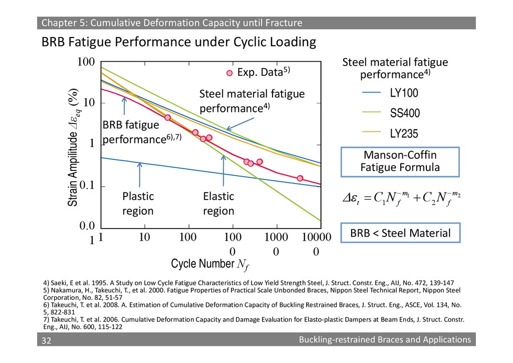
Chapter 5: Cumulative Deformation Capacity until FractureBRB Fatigue Performance under Cyclic Loading
Strain Ampilitude Δεeq (%)
100
Exp.
Steel material fatigue
performance4)
Data5)
Steel material fatigue
performance4)
10
BRB fatigue
6),7)
1 performance
0.1
0.0
11
Plastic
region
10
SS400
LY235
Manson‐Coffin
Fatigue Formula
t C1 N f m C2 N f m
Elastic
region
100
LY100
100
0
Cycle Number Nf
1
1000
0
10000
0
2
BRB < Steel Material
4) Saeki, E et al. 1995. A Study on Low Cycle Fatigue Characteristics of Low Yield Strength Steel, J. Struct. Constr. Eng., AIJ, No. 472, 139‐147
5) Nakamura, H., Takeuchi, T., et al. 2000. Fatigue Properties of Practical Scale Unbonded Braces, Nippon Steel Technical Report, Nippon Steel
Corporation, No. 82, 51‐57
6) Takeuchi, T. et al. 2008. A. Estimation of Cumulative Deformation Capacity of Buckling Restrained Braces, J. Struct. Eng., ASCE, Vol. 134, No.
5, 822‐831
7) Takeuchi, T. et al. 2006. Cumulative Deformation Capacity and Damage Evaluation for Elasto‐plastic Dampers at Beam Ends, J. Struct. Constr.
Eng., AIJ, No. 600, 115‐122
32
32
Buckling‐restrained Braces and Applications
33.
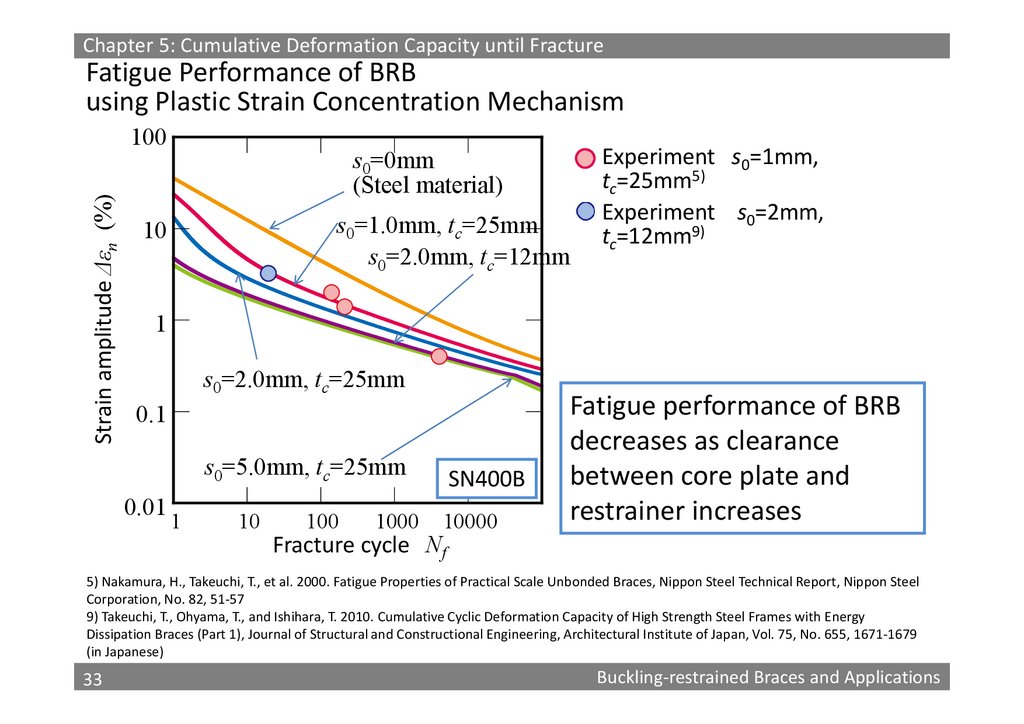
Chapter 5: Cumulative Deformation Capacity until FractureFatigue Performance of BRB
using Plastic Strain Concentration Mechanism
Strain amplitude Δεn (%)
100
s0=0mm
(Steel material)
s0=1.0mm, tc=25mm
s0=2.0mm, tc=12mm
10
Experiment s0=1mm,
tc=25mm5)
Experiment s0=2mm,
tc=12mm9)
1
s0=2.0mm, tc=25mm
0.1
s0=5.0mm, tc=25mm
0.01
1
10
100
1000
SN400B
10000
Fatigue performance of BRB
decreases as clearance
between core plate and
restrainer increases
Fracture cycle Nf
5) Nakamura, H., Takeuchi, T., et al. 2000. Fatigue Properties of Practical Scale Unbonded Braces, Nippon Steel Technical Report, Nippon Steel
Corporation, No. 82, 51‐57
9) Takeuchi, T., Ohyama, T., and Ishihara, T. 2010. Cumulative Cyclic Deformation Capacity of High Strength Steel Frames with Energy
Dissipation Braces (Part 1), Journal of Structural and Constructional Engineering, Architectural Institute of Japan, Vol. 75, No. 655, 1671‐1679
(in Japanese)
33
33
Buckling‐restrained Braces and Applications
34.
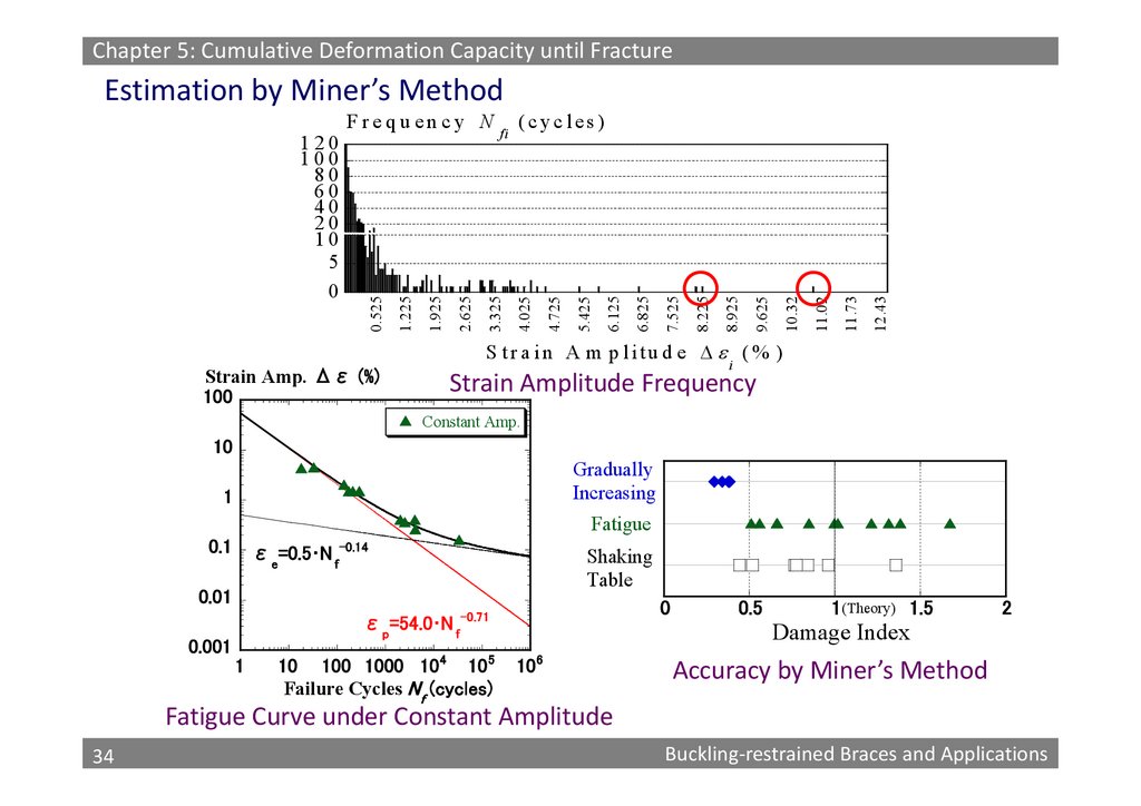
Chapter 5: Cumulative Deformation Capacity until FractureEstimation by Miner’s Method
12.43
11.73
11.02
10.32
9.625
8.925
8.225
7.525
6.825
6.125
5.425
4.725
(cyc les)
4.025
fi
3.325
2.625
1.925
1.225
0.525
120
100
80
60
40
20
10
5
0
F re q u en cy N
S tr a in A m p litu d e (% )
Strain Amp. Δε (%)
100
i
Strain Amplitude Frequency
Constant Amp.
10
Gradually
Increasing
1
Fatigue
0.1
εe=0.5 N f-0.14
Shaking
Table
0.01
0
εp=54.0 N f-0.71
0.001
1
10 100 1000 10 4 10 5
Failure Cycles N f (cycles)
0.5
1(Theory) 1.5
2
Damage Index
10 6
Accuracy by Miner’s Method
Fatigue Curve under Constant Amplitude
34
34
Buckling‐restrained Braces and Applications
35.
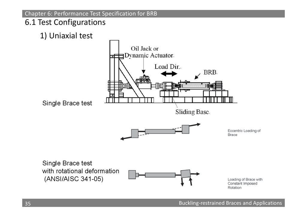
Chapter 6: Performance Test Specification for BRB6.1 Test Configurations
1) Uniaxial test
Single Brace test
Single Brace test
with rotational deformation
(ANSI/AISC 341-05)
35
35
Buckling‐restrained Braces and Applications
36.
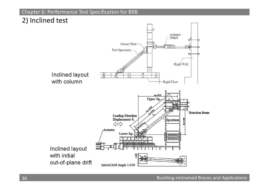
Chapter 6: Performance Test Specification for BRB2) Inclined test
Inclined layout
with column
Inclined layout
with initial
out-of-plane drift
36
36
Buckling‐restrained Braces and Applications
37.
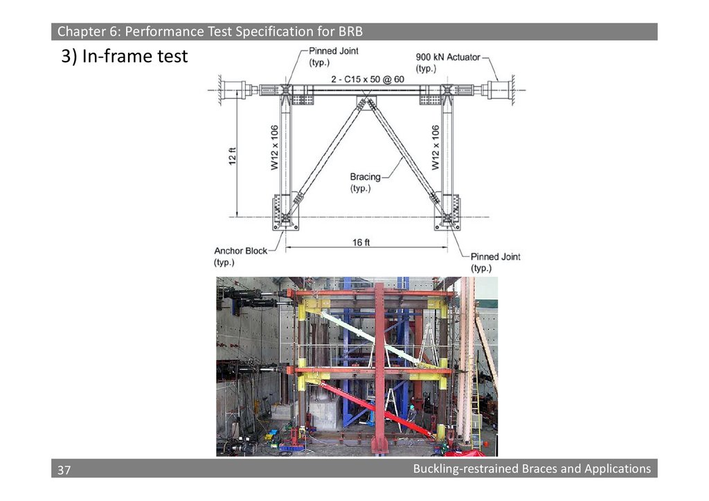
Chapter 6: Performance Test Specification for BRB3) In‐frame test
37
37
Buckling‐restrained Braces and Applications
38.
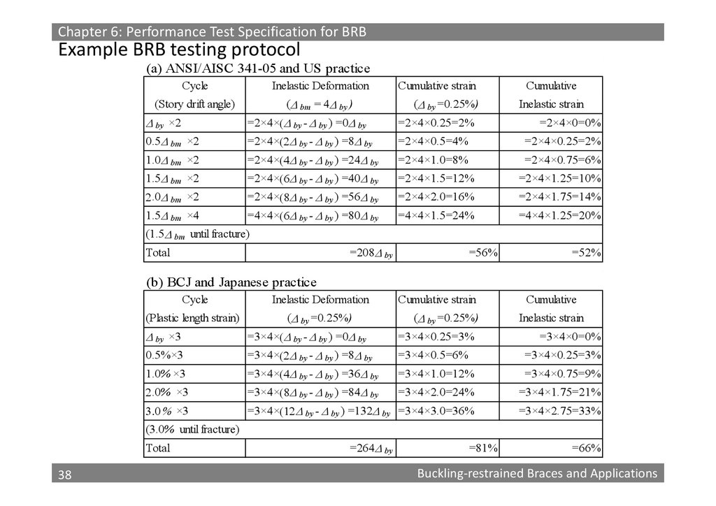
Chapter 6: Performance Test Specification for BRBExample BRB testing protocol
(a) ANSI/AISC 341-05 and US practice
Cycle
Inelastic Deformation
(Story drift angle)
( bm = 4 by )
Cumulative strain
( by =0.25%)
Cumulative
Inelastic strain
by ×2
=2×4× by - by ) =0 by
=2×4×0.25=2%
0.5 bm ×2
=2×4× by - by ) =8 by
=2×4×0.5=4%
=2×4×0.25=2%
1.0 bm ×2
=2×4× by - by ) =24 by
=2×4×1.0=8%
=2×4×0.75=6%
1.5 bm ×2
=2×4× by - by ) =40 by
=2×4×1.5=12%
=2×4×1.25=10%
.0 bm ×2
=2×4× by - by ) =56 by
=2×4×2.0=16%
=2×4×1.75=14%
1.5 bm ×4
=4×4× by - by ) =80 by
=4×4×1.5=24%
=4×4×1.25=20%
=2×4×0=0%
(1.5 bm until fracture)
=208 by
Total
=56%
=52%
(b) BCJ and Japanese practice
Cycle
Inelastic Deformation
(Plastic length strain)
( by =0.25%)
Cumulative strain
( by =0.25%)
Cumulative
Inelastic strain
by ×3
=3×4× by - by ) =0 by
=3×4×0.25=3%
0.5%×3
=3×4× by - by ) =8 by
=3×4×0.5=6%
=3×4×0.25=3%
1.0% ×3
=3×4× by - by ) =36 by
=3×4×1.0=12%
=3×4×0.75=9%
.0% ×3
=3×4× by - by ) =84 by
=3×4×2.0=24%
=3×4×1.75=21%
×3
=3×4× by - by ) =132 by =3×4×3.0=36%
=3×4×2.75=33%
=3×4×0=0%
(3.0% until fracture)
Total
38
38
=264 by
=81%
=66%
Buckling‐restrained Braces and Applications
39.
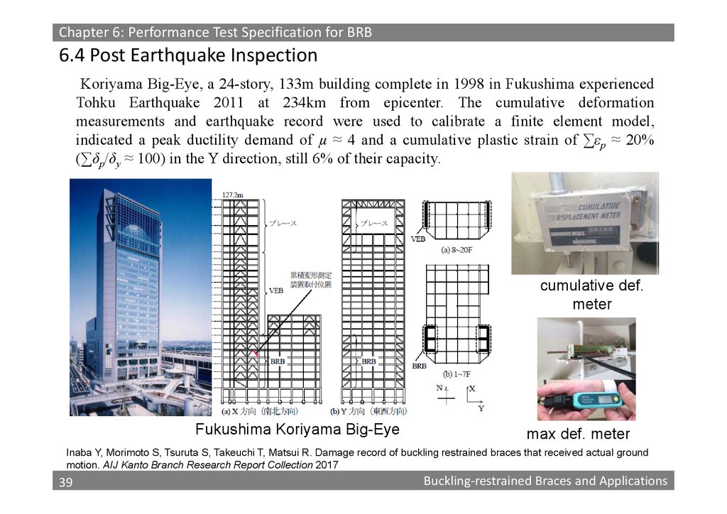
Chapter 6: Performance Test Specification for BRB6.4 Post Earthquake Inspection
Koriyama Big-Eye, a 24-story, 133m building complete in 1998 in Fukushima experienced
Tohku Earthquake 2011 at 234km from epicenter. The cumulative deformation
measurements and earthquake record were used to calibrate a finite element model,
indicated a peak ductility demand of µ ≈ 4 and a cumulative plastic strain of ∑εp ≈ 20%
(∑δp/δy ≈ 100) in the Y direction, still 6% of their capacity.
cumulative def.
meter
Fukushima Koriyama Big-Eye
max def. meter
Inaba Y, Morimoto S, Tsuruta S, Takeuchi T, Matsui R. Damage record of buckling restrained braces that received actual ground
motion. AIJ Kanto Branch Research Report Collection 2017
39
39
Buckling‐restrained Braces and Applications
40.
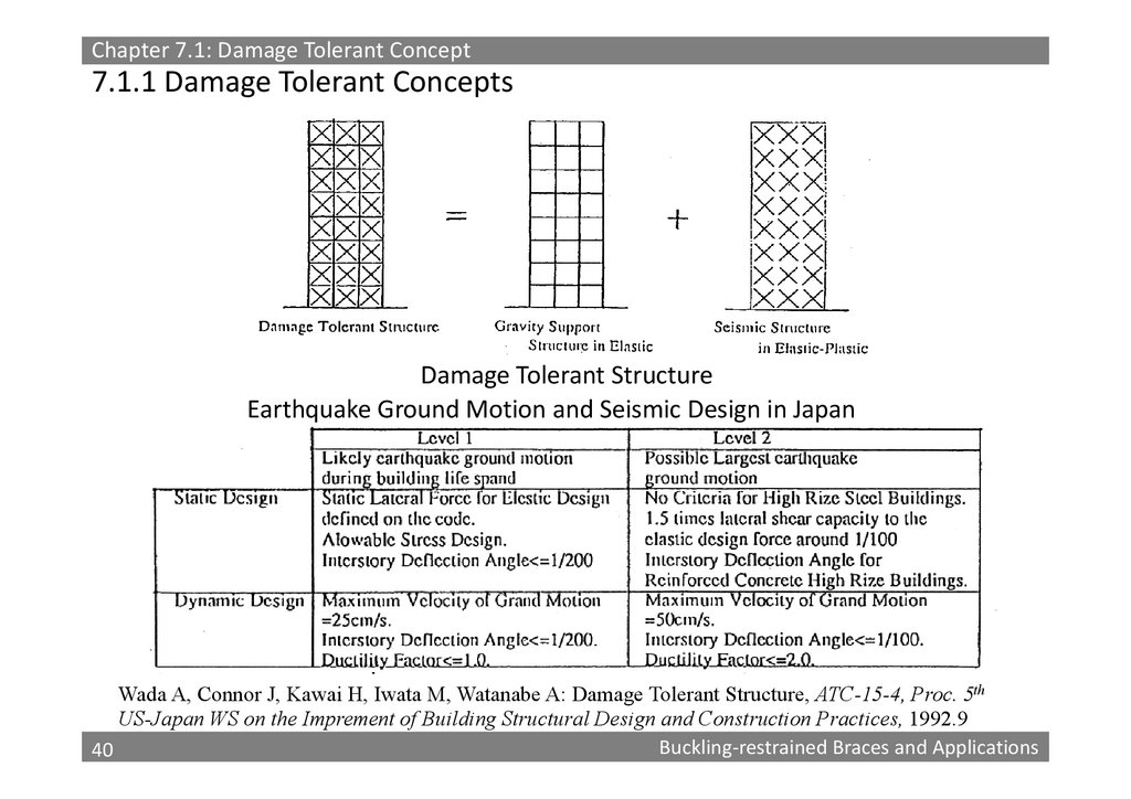
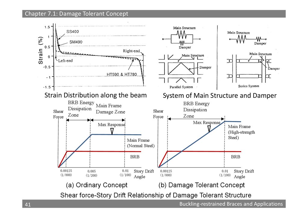
Chapter 7.1: Damage Tolerant Concept7.1.1 Damage Tolerant Concepts
Damage Tolerant Structure
Earthquake Ground Motion and Seismic Design in Japan
Wada A, Connor J, Kawai H, Iwata M, Watanabe A: Damage Tolerant Structure, ATC-15-4, Proc. 5th
US-Japan WS on the Imprement of Building Structural Design and Construction Practices, 1992.9
40
Buckling‐restrained Braces and Applications
40
41.
Chapter 7.1: Damage Tolerant ConceptStrain Distribution along the beam
BRB Energy
Main Frame
Dissipation
Shear
Damage Zone
Force Zone
System of Main Structure and Damper
Shear
Force
BRB Energy
Dissipation
Zone
Max Response
Max Response
Main Frame
(Normal Steel)
Main Frame
(High-strength
Steel)
BRB
0.00125
(1/800)
0.005
(1/200)
0.01
(1/100)
(a) Ordinary Concept
Story Drift
Angle
BRB
0.00125
(1/800)
0.01
(1/100)
Story Drift
Angle
(b) Damage Tolerant Concept
Shear force-Story Drift Relationship of Damage Tolerant Structure
41
41
Buckling‐restrained Braces and Applications
42.
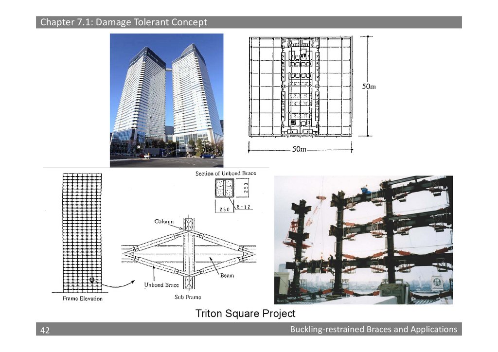
Chapter 7.1: Damage Tolerant ConceptTriton Square Project
42
42
Buckling‐restrained Braces and Applications
43.
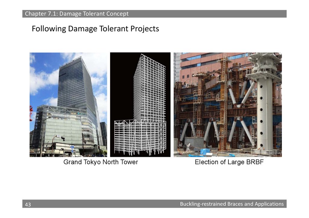
Chapter 7.1: Damage Tolerant ConceptFollowing Damage Tolerant Projects
Grand Tokyo North Tower
43
43
Election of Large BRBF
Buckling‐restrained Braces and Applications
44.
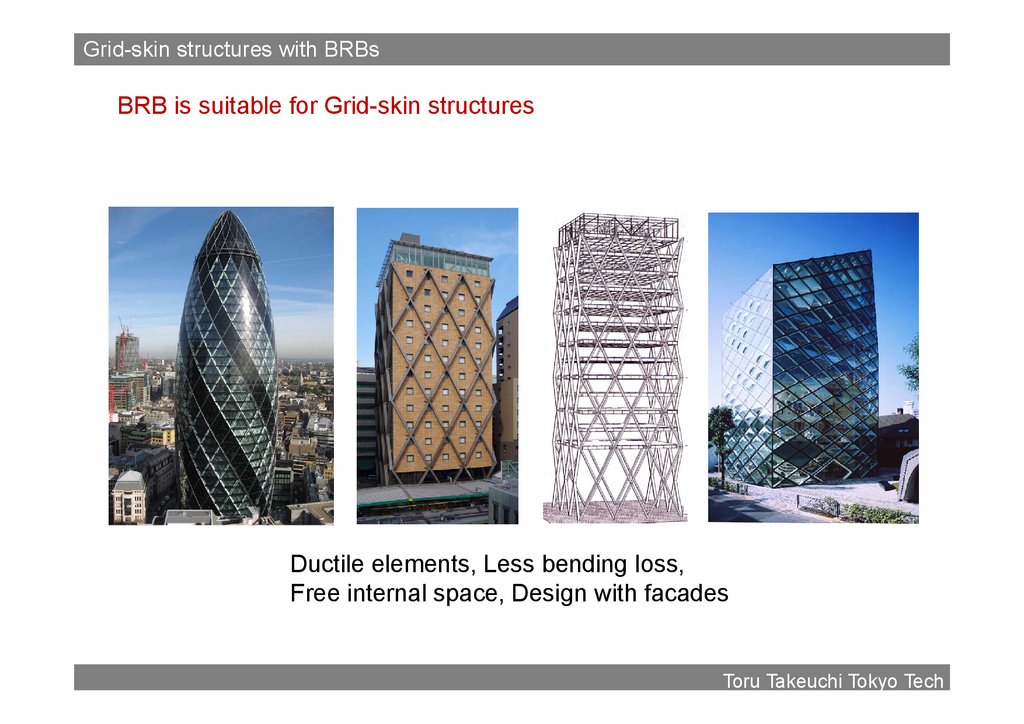
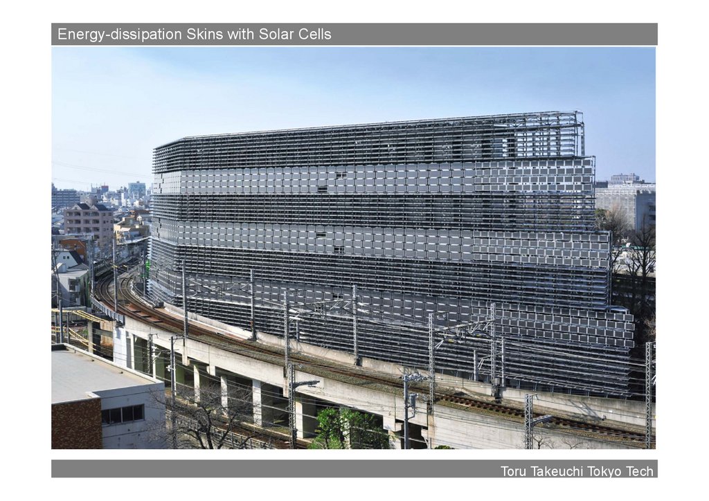
Grid-skin structures with BRBsBRB is suitable for Grid-skin structures
Ductile elements, Less bending loss,
Free internal space, Design with facades
44
Toru Takeuchi Tokyo Tech
45.
Energy-dissipation Skins with Solar Cells2. Disaster Prevention and Environmental Sustainability
Cg南側
45
Toru Takeuchi Tokyo Tech
46.
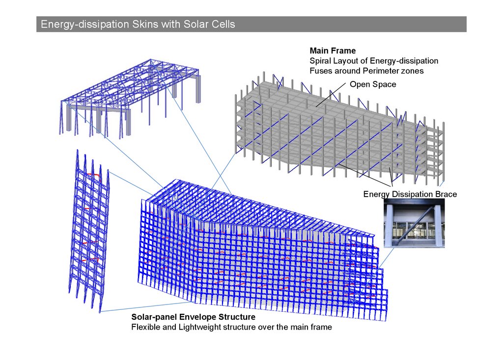
Energy-dissipation Skins with Solar Cells2. Disaster Prevention and Environmental Sustainability
Main Frame
Spiral Layout of Energy-dissipation
Fuses around Perimeter zones
Open Space
Energy Dissipation Brace
46
Solar-panel Envelope Structure
Flexible and Lightweight structure over the main frame
47.
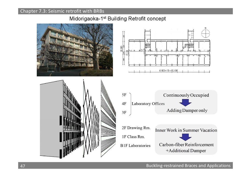
Chapter 7.3: Seismic retrofit with BRBsMidorigaoka-1st Building Retrofit concept
47
47
Buckling‐restrained Braces and Applications
48.
800800
600
600
400
400
200
200
(kN)
(kN)
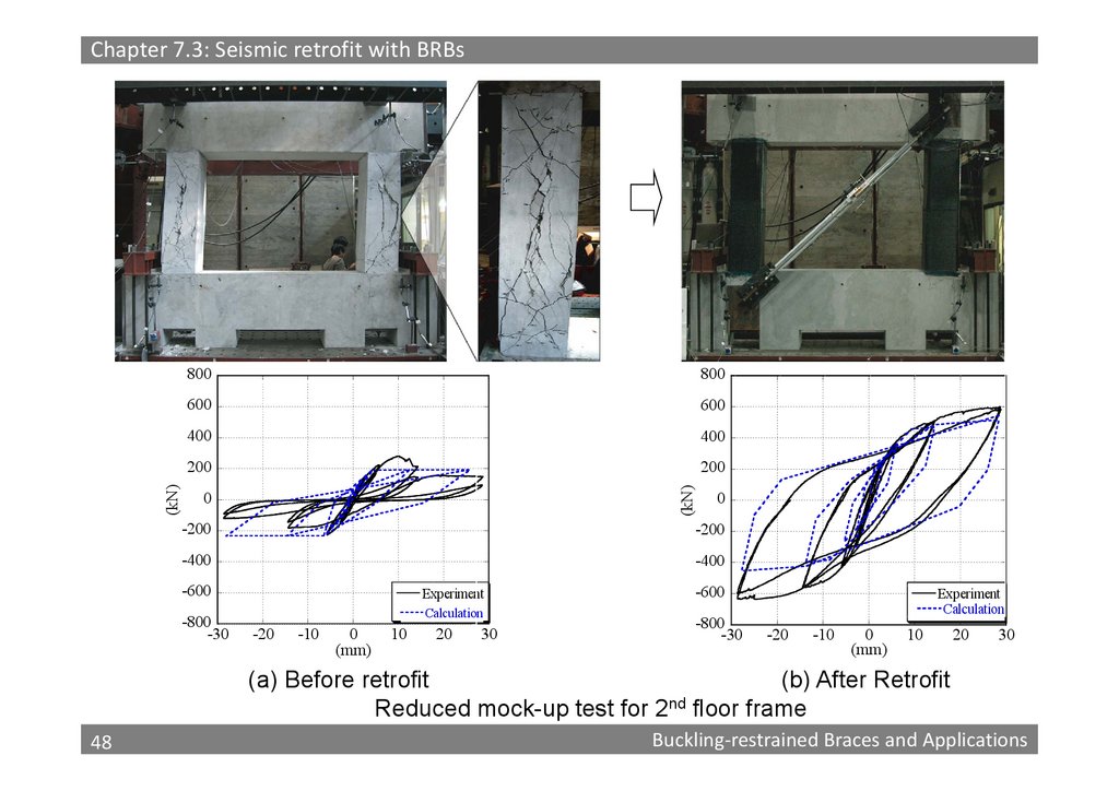
Chapter 7.3: Seismic retrofit with BRBs
0
0
-200
-200
-400
-400
-600
-800
-30
Experiment
Calculation
-20
-10
0
(mm)
10
20
30
-600
-800
-30
Experiment
Calculation
-20
-10
0
(mm)
10
20
30
(a) Before retrofit
(b) After Retrofit
Reduced mock-up test for 2nd floor frame
48
48
Buckling‐restrained Braces and Applications
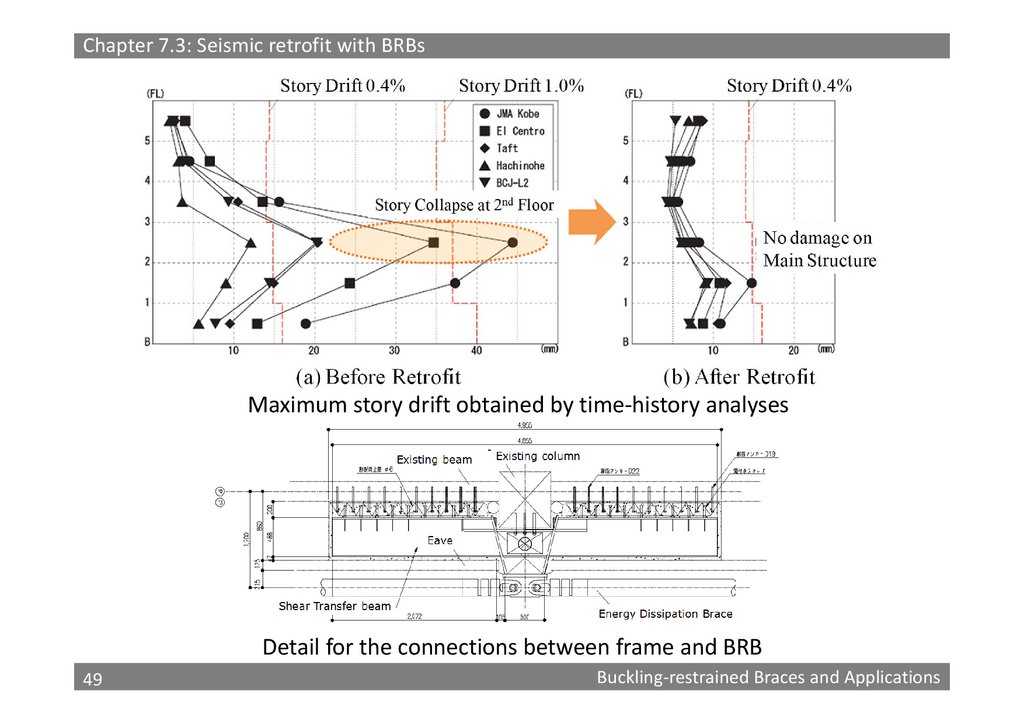
49.
Chapter 7.3: Seismic retrofit with BRBsMaximum story drift obtained by time‐history analyses
Detail for the connections between frame and BRB
49
49
Buckling‐restrained Braces and Applications
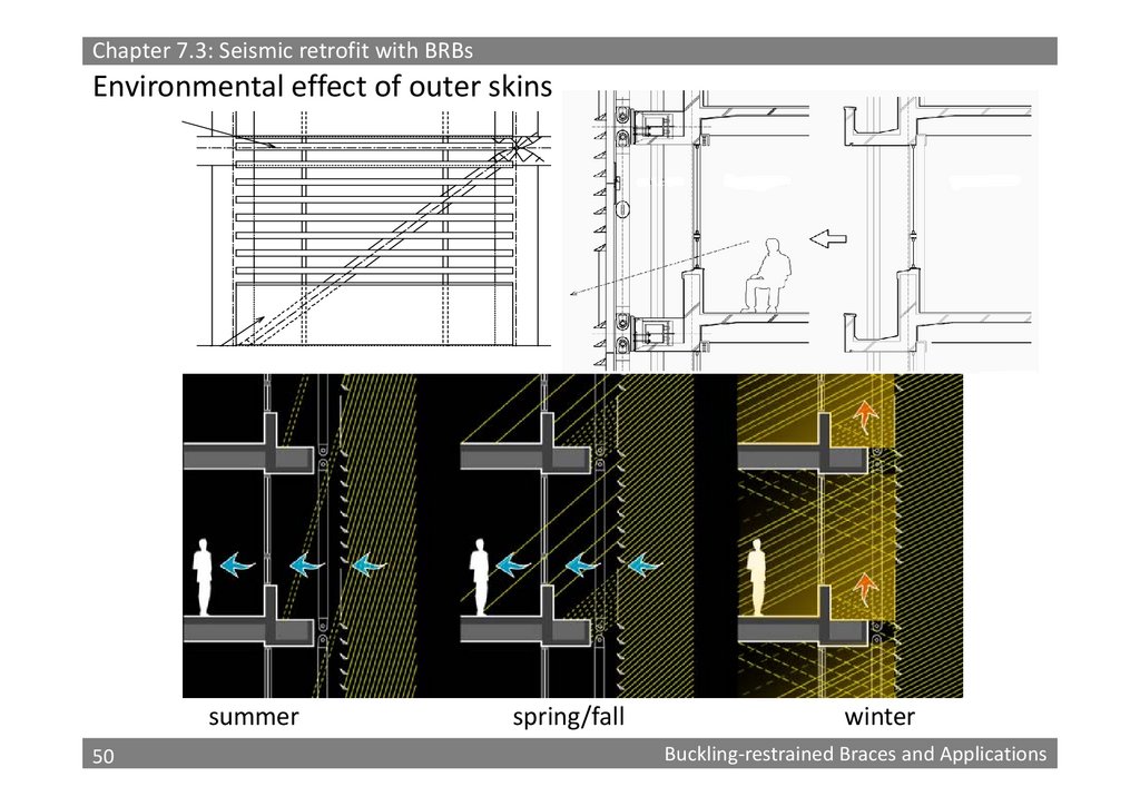
50.
Chapter 7.3: Seismic retrofit with BRBsEnvironmental effect of outer skins
summer
50
50
spring/fall
winter
Buckling‐restrained Braces and Applications
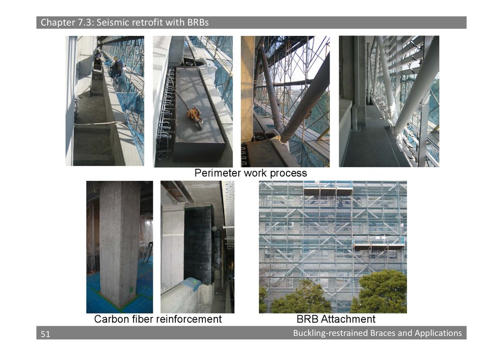
51.
Chapter 7.3: Seismic retrofit with BRBsPerimeter work process
Carbon fiber reinforcement
51
51
BRB Attachment
Buckling‐restrained Braces and Applications
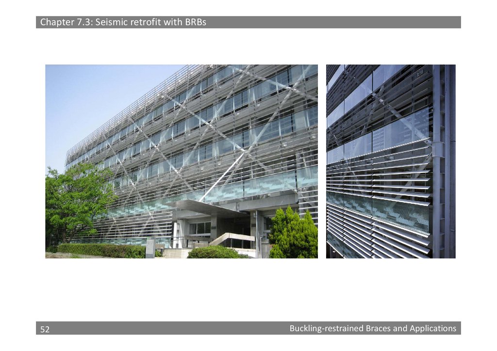
52.
Chapter 7.3: Seismic retrofit with BRBs52
52
Buckling‐restrained Braces and Applications
53.
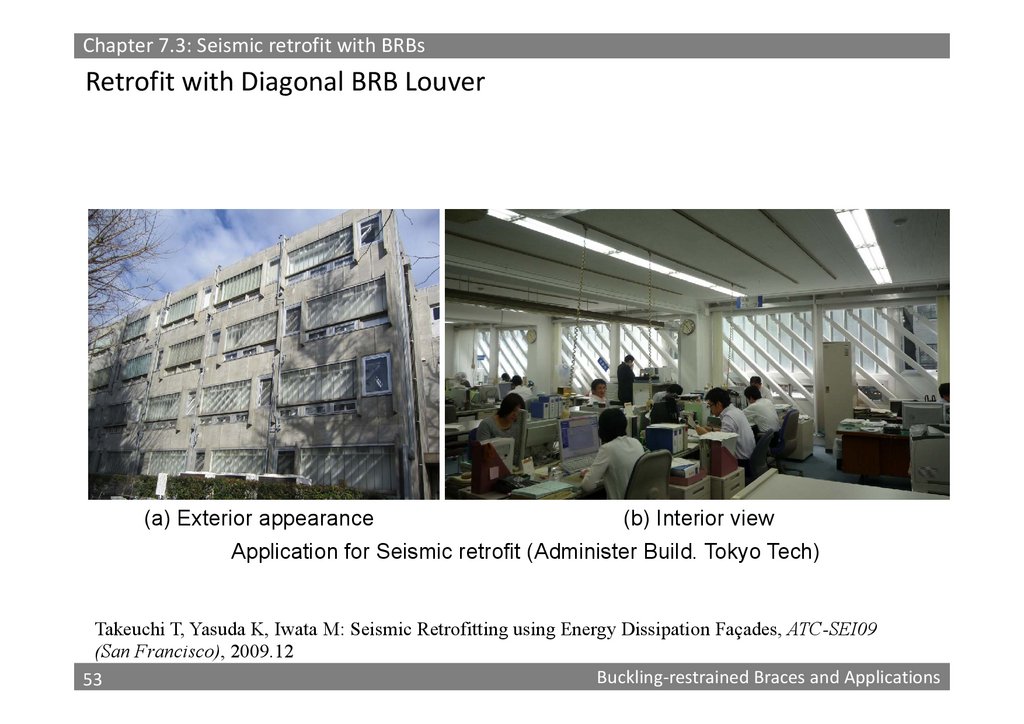
Chapter 7.3: Seismic retrofit with BRBsRetrofit with Diagonal BRB Louver
(a) Exterior appearance
(b) Interior view
Application for Seismic retrofit (Administer Build. Tokyo Tech)
Takeuchi T, Yasuda K, Iwata M: Seismic Retrofitting using Energy Dissipation Façades, ATC-SEI09
(San Francisco), 2009.12
53
Buckling‐restrained Braces and Applications
53
54.
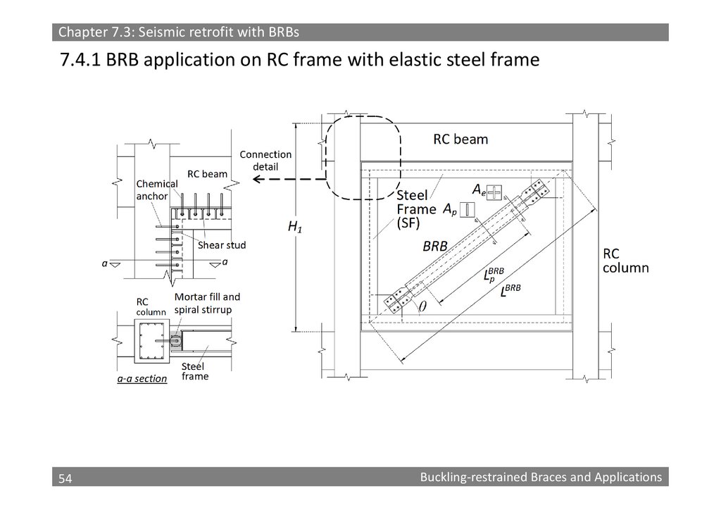
Chapter 7.3: Seismic retrofit with BRBs7.4.1 BRB application on RC frame with elastic steel frame
54
54
Buckling‐restrained Braces and Applications
55.
Chapter 7.3: Seismic retrofit with BRBsA
A
B
B
C
C
D
D
E
E
F
F
1
2
3
4
5
6
7
8
9
10
11
12
13
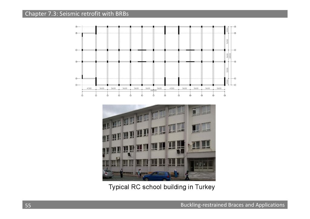
Typical RC school building in Turkey
55
55
Buckling‐restrained Braces and Applications
56.
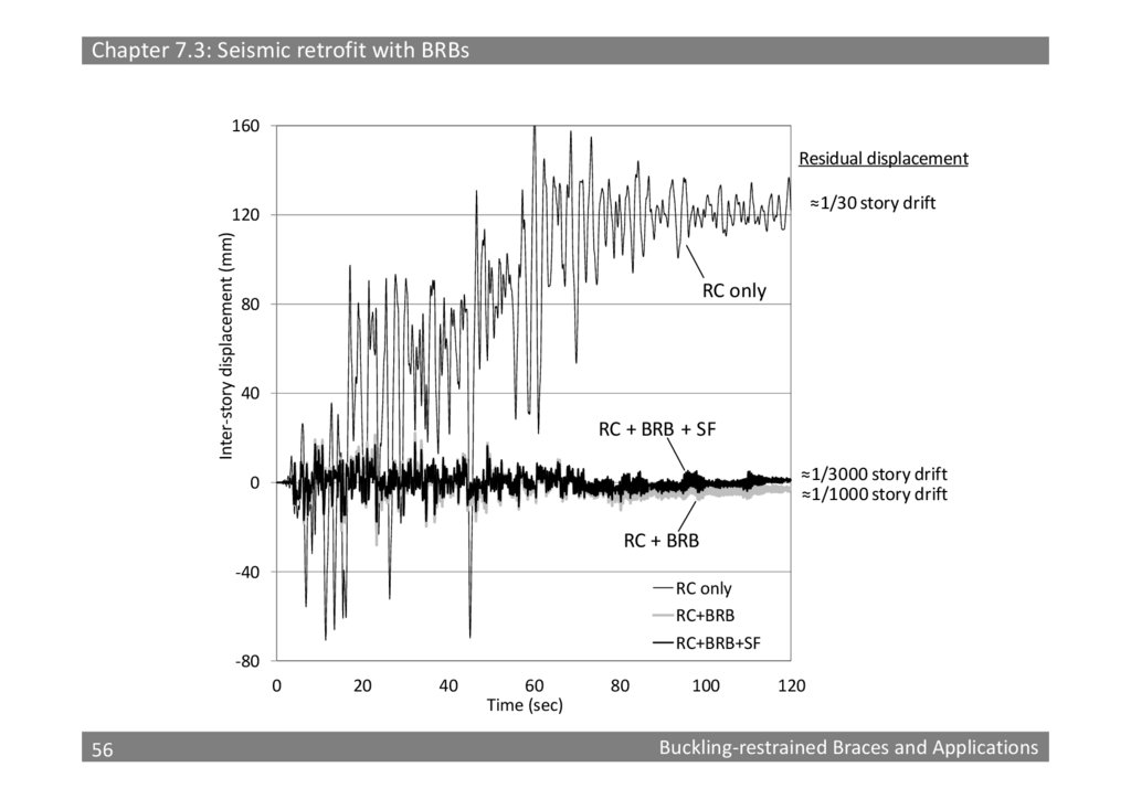
Chapter 7.3: Seismic retrofit with BRBs160
Residual displacement
≈1/30 story drift
Inter‐story displacement (mm)
120
RC only
80
40
RC + BRB + SF
≈1/3000 story drift
≈1/1000 story drift
0
RC + BRB
‐40
RC only
RC+BRB
RC+BRB+SF
‐80
0
56
56
20
40
60
Time (sec)
80
100
120
Buckling‐restrained Braces and Applications
57.
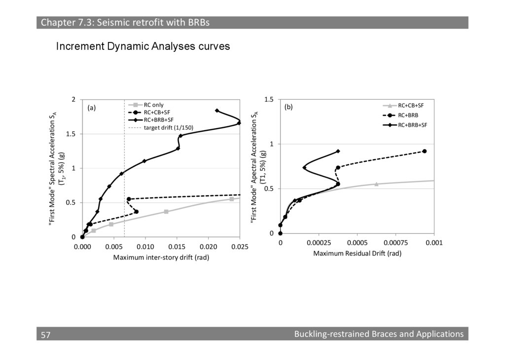
Chapter 7.3: Seismic retrofit with BRBsIncrement Dynamic Analyses curves
"First Mode" Spectral Acceleration SA
(T1, 5%) (g)
(a)
1.5
1.5
RC only
RC+CB+SF
RC+BRB+SF
target drift (1/150)
(b)
"First Mode" Apectral Acceleration SA
(T1, 5%) (g)
2
1
RC+BRB
RC+BRB+SF
1
0.5
0.5
0
0.000
57
57
RC+CB+SF
0
0.005
0.010
0.015
0.020
Maximum inter‐story drift (rad)
0.025
0
0.00025
0.0005
0.00075
Maximum Residual Drift (rad)
0.001
Buckling‐restrained Braces and Applications
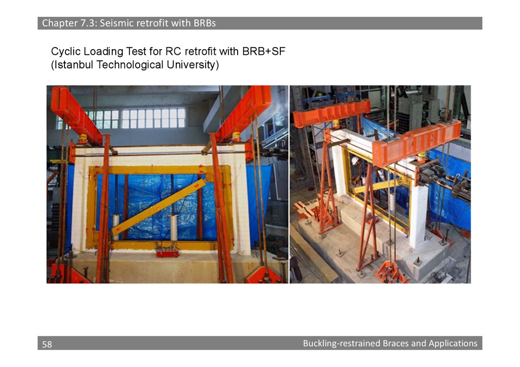
58.
Chapter 7.3: Seismic retrofit with BRBsCyclic Loading Test for RC retrofit with BRB+SF
(Istanbul Technological University)
58
58
Buckling‐restrained Braces and Applications
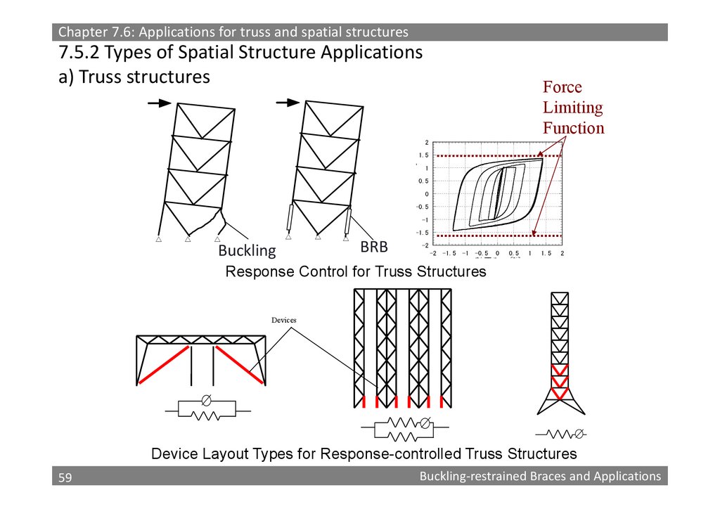
59.
Chapter 7.6: Applications for truss and spatial structures7.5.2 Types of Spatial Structure Applications
a) Truss structures
Force
Limiting
Function
2
y
1.5
1
0.5
0
-0.5
-1
△
△
△
△
Buckling
△
△
-1.5
BRB
-2
-2
-1.5
-1
0
0.5
軸歪み
-0.5
[%]
Response Control for Truss Structures
1
1.5
2
Devices
Device Layout Types for Response-controlled Truss Structures
59
59
Buckling‐restrained Braces and Applications
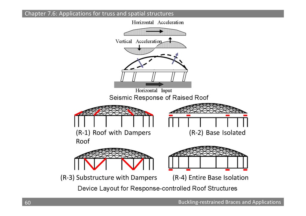
60.
Chapter 7.6: Applications for truss and spatial structuresHorizontal Acceleration
Vertical Acceleration
Horizontal Input
Seismic Response of Raised Roof
(R‐1) Roof with Dampers
Roof
(R‐3) Substructure with Dampers
(R‐2) Base Isolated
(R‐4) Entire Base Isolation
Device Layout for Response-controlled Roof Structures
60
60
Buckling‐restrained Braces and Applications
61.
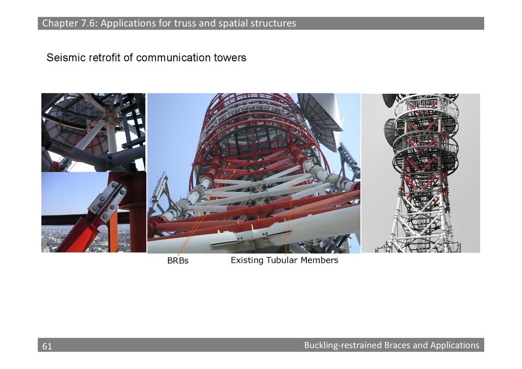
Chapter 7.6: Applications for truss and spatial structuresSeismic retrofit of communication towers
61
61
Buckling‐restrained Braces and Applications
62.
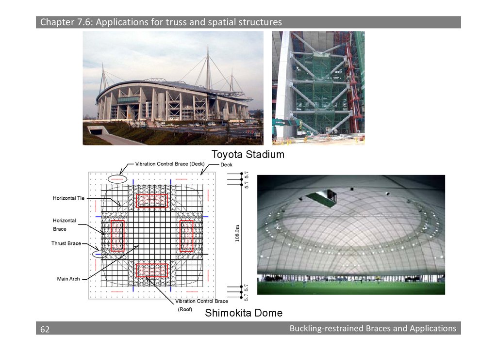
Chapter 7.6: Applications for truss and spatial structuresToyota Stadium
Deck
5.7 5.7
Vibration Control Brace (Deck)
Horizontal Tie
108.3m
Horizontal
Brace
Thrust Brace
Vibration Control Brace
(Roof)
62
62
5.7 5.7
Main Arch
Shimokita Dome
Buckling‐restrained Braces and Applications
63.
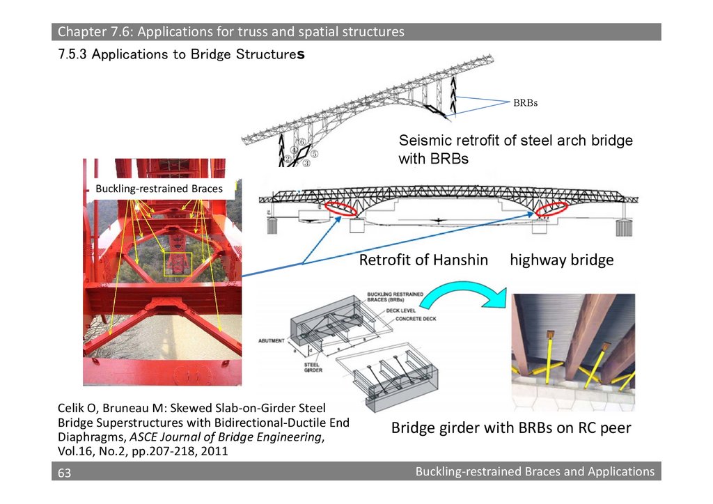
Chapter 7.6: Applications for truss and spatial structures7.5.3 Applications to Bridge Structures
BRBs
Seismic retrofit of steel arch bridge
with BRBs
Buckling‐restrained Braces
Retrofit of Hanshin
Celik O, Bruneau M: Skewed Slab‐on‐Girder Steel
Bridge Superstructures with Bidirectional‐Ductile End
Diaphragms, ASCE Journal of Bridge Engineering,
Vol.16, No.2, pp.207‐218, 2011
63
63
highway bridge
Bridge girder with BRBs on RC peer
Buckling‐restrained Braces and Applications
64.
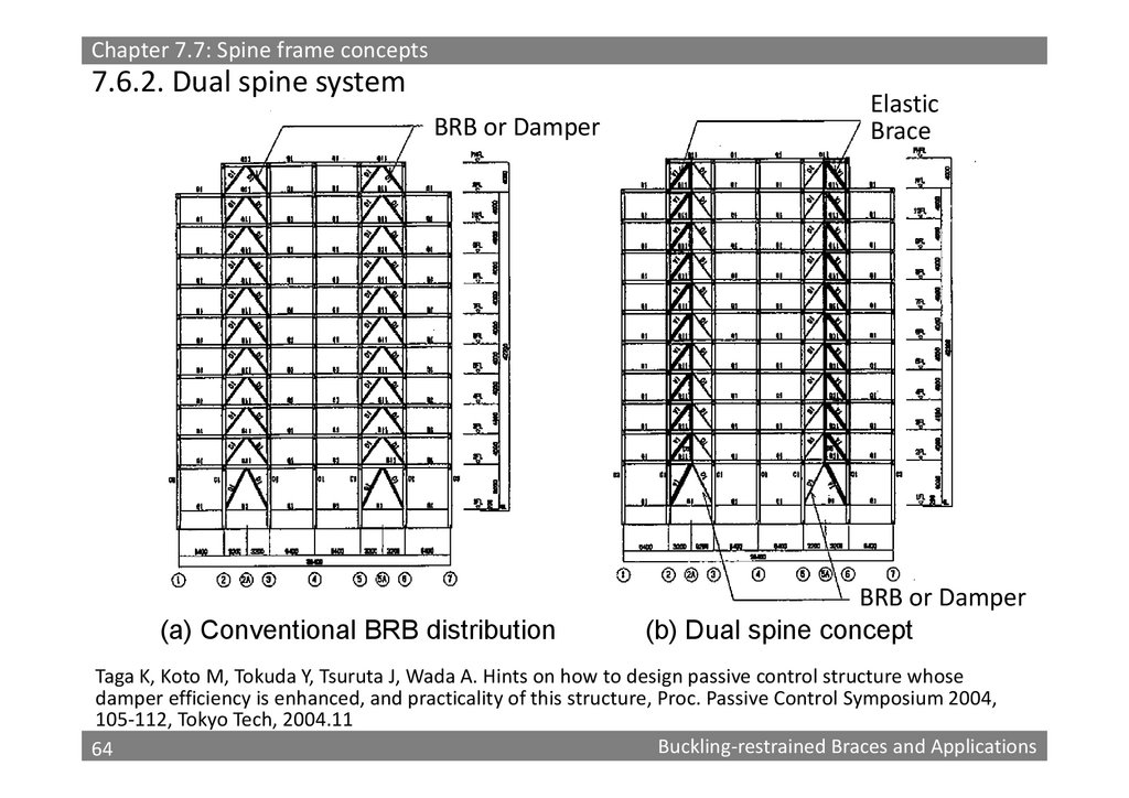
Chapter 7.7: Spine frame concepts7.6.2. Dual spine system
BRB or Damper
(a) Conventional BRB distribution
Elastic
Brace
BRB or Damper
(b) Dual spine concept
Taga K, Koto M, Tokuda Y, Tsuruta J, Wada A. Hints on how to design passive control structure whose
damper efficiency is enhanced, and practicality of this structure, Proc. Passive Control Symposium 2004,
105‐112, Tokyo Tech, 2004.11
64
Buckling‐restrained Braces and Applications
64
65.
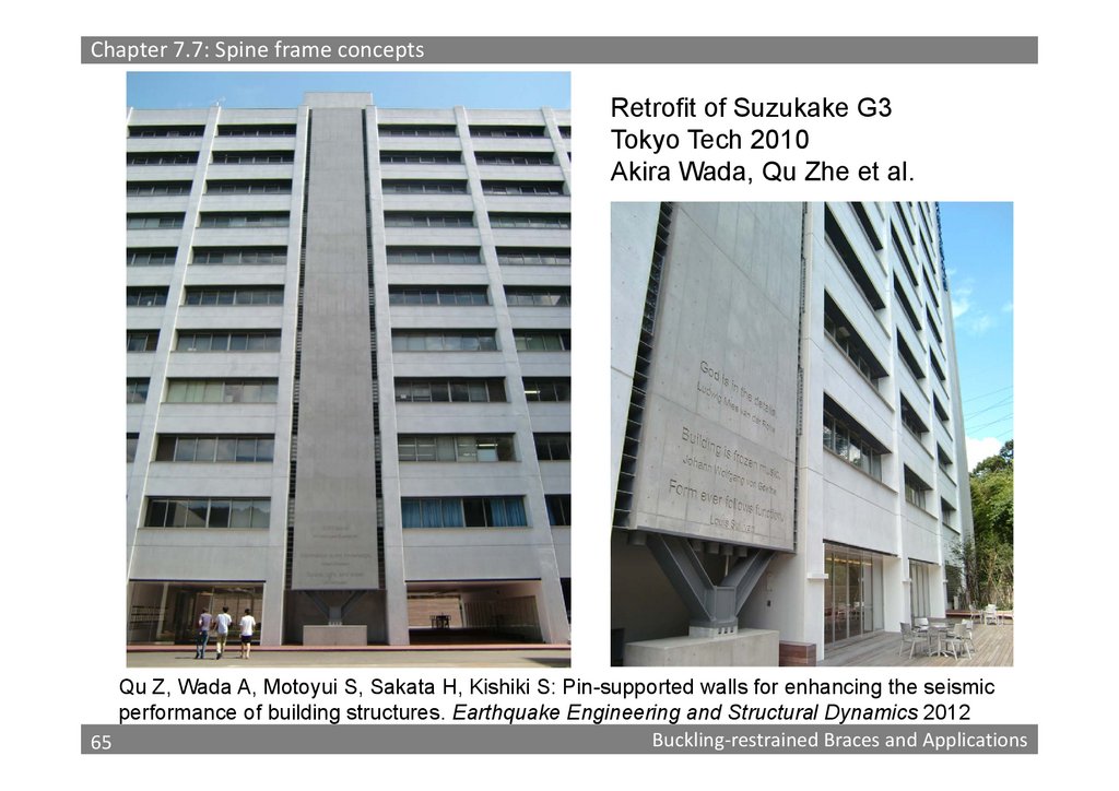
Chapter 7.7: Spine frame conceptsRetrofit of Suzukake G3
Tokyo Tech 2010
Akira Wada, Qu Zhe et al.
Qu Z, Wada A, Motoyui S, Sakata H, Kishiki S: Pin-supported walls for enhancing the seismic
performance of building structures. Earthquake Engineering and Structural Dynamics 2012
65
Buckling‐restrained Braces and Applications
65
66.
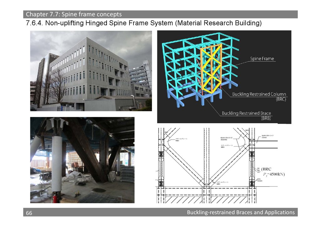
Chapter 7.7: Spine frame concepts7.6.4. Non-uplifting Hinged Spine Frame System (Material Research Building)
66
66
Buckling‐restrained Braces and Applications
67.
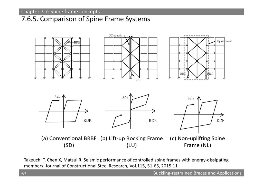
Chapter 7.7: Spine frame concepts7.6.5. Comparison of Spine Frame Systems
(a) Conventional BRBF (b) Lift‐up Rocking Frame
(SD)
(LU)
(c) Non‐uplifting Spine
Frame (NL)
Takeuchi T, Chen X, Matsui R. Seismic performance of controlled spine frames with energy‐dissipating
members, Journal of Constructional Steel Research, Vol.115, 51‐65, 2015.11
67
Buckling‐restrained Braces and Applications
67
68.
Chapter 7.7: Spine frame concepts5
4
Shear
Damper
System
0.8% rad.
(1/125)
3
2
2
5
4
Lift-up
Spine
System
1
0 0.2 0.4 0.6 0.8 1 1.2 1.4 1.6
0.8% rad.
(1/125)
2
2
0 0.2 0.4 0.6 0.8 1 1.2 1.4 1.6
5
4
BRC
BRC
0.8% rad.
(1/125)
0.03
0.06
0.09
0.12
0.15
0.05% rad.
(1/2000)
4
3
1
Non Lift-up
Spine
System
0
5
3
BRC
0.05% rad.
(1/2000)
4
3
1
PT wire
5
1
0
0.03
5
3
2
2
0.09
0.12
0.15
0.05% rad.
(1/2000)
4
3
0.06
1
1
0 0.2 0.4 0.6 0.8 1 1.2 1.4 1.6
0
0.03
0.06
0.09
0.12
0.15
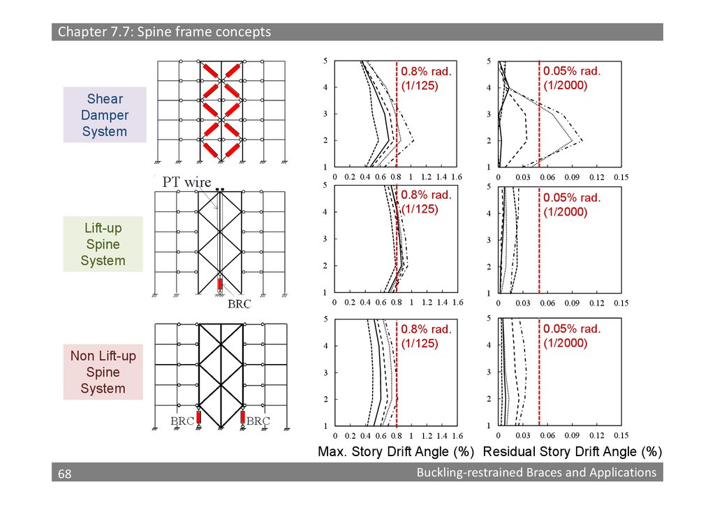
Max. Story Drift Angle (%) Residual Story Drift Angle (%)
68
68
Buckling‐restrained Braces and Applications
69.
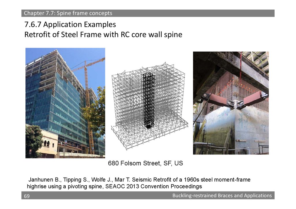
Chapter 7.7: Spine frame concepts7.6.7 Application Examples
Retrofit of Steel Frame with RC core wall spine
680 Folsom Street, SF, US
Janhunen B., Tipping S., Wolfe J., Mar T. Seismic Retrofit of a 1960s steel moment-frame
highrise using a pivoting spine, SEAOC 2013 Convention Proceedings
69
69
Buckling‐restrained Braces and Applications
70.
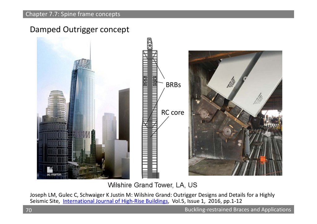
Chapter 7.7: Spine frame conceptsDamped Outrigger concept
BRBs
RC core
Wilshire Grand Tower, LA, US
Joseph LM, Gulec C, Schwaiger K Justin M: Wilshire Grand: Outrigger Designs and Details for a Highly
Seismic Site, International Journal of High‐Rise Buildings, Vol.5, Issue 1, 2016, pp.1‐12
70
Buckling‐restrained Braces and Applications
70
71.
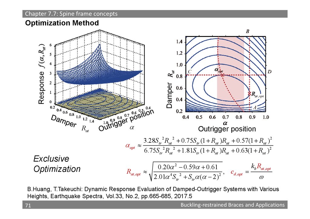
Chapter 7.7: Spine frame conceptsDamper
Response
Optimization Method
Rat
opt
Exclusive
Optimization
Outrigger position
3.28Str 2 Rat 2 0.75Str (1 Rat ) Rat 0.57(1 Rat ) 2
6.75Str 2 Rat 2 1.81Str (1 Rat ) Rat 0.63(1 Rat ) 2
Rat , opt
kb Rat , opt
0.20 2 0.59 0.61
,
c
d , opt
2.01 4 Str 2 Str ( 2) 2
B.Huang, T.Takeuchi: Dynamic Response Evaluation of Damped-Outrigger Systems with Various
Heights, Earthquake Spectra, Vol.33, No.2, pp.665-685, 2017.5
71
Buckling‐restrained Braces and Applications
71
72.
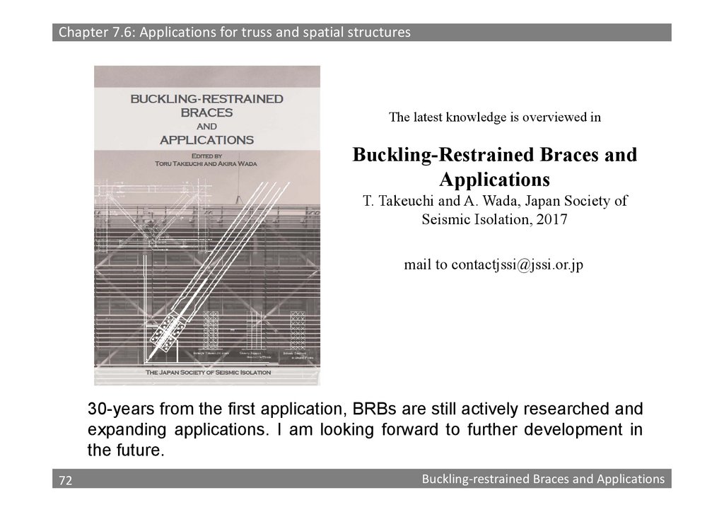
Chapter 7.6: Applications for truss and spatial structuresThe latest knowledge is overviewed in
Buckling-Restrained Braces and
Applications
T. Takeuchi and A. Wada, Japan Society of
Seismic Isolation, 2017
mail to [email protected]
30-years from the first application, BRBs are still actively researched and
expanding applications. I am looking forward to further development in
the future.
72
72
Buckling‐restrained Braces and Applications
73.
Thank you very much for your kind attention73