
 Строительство
Похожие презентации:
")


See discussions, stats, and author profiles for this publication
1.
See discussions, stats, and author profiles for this publication at: https://www.researchgate.net/publication/254303986Jet-Pacs Project: Dynamic Experimental Tests
and Numerical Results Obtained for a Steel
Frame Equipped with Hysteretic Damped...
Article in Journal of Earthquake Engineering · July 2012
DOI: 10.1080/13632469.2012.657335
CITATIONS
READS
28
83
7 authors, including:
Felice Carlo Ponzo
Antonio Di Cesare
Università degli Studi della Basilicata
Università degli Studi della Basilicata
101 PUBLICATIONS 585 CITATIONS
19 PUBLICATIONS 74 CITATIONS
SEE PROFILE
SEE PROFILE
Alfonso Vulcano
Claudio Moroni
Università della Calabria
23 PUBLICATIONS 111 CITATIONS
39 PUBLICATIONS 411 CITATIONS
SEE PROFILE
SEE PROFILE
Some of the authors of this publication are also working on these related projects:
Progetto Reluis - Coordinamento Progetto speciale Osservatorio Sismico delle Strutture e
Monitoraggio View project
All content following this page was uploaded by Fabio Mazza on 07 March 2014.
The user has requested enhancement of the downloaded file. All in-text references underlined in blue
are linked to publications on ResearchGate, letting you access and read them immediately.
2.
Journal of Earthquake Engineering, 16:662–685, 2012Copyright © A. S. Elnashai & N. N. Ambraseys
ISSN: 1363-2469 print / 1559-808X online
DOI: 10.1080/13632469.2012.657335
Downloaded by [Univ Studi Della Calabria], [Fabio Mazza] at 02:59 03 July 2012
Jet-Pacs Project: Dynamic Experimental Tests
and Numerical Results Obtained for a Steel Frame
Equipped with Hysteretic Damped Chevron Braces
FELICE CARLO PONZO1 , ANTONIO DI CESARE1 ,
DOMENICO NIGRO1 , ALFONSO VULCANO2 ,
FABIO MAZZA2 , MAURO DOLCE3 , and CLAUDIO MORONI3
1
Dipartimento di Strutture, Geotecnica, Geologia Applicata all’Ingegneria,
Università della Basilicata, Potenza, Italy
2
Dipartimento di Strutture, Università della Calabria, Rende (Cosenza), Italy
3
Dipartimento di Protezione Civile, Roma, Italy
The experimental and numerical results obtained by Research Units of the University of Basilicata
and University of Calabria for a steel frame, bare or equipped with metallic yielding hysteretic
dampers (HYDs), are compared. The shaking table tests were performed at the Structural
Laboratory of the University of Basilicata within a wide research program, named JETPACS (“Joint
Experimental Testing on Passive and semiActive Control Systems”), which involved many Research
Units working for the Research Line 7 of the ReLUIS (Italian Network of University Laboratories
of Earthquake Engineering) 2005–2008 project. The project was entirely founded by the Italian
Department of Civil Protection. The test structure is a 1/1.5 scaled two-story, single-bay, threedimensional steel frame. Four HYDs, two for each story, are inserted at the top of chevron braces
installed within the bays of two parallel plane frames along the test direction. The HYDs, constituted
of a low-carbon U-shaped steel plate, were designed with the performance objective of limiting the
inter-story drifts so that the frame yielding is prevented. Two design solutions are considered, assuming the same stiffness of the chevron braces with HYDs, but different values of both ductility demand
and yield strength of the HYDs. Seven recorded accelerograms matching on average the response
spectrum of Eurocode 8 for a high-risk seismic region and a medium subsoil class are considered as
seismic input. The experimental results are compared with the numerical ones obtained considering
an elastic-linear law for the chevron braces (in tension and compression), providing that the buckling
be prevented, and the Bouc-Wen model to simulate the response of HYDs.
Keywords Shaking Table; Experimental Results; Nonlinear Dynamic Analysis; Framed Structures;
Metallic Hysteretic Dampers; Performance-Based Design
1. Introduction
Traditional retro tting techniques for framed structures are based on widespread strengthening of the structure and/or on the introduction of additional, very stiff, structural
members. In recent decades, innovative strategies for the passive control of structures
were studied and experimented, such as those based on the insertion of damped braces,
connecting two consecutive stories of the building and incorporating suitable devices,
Received 20 August 2011; accepted 10 January 2012.
Address correspondence to Fabio Mazza, Dipartimento di Strutture, Università della Calabria, Rende
(Cosenza), Italy. E-mail: [email protected]
662
3.
Downloaded by [Univ Studi Della Calabria], [Fabio Mazza] at 02:59 03 July 2012Jet-Pacs Project
663
purposely designed to dissipate a large amount of energy (e.g., see Soong and Dargush,
1997; Christopoulos and Filiatrault, 2006). The application to existing buildings of the
energy dissipation strategy is rapidly increasing throughout the world. Several types of
both passive and semi-active energy dissipating systems are in use today and many new
solutions are continuously being proposed and investigated.
The dissipative bracing systems which were proposed differ for the particular arrangement of the braces and/or for the features of the dissipative device (in particular, by the
way of dissipating energy). In the present work, the attention is focused on metallic yielding hysteretic dampers (HYDs), which are characterized by a stable hysteretic behavior
independent on temperature and velocity of motion; their activation happens when preset stress levels are reached or overcome. These devices are generally manufactured from
traditional materials and require little maintenance, representing a low cost and reliable
solution for energy dissipation. The rst idea of using hysteretic dampers for earthquake
resistant structures was given by Kelly et al. [1972]. Afterwards, many HYDs were proposed in literature (e.g., see Martìnez-Rueda, 2002), but in the following only some of
the most relevant worldwide applications are brie y described. The device proposed by
Ciampi [1989] consists of an inner steel frame, geometrically similar to the frame mesh
into which the braces are inserted, with a variable cross-section to provide uniform bending plasticization. Later, other damped steel-bracing systems where proposed and tested at
the University of California at Berkeley. One of the most popular is the ADAS (AddedDamping-Added-Stiffness) damper [Whittaker et al., 1991], having X-shaped steel plates
clamped at both ends; the tapered section of the plates allowed a uniform exural yielding
along the height of the device. Tsai et al. [1993] developed a variation of the ADAS system (TADAS, Triangular-Added-Damping-Added-Stiffness) using triangular steel plates,
where the effect of the gravity loads is removed from the device by using slotted holes in
the connection details. Moreover, E-shaped and C-shaped HYDs, whose geometry allowed
an almost uniform plastic deformation, were proposed by Ciampi [1993].
A widespread diffusion of these techniques has not yet been achieved, mainly due
to the lack of extensive experimental information allowing for the adoption of less
conservative design rules. For this reason, an extensive dynamic experimental testing program, named JETPACS (Joint Experimental Testing on Passive and semiActive Control
Systems), was carried out at the Structural Laboratory of the University of Basilicata
[Dolce et al., 2008], within the research line No. 7 of the ReLUIS 2005–2008 executive project. The JETPACS Project has been supported by several partners from different
Italian Universities, which in turn have developed or studied a number of energy dissipation devices based on different materials and/or principles. The tests have been carried out
on a 1/1.5 scaled structural model derived from a two-story, one-bay, three-dimensional
steel frame, prototype building. During dynamic testing, a total of seven different passive
or semi-active energy dissipating devices based on currently available technologies (i.e.,
hysteretic and viscous damping) or innovative systems (i.e., shape-memory-alloy wires,
magneto-rheological uids) were used. In particular, a new type of HYD manufactured
by T.I.S. S.p.A. has been studied by the Research Units of the University of Basilicata
(UNIBAS) and University of Calabria (UNICAL), and presented in this work. Firstly, an
overview of the experimental model set up and the detailed aspects of the experimental
model, test apparatus, and sensor set up are presented. Afterwards, the ef ciency of the
proposed HYD in dissipating input energy and in reducing the seismic response of the
structural model under moderate and strong earthquakes is investigated, in order to obtain
experimental data useful for developing a design procedure. To this end, during the tests,
the structural model was subjected to seven recorded accelerograms selected from ReLUIS
database [Iervolino et al., 2008], matching on average the response spectrum of Eurocode 8
4.
Downloaded by [Univ Studi Della Calabria], [Fabio Mazza] at 02:59 03 July 2012664
F. C. Ponzo et al.
[EC8, 2003] for a high-risk seismic region and a medium subsoil class. The seismic intensity was progressively increased, up to the attainment of the performance objective adopted
in the design.
The increasing number of numerical studies on a large number of dissipative braces
and the analysis of real applications have not been followed by a parallel improvement of
related codes and guidelines, as in the case of other innovative techniques (e.g., seismic
isolation). In Europe, new seismic codes only implicitly allow for the use of these devices
(i.e., EC8, 2003; NTC, 2008), while very few codes in the world provide for simpli ed
criteria for the design (e.g., FEMA-ASCE 356, 2000). For a widespread application of the
dissipative braces, practical design procedures are needed. According to the philosophy of
the Performance-Based Earthquake Design [Bertero, 2002], a performance design objective is obtained coupling a performance level (e.g., fully operational, operational, life safe,
or near collapse) with a speci c level of ground motion (e.g., frequent, occasional, rare, or
very rare). Speci cally, two alternative approaches can be followed: (a) the Force-Based
Design (FBD) approach combined with required deformation target veri cation (e.g., see
Kim et al., 2003; Ponzo et al., 2007b; referring to HYDs); (b) the Direct DisplacementBased Design (DDBD) approach, in which the design starts from a target deformation (e.g.,
see Kim and Choi, 2006; Mazza and Vulcano, 2008; referring to HYDs). A FBD procedure,
aiming to proportion steel braces equipped with HYDs, in order to prevent damage to structural members, is presented in this article. Two design solutions are considered, assuming
the same stiffness of the chevron braces with HYDs, but different values of both ductility
demand and yield strength of the HYDs. The performance objective is expressed in terms
of a threshold value of the maximum inter-story drift, lower than the yield inter-story drifts
of the structure, which is supposed to respond within its elastic range during the shaking
table tests. A further goal is to verify the reliability of the simpli ed method used to design
the mechanical characteristic of the damping devices. To this end, the numerical results of
nonlinear dynamic analysis carried out on the steel frame, bare or equipped with HYDs,
are also reported and compared with the experimental results.
2. Experimental and Numerical Models
The experimental 1/1.5-scaled model for dynamic tests has been designed starting from
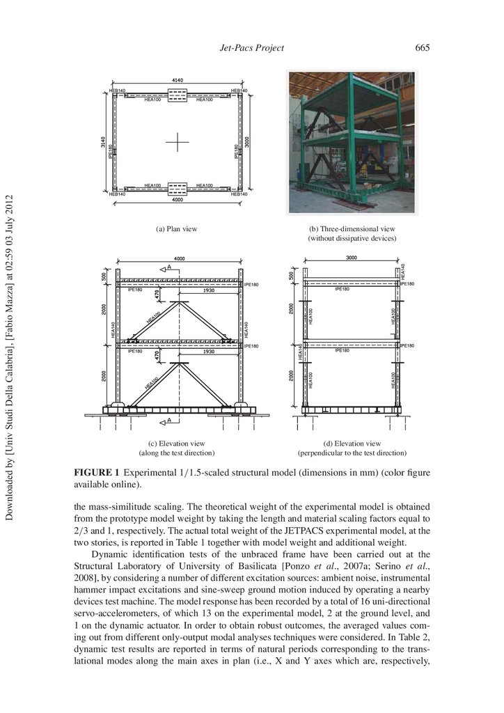
a residential housing steel building prototype. Figure 1 shows a photographic view and
the general layout of the experimental model. The test structure is a two-story, threedimensional steel frame, with plan dimensions of 4 m by 3 m and inter-story height equal to
2 m. The two oors are made of HI-bond corrugated steel sheets, with upper 100 mm-thick
reinforced concrete slab, connected to the primary beams. Primary and secondary beams
have equal steel cross-section (IPE 180) for the two stories and the columns have constant
cross-section (HEB 140) along the model height. Beam-to-column joints are welded and
stiffened by horizontal plates crossing the panel zones of columns. The rigid diaphragm
condition at the base of the experimental model is achieved by four steel beams (HEB
220) and two horizontal V-inverted braces (HEA 160), connected with the shaking table
system of the test apparatus. Finally, four vertical V-inverted braces (HEA 100), two for
each story, are inserted within the bays of two parallel frames along the test direction.
The experimental model is realized using Fe360 grade steel, having Young modulus E= 206000 N/mm2 , yielding strength fy = 235 N/mm2 and ultimate strength fu =
360 N/mm2 . The gravity loads used in the design are represented by dead- and live-loads,
respectively equal to 3.25 kN/m2 and 2 kN/m2 . Four additional concrete masses have been
symmetrically placed on each oor slab (see Fig. 2), to take into account the non-structural
dead loads and a proper amount (30%) of live loads, as well as the contribution due to
5.
Downloaded by [Univ Studi Della Calabria], [Fabio Mazza] at 02:59 03 July 2012Jet-Pacs Project
665
(a) Plan view
(b) Three-dimensional view
(without dissipative devices)
(c) Elevation view
(along the test direction)
(d) Elevation view
(perpendicular to the test direction)
FIGURE 1 Experimental 1/1.5-scaled structural model (dimensions in mm) (color gure
available online).
the mass-similitude scaling. The theoretical weight of the experimental model is obtained
from the prototype model weight by taking the length and material scaling factors equal to
2/3 and 1, respectively. The actual total weight of the JETPACS experimental model, at the
two stories, is reported in Table 1 together with model weight and additional weight.
Dynamic identi cation tests of the unbraced frame have been carried out at the
Structural Laboratory of University of Basilicata [Ponzo et al., 2007a; Serino et al.,
2008], by considering a number of different excitation sources: ambient noise, instrumental
hammer impact excitations and sine-sweep ground motion induced by operating a nearby
devices test machine. The model response has been recorded by a total of 16 uni-directional
servo-accelerometers, of which 13 on the experimental model, 2 at the ground level, and
1 on the dynamic actuator. In order to obtain robust outcomes, the averaged values coming out from different only-output modal analyses techniques were considered. In Table 2,
dynamic test results are reported in terms of natural periods corresponding to the translational modes along the main axes in plan (i.e., X and Y axes which are, respectively,
6.
666F. C. Ponzo et al.
Dynamic
Actuator
profile
rail guide
Downloaded by [Univ Studi Della Calabria], [Fabio Mazza] at 02:59 03 July 2012
Reaction
Wall
(a) Plan layout
Reaction
Wall
(b) Three-dimensional view
(with dissipative devices)
Additional Masses
Additional Masses
energy
dissipation
devices
Dynamic
Actuator
profile
rail guide
(c) Elevation layout
(along the test direction)
(c) Elevation layout
(perpendicular to the test direction)
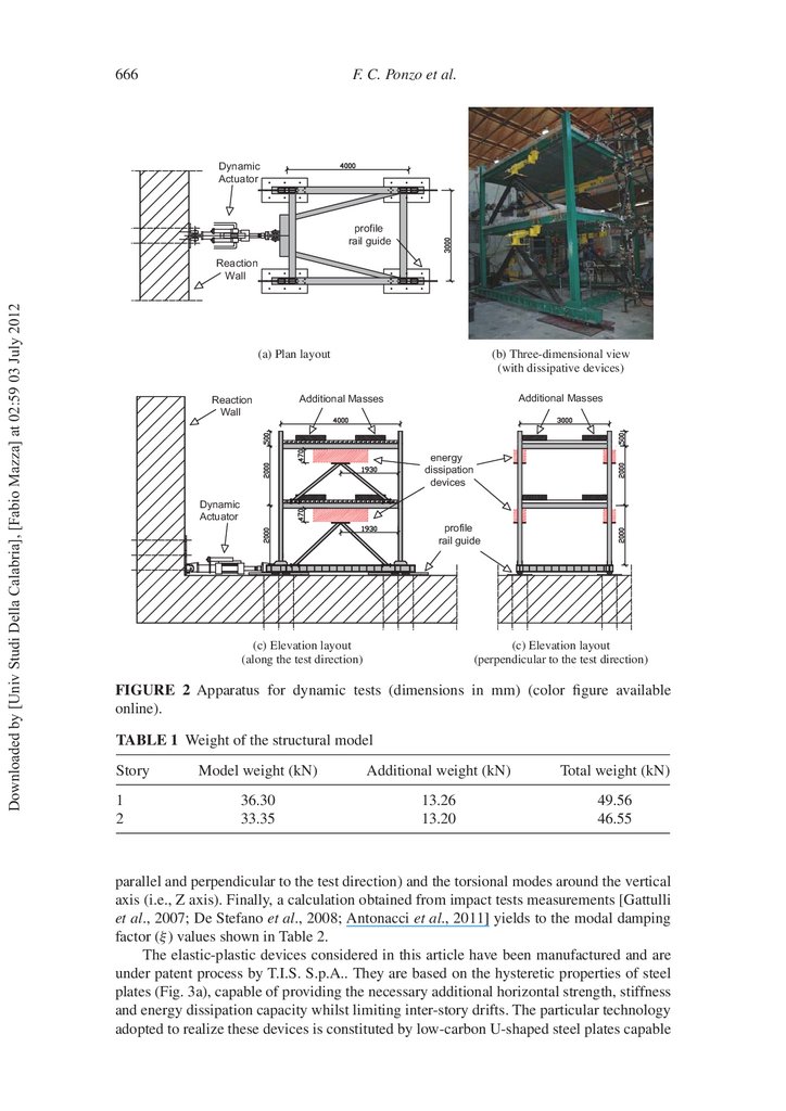
FIGURE 2 Apparatus for dynamic tests (dimensions in mm) (color gure available
online).
TABLE 1 Weight of the structural model
Story
1
2
Model weight (kN)
Additional weight (kN)
Total weight (kN)
36.30
33.35
13.26
13.20
49.56
46.55
parallel and perpendicular to the test direction) and the torsional modes around the vertical
axis (i.e., Z axis). Finally, a calculation obtained from impact tests measurements [Gattulli
et al., 2007; De Stefano et al., 2008; Antonacci et al., 2011] yields to the modal damping
factor (ξ ) values shown in Table 2.
The elastic-plastic devices considered in this article have been manufactured and are
under patent process by T.I.S. S.p.A.. They are based on the hysteretic properties of steel
plates (Fig. 3a), capable of providing the necessary additional horizontal strength, stiffness
and energy dissipation capacity whilst limiting inter-story drifts. The particular technology
adopted to realize these devices is constituted by low-carbon U-shaped steel plates capable
7.
Jet-Pacs Project667
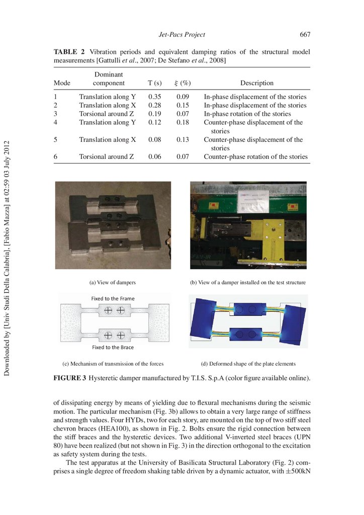
TABLE 2 Vibration periods and equivalent damping ratios of the structural model
measurements [Gattulli et al., 2007; De Stefano et al., 2008]
Dominant
component
T (s)
ξ (%)
Description
1
2
3
4
Translation along Y
Translation along X
Torsional around Z
Translation along Y
0.35
0.28
0.19
0.12
0.09
0.15
0.07
0.18
5
Translation along X
0.08
0.13
6
Torsional around Z
0.06
0.07
In-phase displacement of the stories
In-phase displacement of the stories
In-phase rotation of the stories
Counter-phase displacement of the
stories
Counter-phase displacement of the
stories
Counter-phase rotation of the stories
Downloaded by [Univ Studi Della Calabria], [Fabio Mazza] at 02:59 03 July 2012
Mode
(a) View of dampers
(b) View of a damper installed on the test structure
Fixed to the Frame
Fixed to the Brace
(c) Mechanism of transmission of the forces
(d) Deformed shape of the plate elements
FIGURE 3 Hysteretic damper manufactured by T.I.S. S.p.A (color gure available online).
of dissipating energy by means of yielding due to exural mechanisms during the seismic
motion. The particular mechanism (Fig. 3b) allows to obtain a very large range of stiffness
and strength values. Four HYDs, two for each story, are mounted on the top of two stiff steel
chevron braces (HEA100), as shown in Fig. 2. Bolts ensure the rigid connection between
the stiff braces and the hysteretic devices. Two additional V-inverted steel braces (UPN
80) have been realized (but not shown in Fig. 3) in the direction orthogonal to the excitation
as safety system during the tests.
The test apparatus at the University of Basilicata Structural Laboratory (Fig. 2) comprises a single degree of freedom shaking table driven by a dynamic actuator, with ±500kN
8.
668F. C. Ponzo et al.
Downloaded by [Univ Studi Della Calabria], [Fabio Mazza] at 02:59 03 July 2012
(a) SKF profile rail guide
(b) Model base
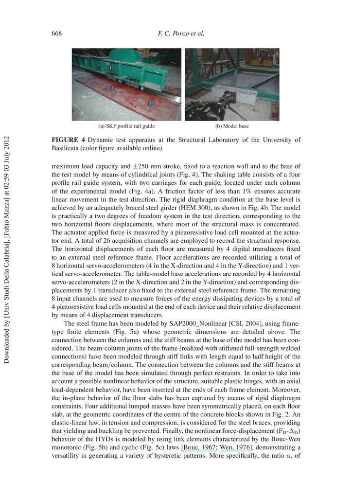
FIGURE 4 Dynamic test apparatus at the Structural Laboratory of the University of
Basilicata (color gure available online).
maximum load capacity and ±250 mm stroke, xed to a reaction wall and to the base of
the test model by means of cylindrical joints (Fig. 4). The shaking table consists of a four
pro le rail guide system, with two carriages for each guide, located under each column
of the experimental model (Fig. 4a). A friction factor of less than 1% ensures accurate
linear movement in the test direction. The rigid diaphragm condition at the base level is
achieved by an adequately braced steel girder (HEM 300), as shown in Fig. 4b. The model
is practically a two degrees of freedom system in the test direction, corresponding to the
two horizontal oors displacements, where most of the structural mass is concentrated.
The actuator applied force is measured by a piezoresistive load cell mounted at the actuator end. A total of 26 acquisition channels are employed to record the structural response.
The horizontal displacements of each oor are measured by 4 digital transducers xed
to an external steel reference frame. Floor accelerations are recorded utilizing a total of
8 horizontal servo-accelerometers (4 in the X-direction and 4 in the Y-direction) and 1 vertical servo-accelerometer. The table-model base accelerations are recorded by 4 horizontal
servo-accelerometers (2 in the X-direction and 2 in the Y-direction) and corresponding displacements by 1 transducer also xed to the external steel reference frame. The remaining
8 input channels are used to measure forces of the energy dissipating devices by a total of
4 piezoresistive load cells mounted at the end of each device and their relative displacement
by means of 4 displacement transducers.
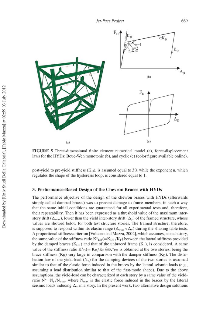
The steel frame has been modeled by SAP2000_Nonlinear [CSI, 2004], using frametype nite elements (Fig. 5a) whose geometric dimensions are detailed above. The
connection between the columns and the stiff beams at the base of the model has been considered. The beam-column joints of the frame (realized with stiffened full-strength welded
connections) have been modeled through stiff links with length equal to half height of the
corresponding beam/column. The connection between the columns and the stiff beams at
the base of the model has been simulated through perfect restraints. In order to take into
account a possible nonlinear behavior of the structure, suitable plastic hinges, with an axial
load-dependent behavior, have been inserted at the ends of each frame element. Moreover,
the in-plane behavior of the oor slabs has been captured by means of rigid diaphragm
constraints. Four additional lumped masses have been symmetrically placed, on each oor
slab, at the geometric coordinates of the centre of the concrete blocks shown in Fig. 2. An
elastic-linear law, in tension and compression, is considered for the steel braces, providing
that yielding and buckling be prevented. Finally, the nonlinear force-displacement (FD - D )
behavior of the HYDs is modeled by using link elements characterized by the Bouc-Wen
monotonic (Fig. 5b) and cyclic (Fig. 5c) laws [Bouc, 1967; Wen, 1976], demonstrating a
versatility in generating a variety of hysteretic patterns. More speci cally, the ratio α, of
9.
Jet-Pacs Project669
Downloaded by [Univ Studi Della Calabria], [Fabio Mazza] at 02:59 03 July 2012
(b)
(a)
(c)
FIGURE 5 Three-dimensional nite element numerical model (a), force-displacement
laws for the HYDs: Bouc-Wen monotonic (b), and cyclic (c) (color gure available online).
post-yield to pre-yield stiffness (KD ), is assumed equal to 3% while the exponent n, which
regulates the shape of the hysteresis loop, is considered equal to 1.
3. Performance-Based Design of the Chevron Braces with HYDs
The performance objective of the design of the chevron braces with HYDs (afterwards
simply called damped braces) was to prevent damage to frame members, in such a way
that the same initial conditions are guaranteed for all experimental tests and, therefore,
their repeatability. Then it has been expressed as a threshold value of the maximum interstory drift ( max ), lower than the yield inter-story drift ( y ) of the framed structure, whose
values are showed below for both test structure stories. The framed structure, therefore,
is supposed to respond within its elastic range ( max < y ) during the shaking table tests.
A proportional stiffness criterion [Vulcano and Mazza, 2002], which assumes, at each story,
the same value of the stiffness ratio K∗ DB (=KDB /KF ) between the lateral stiffness provided
by the damped braces (KDB ) and that of the unbraced frame (KF ), is considered. A same
value of the stiffness ratio K∗ D (= KD /KF )∼
=K∗ DB is obtained at the two stories, being the
brace stiffness (KB ) very large in comparison with the damper stiffness (KD ). The distribution law of the yield-load (Ny ) for the damping devices of the two stories is assumed
similar to that of the elastic force induced in the braces by the lateral seismic loads (e.g.,
assuming a load distribution similar to that of the rst-mode shape). Due to the above
assumptions, the yield-load can be characterized at each story by a same value of the yieldratio N∗ =Ny /Nmax , where Nmax is the elastic force induced in the braces by the lateral
seismic loads inducing y in a story. In the present work, two alternative design solutions
10.
670F. C. Ponzo et al.
STEP 1: Preliminary evaluation of
(KF,eq , FF,eq , μF) of the bare frame
through a NLSA
modify μD
Downloaded by [Univ Studi Della Calabria], [Fabio Mazza] at 02:59 03 July 2012
STEP 2: Definition of the equivalent
dissipative bracing system
(KDB,eq , FDB,eq , μD) considering a
SDOF system
STEP 3: Distribution of the characteristics
of HYDs (FDBs,i , KDBs,i , μD) along
the structure height
NO
STEP 4: NTHA on the
damped braced frame
Δmax ≤ Δlim
YES
END
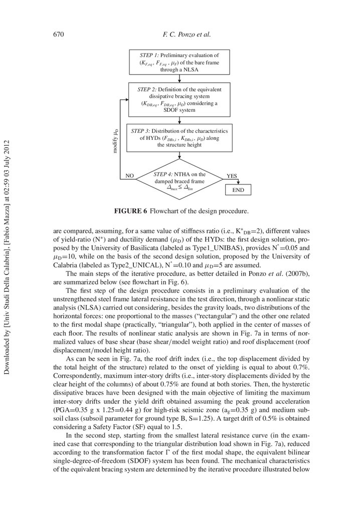
FIGURE 6 Flowchart of the design procedure.
are compared, assuming, for a same value of stiffness ratio (i.e., K∗ DB =2), different values
of yield-ratio (N∗ ) and ductility demand (μD ) of the HYDs: the rst design solution, pro∗
posed by the University of Basilicata (labeled as Type1_UNIBAS), provides N =0.05 and
μD =10, while on the basis of the second design solution, proposed by the University of
∗
Calabria (labeled as Type2_UNICAL), N =0.10 and μD =5 are assumed.
The main steps of the iterative procedure, as better detailed in Ponzo et al. (2007b),
are summarized below (see owchart in Fig. 6).
The rst step of the design procedure consists in a preliminary evaluation of the
unstrengthened steel frame lateral resistance in the test direction, through a nonlinear static
analysis (NLSA) carried out considering, besides the gravity loads, two distributions of the
horizontal forces: one proportional to the masses (“rectangular”) and the other one related
to the rst modal shape (practically, “triangular”), both applied in the center of masses of
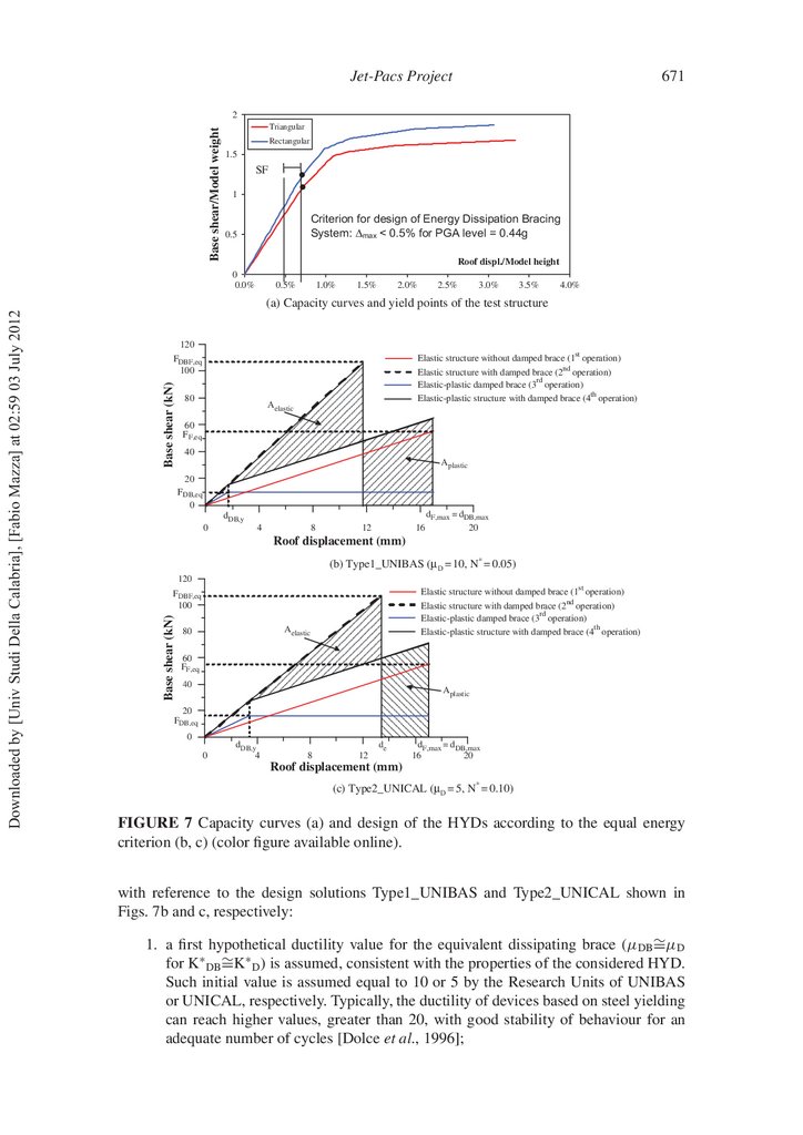
each oor. The results of nonlinear static analysis are shown in Fig. 7a in terms of normalized values of base shear (base shear/model weight ratio) and roof displacement (roof
displacement/model height ratio).
As can be seen in Fig. 7a, the roof drift index (i.e., the top displacement divided by
the total height of the structure) related to the onset of yielding is equal to about 0.7%.
Correspondently, maximum inter-story drifts (i.e., inter-story displacements divided by the
clear height of the columns) of about 0.75% are found at both stories. Then, the hysteretic
dissipative braces have been designed with the main objective of limiting the maximum
inter-story drifts under the yield drift obtained assuming the peak ground acceleration
(PGA=0.35 g x 1.25=0.44 g) for high-risk seismic zone (ag =0.35 g) and medium subsoil class (subsoil parameter for ground type B, S=1.25). A target drift of 0.5% is obtained
considering a Safety Factor (SF) equal to 1.5.
In the second step, starting from the smallest lateral resistance curve (in the examined case that corresponding to the triangular distribution load shown in Fig. 7a), reduced
according to the transformation factor of the rst modal shape, the equivalent bilinear
single-degree-of-freedom (SDOF) system has been found. The mechanical characteristics
of the equivalent bracing system are determined by the iterative procedure illustrated below
11.
Jet-Pacs Project671
Base shear/Model weight
2
Triangular
Rectangular
1.5
SF
1
Criterion for design of Energy Dissipation Bracing
System: Δmax < 0.5% for PGA level = 0.44g
0.5
Roof displ./Model height
0.5%
1.0%
1.5%
2.0%
2.5%
3.0%
3.5%
4.0%
(a) Capacity curves and yield points of the test structure
Base shear (kN)
120
FDBF,eq
100
st
Elastic structure without damped brace (1 operation)
nd
80
Elastic structure with damped brace (2 operation)
rd
Elastic-plastic damped brace (3 operation)
th
Elastic-plastic structure with damped brace (4 operation)
Aelastic
60
F F,eq
40
Aplastic
20
F DB,eq
0
dDB,y
0
4
8
12
16
dF,max = dDB,max
20
Roof displacement (mm)
(b) Type1_UNIBAS (μD = 10, N* = 0.05)
120
st
Elastic structure without damped brace (1 operation)
FDBF,eq
100
Base shear (kN)
Downloaded by [Univ Studi Della Calabria], [Fabio Mazza] at 02:59 03 July 2012
0
0.0%
nd
Elastic structure with damped brace (2 operation)
rd
Elastic-plastic damped brace (3 operation)
th
Elastic-plastic structure with damped brace (4 operation)
Aelastic
80
60
FF,eq
40
Aplastic
20
FDB,eq
0
0
dDB,y
4
8
12
de
dF,max = dDB,max
16
20
Roof displacement (mm)
(c) Type2_UNICAL (μD = 5, N* = 0.10)
FIGURE 7 Capacity curves (a) and design of the HYDs according to the equal energy
criterion (b, c) (color gure available online).
with reference to the design solutions Type1_UNIBAS and Type2_UNICAL shown in
Figs. 7b and c, respectively:
1. a rst hypothetical ductility value for the equivalent dissipating brace (μDB ∼
=μD
for K∗ DB ∼
=K∗ D ) is assumed, consistent with the properties of the considered HYD.
Such initial value is assumed equal to 10 or 5 by the Research Units of UNIBAS
or UNICAL, respectively. Typically, the ductility of devices based on steel yielding
can reach higher values, greater than 20, with good stability of behaviour for an
adequate number of cycles [Dolce et al., 1996];
12.
Downloaded by [Univ Studi Della Calabria], [Fabio Mazza] at 02:59 03 July 2012672
F. C. Ponzo et al.
2. the seismic force at j-th step (FDBF,eq (j) ) for the equivalent elastic singledegree-of-freedom (SDOF) system is evaluated, as a function of the global dynamic
characteristics of the braced structure and of the design earthquake; the initial value
of the design force (FDBF,eq (0) ) is obtained multiplying the equivalent mass of the
model (m∗ ) by the pseudo-acceleration Se (T∗ ) derived from the elastic response
spectrum for the equivalent period of the structure without damped braces (T∗ F );
3. the yield displacement of the equivalent bilinear brace (dDB,y ) is determined, starting from the available ductility μDB xed at step 1 and imposing that the maximum
displacement of the equivalent damped brace (dDB,max ) is equal to the elastic target
displacement of the equivalent unbraced structure (dF,max ). The yielding force of
the equivalent damped brace (FDB,eq ) is determined by means of the “equal energy
criterion,” considering the equivalent elastic SDOF system and the equivalent
elastic-plastic SDOF system of the damped braced structure.
By step 2 it is possible to calculate the yield force of the equivalent elastic-plastic
brace at j-th step (FDB,eq (j) ), which allows one to determine the stiffness of the equivalent
damped brace (KDB,eq (j) ), the vibration period of the damped braced frame (T∗ DBF,j ), and a
new value of the seismic elastic force (FDBF,eq (j+1) ). The procedure converges to solution
when the difference between the elastic seismic forces evaluated in two consecutive loops
is less than an acceptable tolerance.
The mechanical characteristics of the single device along the height of the model are
evaluated in the third step. The stiffness distribution of the equivalent elastic-plastic device
(representing the story devices as a whole) is made under the hypothesis that the ratio
between the equivalent bracing stiffness (KDB,i ) and the stiffness of the unbraced structure
(KF,i ), at the i-th story, is equal to the ratio between the stiffness of the equivalent damped
brace (KDB,eq ) and the stiffness of the equivalent elastic system of the unbraced structure
(KF,eq ):
KDB,eq
KDB,i
=
KF,i
KF,eq
→
KDB,i = KF,i
KDB,eq
KF,eq
.
(3.1a,b)
With regard to the strength distribution at the i-th story, the ratio between the equivalent
bracing strength (FDB,i ) and the strength of the unbraced structure (FF,i ) is assumed equal
to the ratio between the strength of the equivalent damped brace (FDB,eq ) and strength of
the equivalent elastic system of the primary structure (FF,eq ) corresponding to the yield
displacement (dF,y ):
FDB,eq
FDB,i
=
FF,i
FF,eq
→
FDB,i = FF,i
FDB,eq
FF,eq
.
(3.2a,b)
The distribution laws of stiffness Eq. (3.1a,b) and strength Eq. (3.2a,b) along the building height have been obtained combining, respectively, the hypothesis of a constant value
of the stiffness ratio K∗ DB (=KDB /KF ) and yield-ratio N∗ (=Ny /Nmax ), at each story, with
the assumption of an equivalent single-degree-of-freedom system representing the actual
damped structure. The stiffness KF,i and strength Fy,i of i-th story of the primary structure
are determined through a linear static analysis. Stiffness and strength of the equivalent i-th
story device are shared between the single devices (KDBs,i and FDBs,i ) for the two-story
devices.
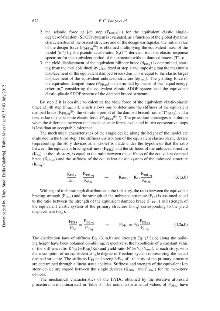
The mechanical characteristics of the HYDs, obtained by the iterative aforesaid
procedure, are summarized in Table 3. The actual experimental values of FDBs,i have
13.
Jet-Pacs Project673
TABLE 3 Mechanical characteristics of the hysteretic damped braces
FDBs,i (kN)
Design solutions
Level
Experimental
values
Design
values
Experimental
values
Design
values
μD,i
Type1_UNIBAS
I
II
I
II
7.5
4.5
10.0
7.0
5.0
3.5
8.0
5.5
7.0
4.0
7.0
4.0
7.0
4.0
7.0
4.0
10
10
5
5
Type2_UNICAL
Downloaded by [Univ Studi Della Calabria], [Fabio Mazza] at 02:59 03 July 2012
KDBs,i (kN/mm)
been assumed higher than the design values in order to take into account the industrial
standardization in the production of the devices.
The design procedure considered to evaluate the mechanical characteristics of the
devices maximizes the value of energy dissipated by the device with an acceptable value
of ductility demand and provides a lower bound over which the maximum acceleration and drift become constants [Ponzo and Di Cesare, 2009]. The effectivness of the
proposed design procedure has been veri ed only with reference to cases in which the structural response is not severely affected by higher mode effects due to high-rise buildings.
According to the proportional stiffness criterion, it can be reasonably assumed that a mode
shape of the primary frame remains practically the same even after the insertion of damped
braces. Therefore, this design criterion is preferable in the case of a retro tting, because
the stress distribution of the framed structure remains practically unchanged. Moreover, an
improvement of the procedure for in-plan irregular buildings has been recently proposed
by Di Cesare et al. [2011].
4. Seismic Input
To evaluate the effects induced by the damped braces on the seismic response of the test
structure, many experimental and numerical nonlinear dynamic analyses have been carried
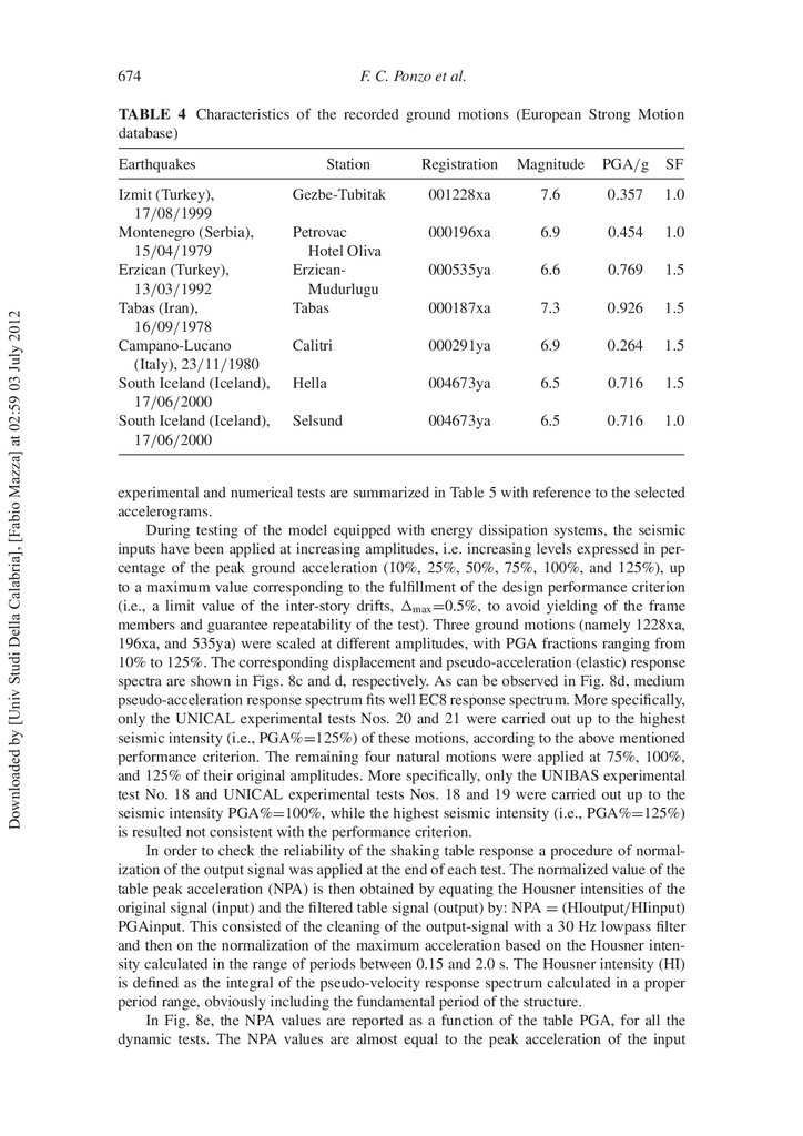
out considering real ground motions. Speci cally, seven recorded accelerograms, available in the European Strong Motions database (www.reluis.it) and considered in ReLUIS
project, were selected taking into account the assumptions made, with regard to seismic
intensity (seismic zone 1, ag =0.35 g) and ground type (subsoil class B, subsoil parameter
S=1.25), in the design of the experimental model (i.e., PGA=1.25x0.35 g=0.44 g). The
corresponding main data are reported in Table 4, i.e., station, identi cation number of the
registration, magnitude, peak ground acceleration (PGA) in the horizontal direction, and
scale factor (SF) suggested by Iervolino et al. [2008].
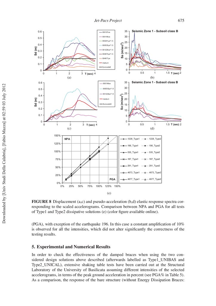
The pseudo-acceleration (elastic) response spectra of the seven accelerograms match,
on average, EC8 spectrum for a subsoil class B, in the range of periods 0.05–2 s. The displacement and pseudo-acceleration (elastic) response spectra of the seven accelerograms
are shown in Figs. 8a and b, respectively, together with the corresponding medium spectrum and EC8 spectrum, assuming an equivalent viscous damping ratio ξ =5%. To ensure
consistency with the scale of the model, all accelerograms are then scaled down in time by
the factor (1.5)1/2 .
The experimental program was developed in 18 and 21 seismic tests, respectively, for
UNIBAS and UNICAL research units. The intensities of the ground motions (expressed
as percentage of the peak ground accelerations: PGA%) which were assumed for the
14.
674F. C. Ponzo et al.
TABLE 4 Characteristics of the recorded ground motions (European Strong Motion
database)
Downloaded by [Univ Studi Della Calabria], [Fabio Mazza] at 02:59 03 July 2012
Earthquakes
Izmit (Turkey),
17/08/1999
Montenegro (Serbia),
15/04/1979
Erzican (Turkey),
13/03/1992
Tabas (Iran),
16/09/1978
Campano-Lucano
(Italy), 23/11/1980
South Iceland (Iceland),
17/06/2000
South Iceland (Iceland),
17/06/2000
Station
Registration
Magnitude
PGA/g
SF
Gezbe-Tubitak
001228xa
7.6
0.357
1.0
Petrovac
Hotel Oliva
ErzicanMudurlugu
Tabas
000196xa
6.9
0.454
1.0
000535ya
6.6
0.769
1.5
000187xa
7.3
0.926
1.5
Calitri
000291ya
6.9
0.264
1.5
Hella
004673ya
6.5
0.716
1.5
Selsund
004673ya
6.5
0.716
1.0
experimental and numerical tests are summarized in Table 5 with reference to the selected
accelerograms.
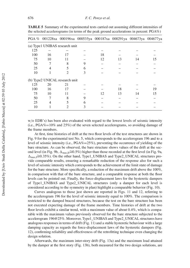
During testing of the model equipped with energy dissipation systems, the seismic
inputs have been applied at increasing amplitudes, i.e. increasing levels expressed in percentage of the peak ground acceleration (10%, 25%, 50%, 75%, 100%, and 125%), up
to a maximum value corresponding to the ful llment of the design performance criterion
(i.e., a limit value of the inter-story drifts, max =0.5%, to avoid yielding of the frame
members and guarantee repeatability of the test). Three ground motions (namely 1228xa,
196xa, and 535ya) were scaled at different amplitudes, with PGA fractions ranging from
10% to 125%. The corresponding displacement and pseudo-acceleration (elastic) response
spectra are shown in Figs. 8c and d, respectively. As can be observed in Fig. 8d, medium
pseudo-acceleration response spectrum ts well EC8 response spectrum. More speci cally,
only the UNICAL experimental tests Nos. 20 and 21 were carried out up to the highest
seismic intensity (i.e., PGA%=125%) of these motions, according to the above mentioned
performance criterion. The remaining four natural motions were applied at 75%, 100%,
and 125% of their original amplitudes. More speci cally, only the UNIBAS experimental
test No. 18 and UNICAL experimental tests Nos. 18 and 19 were carried out up to the
seismic intensity PGA%=100%, while the highest seismic intensity (i.e., PGA%=125%)
is resulted not consistent with the performance criterion.
In order to check the reliability of the shaking table response a procedure of normalization of the output signal was applied at the end of each test. The normalized value of the
table peak acceleration (NPA) is then obtained by equating the Housner intensities of the
original signal (input) and the ltered table signal (output) by: NPA = (HIoutput/HIinput)
PGAinput. This consisted of the cleaning of the output-signal with a 30 Hz lowpass lter
and then on the normalization of the maximum acceleration based on the Housner intensity calculated in the range of periods between 0.15 and 2.0 s. The Housner intensity (HI)
is de ned as the integral of the pseudo-velocity response spectrum calculated in a proper
period range, obviously including the fundamental period of the structure.
In Fig. 8e, the NPA values are reported as a function of the table PGA, for all the
dynamic tests. The NPA values are almost equal to the peak acceleration of the input
15.
Jet-Pacs Project0.6
0.5
000187xa
35
000196xa
30
Sd (m)
Sa (m/sec2)
000291ya*1.5
0.4
000535ya*1.5
001228xa*1.5
0.3
004673ya*1.5
0.2
004677ya
medium
0.1
675
Seismic Zone 1 - Subsoil class B
25
20
15
10
5
Eurocode8
0
0
0
1
2
0
3 T (sec) 4
0.5
1.5 T (sec) 2
(b)
000196xa
35
0.5
000535ya*1.5
30
001228xa*1.5
25
Sa (m/sec2)
0.6
0.4
Sd (m)
Downloaded by [Univ Studi Della Calabria], [Fabio Mazza] at 02:59 03 July 2012
(a)
1
medium
0.3
Eurocode8
0.2
0.1
Seismic Zone 1 - Subsoil class B
20
15
10
5
0
0
0
1
2
0
3 T (sec) 4
(c)
0.5
1
1.5 T (sec) 2
(d)
150%
1228_Type1
1228_Type2
196_Type1
196_Type2
100%
535_Type1
535_Type2
75%
187_Type1
187_Type2
291_Type1
291_Type2
4673_Type1
4673_Type2
4677_Type1
4677_Type2
NPA
125%
50%
25%
PGA
0%
0%
25%
50%
75%
100%
125%
150%
(e)
FIGURE 8 Displacement (a,c) and pseudo-acceleration (b,d) elastic response spectra corresponding to the scaled accelerograms. Comparison between NPA and PGA for all tests
of Type1 and Type2 dissipative solutions (e) (color gure available online).
(PGA), with exception of the earthquake 196. In this case a constant ampli cation of 10%
is observed for all the intensities, which did not alter signi cantly the correctness of the
testing results.
5. Experimental and Numerical Results
In order to check the effectiveness of the damped braces when using the two considered design solutions above described (afterwards labelled as Type1_UNIBAS and
Type2_UNICAL), extensive shaking table tests have been carried out at the Structural
Laboratory of the University of Basilicata assuming different intensities of the selected
accelerograms, in terms of the peak ground acceleration in percent (see PGA% in Table 5).
As a comparison, the response of the bare structure (without Energy Dissipation Braces:
16.
676F. C. Ponzo et al.
TABLE 5 Summary of the experimental tests carried out assuming different intensities of
the selected accelerograms (in terms of the peak ground accelerations in percent: PGA%)
Downloaded by [Univ Studi Della Calabria], [Fabio Mazza] at 02:59 03 July 2012
PGA % 001228xa 000196xa 000535ya 000187xa 000291ya 004673ya 004677ya
(a) Type1 UNIBAS research unit
125
−
−
100
16
17
75
10
11
50
7
8
25
4
5
10
1
2
–
–
–
9
6
3
–
18
12
–
–
–
–
–
13
–
–
–
–
–
14
–
–
–
–
–
15
–
–
–
(b) Type2 UNICAL research unit
125
20
21
100
16
17
75
10
11
50
7
8
25
4
5
10
1
2
–
–
–
9
6
3
–
–
12
–
–
–
–
18
13
–
–
–
–
–
14
–
–
–
–
19
15
–
–
–
w/o EDB’s) has been also evaluated with regard to the lowest levels of seismic intensity
(i.e., PGA%=10% and 25%) of the seven selected accelerograms, so avoiding damage of
the frame members.
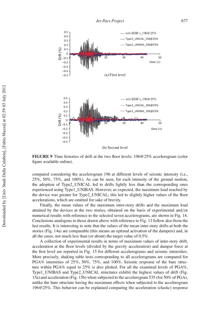
At rst, time histories of drift at the two oor levels of the test structures are shown in
Fig. 9 for the experimental test No. 5, which corresponds to the accelerogram 196 and to a
level of seismic intensity (i.e., PGA%=25%), preventing the occurrence of yielding of the
bare structure. As can be observed, the bare structure shows values of the drift at the second level (in Fig. 9b, max,II ∼
=0.5%) higher than those recorded at the rst level (in Fig. 9a,
max,I ∼
=0.35%). On the other hand, Type1_UNIBAS and Type2_UNICAL structures provide comparable results, ensuring a remarkable reduction of the response also for such a
level of seismic intensity which corresponds to the achievement of the limit state of damage
for the bare structure. More speci cally, a reduction of the maximum drift above the 100%,
in comparison with that of the bare structure, and a comparable response at both the oor
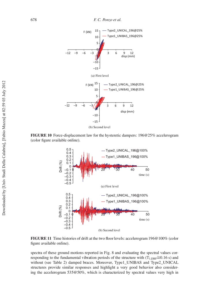
levels can be pointed out. Finally, the force-displacement laws for the hysteretic dampers
of Type1_UNIBAS and Type2_UNICAL structures (only a damper for each level is
considered according to the symmetry in plan) highlight a comparable behavior (Fig. 10).
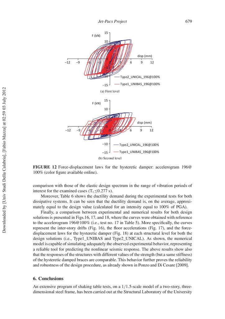
Curves analogous to those just shown are reported in Figs. 11 and 12, referring to
the accelerogram 196 for the level of seismic intensity equal to 100%. The comparison is
restricted to the damped braced structures, because the test on the bare structure has been
not executed expecting damage of the frame members. Time histories of drift at the two
oor levels exhibit a similar trend, with a maximum value of about 0.4%, which is comparable with the maximum values previously observed for the bare structure subjected to the
accelerogram 196@25%. Moreover, Type1_UNIBAS and Type2_UNICAL structures have
analogous responses in terms of drift (Fig. 11) and a stable hysteretic behaviour with a large
damping capacity as regards the force-displacement laws of the hysteretic dampers (Fig.
12), con rming reliability and effectiveness of the retro tting technique even changing the
design solution.
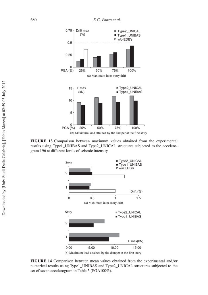
Afterwards, the maximum inter-story drift (Fig. 13a) and the maximum load attained
by the damper at the rst story (Fig. 13b), both measured for the two design solutions, are
17.
Drift (%)Downloaded by [Univ Studi Della Calabria], [Fabio Mazza] at 02:59 03 July 2012
Drift (%)
Jet-Pacs Project
0.5
0.4
0.3
0.2
0.1
0
–0.1 0
–0.2
–0.3
–0.4
–0.5
0.5
0.4
0.3
0.2
0.1
0
–0.1 0
–0.2
–0.3
–0.4
–0.5
677
w/o EDB’s_196@25%
Type2_UNICAL_196@25%
Type1_UNIBAS_196@25%
10
20
30
40
50
time (s)
(a) First level
w/o EDB’s_196@25%
Type2_UNICAL_196@25%
Type1_UNIBAS_196@25%
10
20
30
40
50
time (s)
(b) Second level
FIGURE 9 Time histories of drift at the two oor levels: 196@25% accelerogram (color
gure available online).
compared considering the accelerogram 196 at different levels of seismic intensity (i.e.,
25%, 50%, 75%, and 100%). As can be seen, for each intensity of the ground motion,
the adoption of Type2_UNICAL led to drifts lightly less than the corresponding ones
experienced using Type1_UNIBAS. However, as expected, the maximum load reached by
the device was greater for Type2_UNICAL; this led to slightly higher values of the oor
accelerations, which are omitted for sake of brevity.
Finally, the mean values of the maximum inter-story drifts and the maximum load
attained by the devices at the two stories, obtained on the basis of experimental and/or
numerical results with reference to the selected seven accelerograms, are shown in Fig. 14.
Conclusions analogous to those drawn above with reference to Fig. 13 follow also from the
last results. It is interesting to note that the values of the mean inter-story drifts at both the
stories (Fig. 14a) are comparable (this means an optimal activation of the dampers) and, in
all the cases, not much less than (or about) the target value of 0.5%.
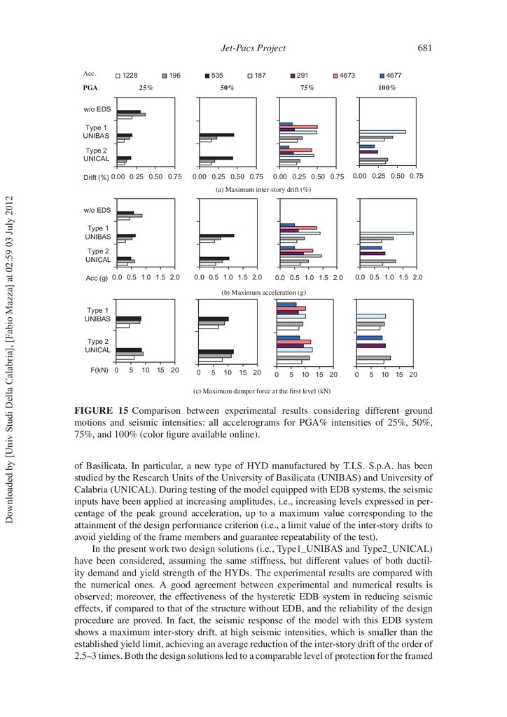
A collection of experimental results in terms of maximum values of inter-story drift,
acceleration at the oor levels (divided by the gravity acceleration) and damper force at
the rst level are reported in Fig. 15 for different accelerograms and seismic intensities.
More precisely, shaking table tests corresponding to all accelerograms are compared for
PGA% intensities of 25%, 50%, 75%, and 100%. Seismic response of the bare structure within PGA% equal to 25% is also plotted. For all the examined levels of PGA%,
Type1_UNIBAS and Type2_UNICAL structures exhibit the highest values of drift (Fig.
15a) and acceleration (Fig. 15b) when subjected to the accelerogram 535 (for 50% of PGA),
unlike the bare structure having the maximum effects when subjected to the accelerogram
196@25%. This behavior can be explained comparing the acceleration (elastic) response
18.
678F. C. Ponzo et al.
F (kN)
15
Type2_UNICAL_196@25%
10
Type1_UNIBAS_196@25%
5
0
Ð12
Ð9
Ð6
Ð3
Ð5
0
3
6
9
12
disp (mm)
Ð10
Ð15
F (kN)
15
Type2_UNICAL_196@25%
10
Type1_UNIBAS_196@25%
5
Ð12
Ð9
Ð6
Ð3
0
Ð5
0
3
6
9
12
disp (mm)
Ð10
Ð15
(b) Second level
Drift (%)
FIGURE 10 Force-displacement law for the hysteretic dampers: 196@25% accelerogram
(color gure available online).
0.5
0.4
0.3
0.2
0.1
0
–0.1 0
–0.2
–0.3
–0.4
–0.5
Type2_UNICAL_196@100%
Type1_UNIBAS_196@100%
10
20
30
40
50
time (s)
(a) First level
Drift (%)
Downloaded by [Univ Studi Della Calabria], [Fabio Mazza] at 02:59 03 July 2012
(a) First level
0.5
0.4
0.3
0.2
0.1
0
–0.1 0
–0.2
–0.3
–0.4
–0.5
Type2_UNICAL_196@100%
Type1_UNIBAS_196@100%
10
20
30
40
50
time (s)
(b) Second level
FIGURE 11 Time histories of drift at the two oor levels: accelerogram 196@100% (color
gure available online).
spectra of these ground motions reported in Fig. 8 and evaluating the spectral values corresponding to the fundamental vibration periods of the structure with (T1,DBF ∼
=0.16 s) and
without (see Table 2) damped braces. Moreover, Type1_UNIBAS and Type2_UNICAL
structures provide similar responses and highlight a very good behavior also considering the accelerogram 535@50%, which is characterized by spectral values very high in
19.
Jet-Pacs Project679
15
F (kN)
10
5
Ð12
Ð9
Ð6
Ð3
0
disp (mm)
0
3
6
9
12
Downloaded by [Univ Studi Della Calabria], [Fabio Mazza] at 02:59 03 July 2012
Ð5
Ð10
Type2_UNICAL_196@100%
Ð15
Type1_UNIBAS_196@100%
(a) First level
F (kN)
15
10
5
disp (mm)
0
Ð12
Ð9
Ð6
Ð3
0
3
6
9
12
Ð5
Ð10
Type2_UNICAL_196@100%
Ð15
Type1_UNIBAS_196@100%
(b) Second level
FIGURE 12 Force-displacement laws for the hysteretic damper: accelerogram 196@
100% (color gure available online).
comparison with those of the elastic design spectrum in the range of vibration periods of
interest for the examined cases (T1 ≤0.277 s).
Moreover, Table 6 shows the ductility demand during the experimental tests for both
dissipative systems. It can be seen that the ductility demand is, on the average, approximately equal to the design value (calculated for an intensity equal to 100% of PGA).
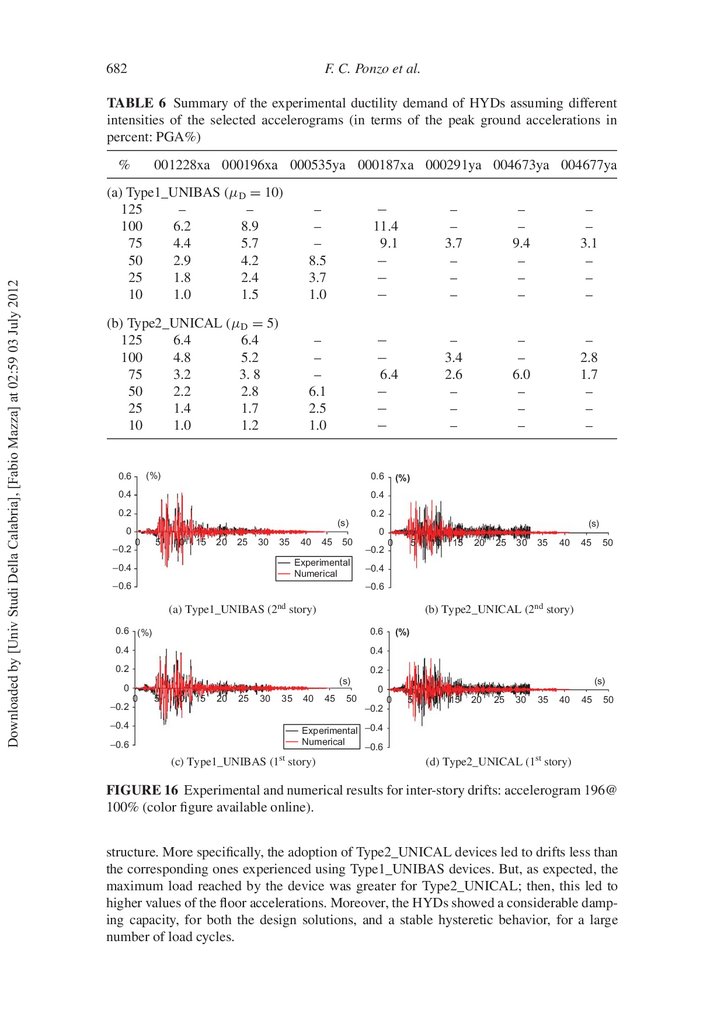
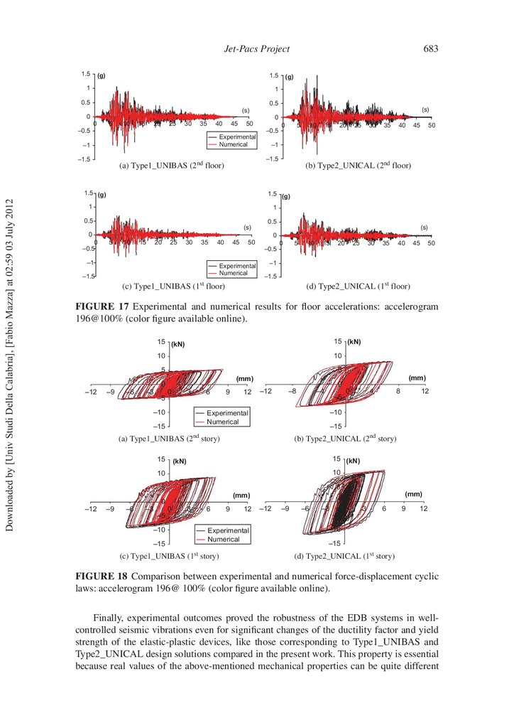
Finally, a comparison between experimental and numerical results for both design
solutions is presented in Figs.16, 17, and 18, where the curves were obtained with reference
to the accelerogram 196@100% (i.e., test no. 17 in Table 5). More speci cally, the curves
represent the inter-story drifts (Fig. 16), the oor accelerations (Fig. 17), and the forcedisplacement laws for the hysteretic damper (Fig. 18) at each structural level for both the
design solutions (i.e., Type1_UNIBAS and Type2_UNICAL). As shown, the numerical
model is capable of simulating adequately the observed experimental behavior, representing
a reliable tool for predicting the nonlinear seismic response. The above results show also
that the responses of the structures with different values of the strength (but a same stiffness)
of the hysteretic damped braces are comparable. This behavior further proves the reliability
and robustness of the design procedure, as already shown in Ponzo and Di Cesare [2009].
6. Conclusions
An extensive program of shaking table tests, on a 1/1.5-scale model of a two-story, threedimensional steel frame, has been carried out at the Structural Laboratory of the University
20.
680F. C. Ponzo et al.
0.75
Drift max
(%)
Type2_UNICAL
Type1_UNIBAS
w/o EDB's
0.5
0.25
0
PGA (%)
25%
50%
75%
100%
Downloaded by [Univ Studi Della Calabria], [Fabio Mazza] at 02:59 03 July 2012
(a) Maximum inter-story drift
15
Type2_UNICAL
Type1_UNIBAS
F max
(kN)
10
5
0
PGA (%) 25%
50%
75%
100%
(b) Maximum load attained by the damper at the first story
FIGURE 13 Comparison between maximum values obtained from the experimental
results using Type1_UNIBAS and Type2_UNICAL structures subjected to the accelerogram 196 at different levels of seismic intensity.
Type2_UNICAL
Type1_UNIBAS
w/o EDB's
Story
2
1
Drift (%)
0
0.5
1
(a) Maximum inter-story drift
Story
1.5
Type2_UNICAL
Type1_UNIBAS
2
1
F max(kN)
0.00
5.00
10.00
15.00
(b) Maximum load attained by the damper at the first story
FIGURE 14 Comparison between mean values obtained from the experimental and/or
numerical results using Type1_UNIBAS and Type2_UNICAL structures subjected to the
set of seven accelerogram in Table 5 (PGA100%).
21.
Jet-Pacs ProjectAcc.
1228
PGA
196
535
25%
681
187
291
4673
4677
50%
75%
100%
0.00 0.25 0.50 0.75
0.00 0.25 0.50 0.75
0.00 0.25 0.50 0.75
w/o EDS
Type 1
UNIBAS
Type 2
UNICAL
Drift (%) 0.00 0.25 0.50 0.75
Downloaded by [Univ Studi Della Calabria], [Fabio Mazza] at 02:59 03 July 2012
(a) Maximum inter-story drift (%)
w/o EDS
Type 1
UNIBAS
Type 2
UNICAL
Acc (g) 0.0 0.5 1.0 1.5 2.0
0.0 0.5 1.0 1.5 2.0
0.0 0.5 1.0 1.5 2.0
0.0 0.5 1.0 1.5 2.0
(b) Maximum acceleration (g)
Type 1
UNIBAS
Type 2
UNICAL
F(kN) 0
5
10
15 20
0
5
10
15 20
0
5
10 15 20
0
5
10 15 20
(c) Maximum damper force at the first level (kN)
FIGURE 15 Comparison between experimental results considering different ground
motions and seismic intensities: all accelerograms for PGA% intensities of 25%, 50%,
75%, and 100% (color gure available online).
of Basilicata. In particular, a new type of HYD manufactured by T.I.S. S.p.A. has been
studied by the Research Units of the University of Basilicata (UNIBAS) and University of
Calabria (UNICAL). During testing of the model equipped with EDB systems, the seismic
inputs have been applied at increasing amplitudes, i.e., increasing levels expressed in percentage of the peak ground acceleration, up to a maximum value corresponding to the
attainment of the design performance criterion (i.e., a limit value of the inter-story drifts to
avoid yielding of the frame members and guarantee repeatability of the test).
In the present work two design solutions (i.e., Type1_UNIBAS and Type2_UNICAL)
have been considered, assuming the same stiffness, but different values of both ductility demand and yield strength of the HYDs. The experimental results are compared with
the numerical ones. A good agreement between experimental and numerical results is
observed; moreover, the effectiveness of the hysteretic EDB system in reducing seismic
effects, if compared to that of the structure without EDB, and the reliability of the design
procedure are proved. In fact, the seismic response of the model with this EDB system
shows a maximum inter-story drift, at high seismic intensities, which is smaller than the
established yield limit, achieving an average reduction of the inter-story drift of the order of
2.5–3 times. Both the design solutions led to a comparable level of protection for the framed
22.
682F. C. Ponzo et al.
TABLE 6 Summary of the experimental ductility demand of HYDs assuming different
intensities of the selected accelerograms (in terms of the peak ground accelerations in
percent: PGA%)
Downloaded by [Univ Studi Della Calabria], [Fabio Mazza] at 02:59 03 July 2012
%
001228xa 000196xa 000535ya 000187xa 000291ya 004673ya 004677ya
(a) Type1_UNIBAS (μD = 10)
125
–
–
100
6.2
8.9
75
4.4
5.7
50
2.9
4.2
25
1.8
2.4
10
1.0
1.5
–
–
–
8.5
3.7
1.0
−
11.4
9.1
−
−
−
–
–
3.7
–
–
–
–
–
9.4
–
–
–
–
–
3.1
–
–
–
(b) Type2_UNICAL (μD = 5)
125
6.4
6.4
100
4.8
5.2
75
3.2
3. 8
50
2.2
2.8
25
1.4
1.7
10
1.0
1.2
–
–
–
6.1
2.5
1.0
−
−
6.4
−
−
−
–
3.4
2.6
–
–
–
–
–
6.0
–
–
–
–
2.8
1.7
–
–
–
(%)
0.6
0.6
0.4
0.4
0.2
0.2
(s)
0
–0.2
(%)
(s)
0
0
5
10
15
20
25
30
35
40
45
50
Experimental
Numerical
–0.4
–0.6
–0.2
0
5
25
30
35
40
45
50
(b) Type2_UNICAL (2nd story)
0.6
0.4
0.4
0.2
(%)
0.2
(s)
0
–0.6
20
–0.6
0.6 (%)
–0.4
15
–0.4
(a) Type1_UNIBAS (2nd story)
–0.2
10
0
5
10
15
20
25
30
35
40
45
(s)
0
50
0
5
10
15
20
25
30
35
40
45
50
–0.2
Experimental –0.4
Numerical
–0.6
(c) Type1_UNIBAS (1st story)
(d) Type2_UNICAL (1st story)
FIGURE 16 Experimental and numerical results for inter-story drifts: accelerogram 196@
100% (color gure available online).
structure. More speci cally, the adoption of Type2_UNICAL devices led to drifts less than
the corresponding ones experienced using Type1_UNIBAS devices. But, as expected, the
maximum load reached by the device was greater for Type2_UNICAL; then, this led to
higher values of the oor accelerations. Moreover, the HYDs showed a considerable damping capacity, for both the design solutions, and a stable hysteretic behavior, for a large
number of load cycles.
23.
Jet-Pacs Project1.5
1.5
(g)
1
683
(g)
1
0.5
0.5
(s)
(s)
0
0
0
5
10
15
20
25
30
35
40
45
50
–0.5
–0.5
Experimental
Numerical
–1
–1.5
Downloaded by [Univ Studi Della Calabria], [Fabio Mazza] at 02:59 03 July 2012
5
10
15
20
25
30
35
40
45
50
–1
–1.5
(a) Type1_UNIBAS (2nd floor)
1.5 (g)
(b) Type2_UNICAL (2nd floor)
1.5 (g)
1
1
0.5
(s)
0.5
0
0
–0.5
0
(s)
0
5
10
15
20
25
30
35
40
45
50
–0.5
–1
Experimental
Numerical
–1.5
0
5
10
15
20
25
30
35
40
45
50
–1
–1.5
(d) Type2_UNICAL (1st floor)
(c) Type1_UNIBAS (1st floor)
FIGURE 17 Experimental and numerical results for oor accelerations: accelerogram
196@100% (color gure available online).
15 (kN)
15 (kN)
10
10
5
5
(mm)
0
–12
–9
–6
–3
–5
3
0
6
–10
9
12
–12
–8
–4
–5
10
5
5
–3
(mm)
(mm)
0
–6
12
15 (kN)
(kN)
10
–9
8
(b) Type2_UNICAL (2nd story)
(a) Type1_UNIBAS (2 story)
–12
4
–15
nd
15
0
–10
Experimental
Numerical
–15
(mm)
0
0
3
6
9
12
–5
–10
Experimental
Numerical
–15
(c) Type1_UNIBAS
(1st
story)
0
–12
–9
–6
–3
–5
0
3
6
9
12
–10
–15
(d) Type2_UNICAL (1st story)
FIGURE 18 Comparison between experimental and numerical force-displacement cyclic
laws: accelerogram 196@ 100% (color gure available online).
Finally, experimental outcomes proved the robustness of the EDB systems in wellcontrolled seismic vibrations even for signi cant changes of the ductility factor and yield
strength of the elastic-plastic devices, like those corresponding to Type1_UNIBAS and
Type2_UNICAL design solutions compared in the present work. This property is essential
because real values of the above-mentioned mechanical properties can be quite different
24.
684F. C. Ponzo et al.
from the design values due to industrial standardization in the production of the devices
and/or some their damage suffered during previous earthquakes.
Acknowledgments
Downloaded by [Univ Studi Della Calabria], [Fabio Mazza] at 02:59 03 July 2012
The present work was nanced by R.E.L.U.I.S. (Italian network of university laboratories
of earthquake engineering), within the “D.P.C. – R.E.L.U.I.S. Project 11/07/2005 (item
540) research line no. 7”.
References
Antonacci, E., De Stefano, A., Gattulli, V., Lepidi, M., and Matta, E. [2011] “Comparative study
of vibration-based parametric identi cation techniques for a three-dimensional frame structure,”
Structural Control and Health Monitoring, Wiley Online Library, John Wiley & Sons, Ltd, pp.
1–30.
Bertero, V. V. [2002] “ Innovative approaches to earthquake engineering,” ed. G. Oliveto, (University
of Catania [Italy],WIT Press [Ashurst, Southampton, UK]), pp. 1–84.
Bouc, R. [1967] “ Forced vibration of mechanical systems with hysteresis,” Proc. of the 4th
International Conference on Nonlinear Oscillation, Prague, Czechoslovakia.
Christopoulos, C. and Filiatrault, A. [2006] “Principles of passive supplemental damping and seismic
isolation,” IUSS Press, Istituto Universitario di Studi Superiori di Pavia, Pavia, Italy.
Ciampi, V. [1989] “Un sistema di controventi dissipative per strutture antisismiche in acciaio,”
International Meeting on Base Isolation and Passive Energy Dissipation, Assisi, Italy, pp,
17.01–17.16.
Ciampi, V. [1993] “Development of passive energy dissipation techniques for buildings,”
International Post-SMIRT Conference Seminar on Seismic Isolation, Energy Dissipation and
Control of Vibrations of Structures, Capri, Italy, pp. 495–510.
CSI [2004] SAP2000: Static and Dynamic Finite Element Analysis of Structures, Computers and
Structures, Inc„ Berkeley, CA.
De Stefano, A., Matta, E., and Quattrone, A. [2008] “Dynamic identi cation and model-updating of
the JETPACS prototype,” DPC-RELUIS Research Project No. 7, JETPACS Report No. 4, Torino,
Italy.
Di Cesare, A., Ponzo, F. C., Auletta, G., and Gilio A. [2011] “Behaviour factor of concrete structures
with hysteretic energy dissipating bracing system,” Proc. of the XIV ANIDIS L’Ingegneria Sismica
in Italia, Bari, Italy, Paper No. 294.
Dolce, M., Filardi, B., Marnetto, R., and Nigro, D. [1996], “Experimental tests and applications of
a new biaxial elasto-plastic device for the passive control of structures,” Proc. of the 4th World
Congress on Joint Sealants and Bearing Systems for Concrete Structures, Sacramento, CA.
Dolce, M., Ponzo, F.C., Di Cesare, A., Ditommaso, R., Moroni, C., Nigro, D., Serino, G., Sorace,
S., Gattulli, V., Occhiuzzi, A., Vulcano, A., and Foti, D. [2008] “JET-PACS project: Joint
Experimental Testing on Passive and Semiactive Control Systems, Proc. of the 14th World
Conference on Earthquake Engineering, Beijing, China, Paper No. 183, pp. 651–674.
Eurocode 8 [2003] Design of Structures for Earthquake Resistance - Part 1: General Rules, Seismic
Actions and Rules for Buildings, C.E.N., European Committee for Standardization, Brussels,
Belgium, pp. 1–210.
European Commission for Community Research. European Strong Motion Database (on-line), http://
www.isesd.cv.ic. ac.uk/ESD.
FEMA-ASCE 356 [2000] Prestandard and Commentary for the Seismic Rehabilitation of
Buildings. Federal Emergency Management Agency and American Society of Civil Engineering,
Washington, D.C.
Gattulli, V., Lepidi, M., and Potenza, F. [2007] “Identi cation of analytical and nite element models
for the JETPACS three-dimensional frame,” DPC-RELUIS Research Project No. 7, JETPACS
Report No. 2, L’Aquila, Italy.
25.
Downloaded by [Univ Studi Della Calabria], [Fabio Mazza] at 02:59 03 July 2012Jet-Pacs Project
685
Iervolino, I., Maddaloni, G., and Cosenza, E. [2008] “Eurocode 8 compliant real record sets for
seismic analysis of structures,” Journal of Structural Engineering 12, 54–90.
Kelly, J. M., Skinner, R. I., and Heine, A. J. [1972] “Mechanisms of energy absorption in special device for use in earthquake resistant structures,” Bulletin of the New Zealand Society of
Earthquake Engineering 5(3), 63–88.
Kim, J. and Choi, H. [2006] “Displacement-based design of supplemental dampers for seismic retro t
of a framed structure,” Journal of Structural Engineering 132(6), 873–883.
Kim, J., Choi, H., and Min, K. W. [2003] “Performance-based design of added viscous dampers using
capacity spectrum method,” Journal of Earthquake Engineering 7(1), 1–24.
Martìnez-Rueda, J. E. [2002] “On the evolution of energy dissipation devices for seismic design,”
Earthquake Spectra 18(2), 309–346.
Mazza, F. and Vulcano, A. [2008] “Displacement-based seismic design procedure for framed
buildings with dissipative braces. (a) Part I: Theoretical formulation; (b) Part II: Numerical
results,” 2008 Seismic Engineering International Conference Commemorating the 1908 Messina
and Reggio Calabria Earthquake (MERCEA08), Reggio Calabria (Italy), American Institute of
Physics Conference Proceedings (Melville, NY, USA), Vol. 1020 (part two).
NTC [2008] “Italian Technical Code for Constructions (in Italian),” DM 14 gennaio 2008, Rome,
Italy.
Ponzo, F. C., Cardone, D., Di Cesare, A., Moroni, C., Nigro, D., and Vigoriti, G. [2007a] “Dynamic
tests on JETPACS steel frame: experimental model set up,” DPC-RELUIS Research Project No. 7,
JETPACS Report No. 3, pp. 1–20.
Ponzo, F. C., Dolce, M., Di Cesare A, Vigoriti, G., and Arleo, G. [2007b] “A design procedure
for energy dissipating displacement-dependent bracing system for r/c buildings,” Proc. of the
10th World Conference on Seismic Isolation, Energy Dissipation and Active Vibrations Control of
Structures, Istanbul (Turkey), Paper No. 77.
Ponzo, F. C. and Di Cesare, A. [2009] “Numerical and experimental assessment of the robustness
of a seismic upgrading technique for framed buildings based on hysteretic dissipating devices,”
Proc. of the 11th World Conference on Seismic Isolation, Energy Dissipation and Active Vibration
Control of Structures, Guangzhou (China), Paper No. 61.
Serino, G., Chandrasekaran, S., Marsico, M. R., and Spizzuoco, M. [2008] “Descriptions and analytical modelling of the Jetpacs prototype steel frame,” DPC-RELUIS Research Project No. 7,
JETPACS Report No. 1, pp. 1–31.
Soong, T. T. and Dargush, G. F. [1997] Passive Energy Dissipation Systems in Structural Engineering,
John Wiley & Sons Ltd, Chichester, UK.
Tsai, K. C., Chen, H. W., Hong, C. P., and Su, Y. F. [1993] “Design of steel triangular plate energy
absorbers for seismic-resistant construction,” Earthquake Spectra 9(3), 505–528.
Vulcano, A. and Mazza, F. [2002] “A simpli ed procedure for the aseismic design of framed buildings with dissipative braces,” Proc. of the 12th European Conference on Earthquake Engineering,
London, Paper No 735.
Wen, Y. K. [1976] “Method of random vibration of hysteretic systems,” Journal of Engineering
Mechanics 102, 249–263.
Whittaker, A. S., Bertero, V. V., Thompson, C. L,. and Alonso, L. J. [1991] “Seismic testing of steel
plate energy dissipation devices,” Earthquake Spectra 7(4), 563–604.