 Строительство
Похожие презентации:


International Journal of Civil Engineering and Technology (IJCIET)
1.
International Journal of Civil Engineering and Technology (IJCIET)Volume 8, Issue 2, February 2017, pp. 289–299 Article ID: IJCIET_08_02_031
Available online at http://www.iaeme.com/IJCIET/issues.asp?JType=IJCIET&VType=8&IType=2
ISSN Print: 0976-6308 and ISSN Online: 0976-6316
© IAEME Publication
Scopus Indexed
SEISMIC PROTECTION OF RC FRAMES USING
FRICTION DAMPERS
A.K. Sinha
Professor and Centre Director, Earthquake Safety Clinic and Centre, Department of Civil Engineering,
National Institute of Technology Patna, Patna, Bihar, India
Sharad Singh
Research Scholar, Structural Engineering, Department of Civil Engineering, National Institute of
Technology Patna, Patna, Bihar, India
ABSTRACT
The increasing infrastructural growth incurs large investments and large section of society
being served by them, it is necessary to make them safer against earthquakes and let people
feel confident in their structures. The need for structural response control has gained pace in
application around the globe. This paper discusses the use and effectiveness of one such
device, friction dampers, for response control of structures. In this paper a non-linear time
history analysis has been carried out on a 3D model of a 12 story RCC MRF building using 3directional synthetic accelerogram. Two different cases of building models with and without
friction dampers have been analyzed using ETABS. The response of the structure to seismic
excitation in terms of absolute maximum displacement and story drift has been compared.
Time history response plots have also been compared for various responses viz. roof
displacement and acceleration, base shear and story shear forces, along with the various
energy components and damping behavior. The results of the time history analysis are in close
conformation with previous investigations and represent the effectiveness of dampers in
improving the structural response as well as damping demand on structural systems.
Key words: Structural response control, Non-linear time history analysis, Friction dampers,
supplemental damping.
Cite this Article: A.K. Sinha and Sharad Singh, Seismic Protection of RC Frames Using
Friction Dampers. International Journal of Civil Engineering and Technology, 8(2), 2017, pp.
289–299.
http://www.iaeme.com/IJCIET/issues.asp?JType=IJCIET&VType=8&IType=2
1. INTRODUCTION
The dynamic behavior of structure reveals the manner in which the structure responds to external
excitation. The concept of structural response control has been active for more than a century and in
last few decades notable advancement has been done in the field to make it a practical solution. The
reduction of structural response caused by dynamic effects has become a subject of intensive research.
Several concepts have evolved in this advancement but with only a few implementations in practice.
Numerous motivation have conducted towards this research like reduction of undesirable vibrational
http://www.iaeme.com/IJCIET/index.asp
289
[email protected]
2.
Seismic Protection of RC Frames Using Friction Damperslevels, retrofitting existing structures, protecting equipment and important secondary systems and
eventually to provide new concepts of design of structures. The concept of response control dates long
back into history but the first known formal concept was introduced by James T.P. Yao in 1972 [11].
Until than several experimentations by individual investigators had already been carried out as early as
1890s.The structural control using energy dissipation which is based on modification of energy
absorption can be achieved in many ways [15]. For any structural system under dynamic loading the
entrant energy is dissipated naturally by various damping mechanisms acting simultaneously [3, 15].
A comprehensive review of PED concepts and application available in published literature [21] shows
that addition of PED devices to structural system reduces the excessive deformation and ductility
demands and at the same time enhances its energy dissipation capacity. The application to structural
systems to resist wind and earthquake induced vibration has only been known for a couple of decades
only after pioneering investigations of Housner in 1956 [11], on energy balance approach for design
procedure. The dynamic behavior of the structure installed with Friction Damper (FD) can be
represented by equation (1).
M ̈ + C ̇ + {Ku+ ∆ ℎ( )} =−M ̈ g
(1)
Where M is the mass matrix, C is the damping coefficient matrix, K is stiffness matrix, k0 is the
stiffness of damper brace system, ∆ is the displacement of the damper brace system, h(t) is hysteretic
variable for the friction damper, ̈ is acceleration, ̇ is velocity, u is displacement, and ̈ g is ground
acceleration.
The mass and stiffness contribution of damper brace system to the dynamic behavior of structures,
even though very small as compared to those of structural members, should be incorporated in
analysis. Investigations have been carried out to use FD in RC buildings for dynamic response control.
Various devices utilizing friction for energy dissipation have been developed and tested. Various
forms of friction have been used to reduce vibrations and the most popular type being solid friction
[21]. Friction devices do not change the inherent properties of the structure, their cost is relatively low,
and their installation and maintenance are simple [14]. Pall et.al developed friction joints (Pall
Friction dampers) for concrete walls and framed structures [16]. A series of static and dynamic tests
have been performed on passive friction dampers using various combinations of sliding materials and
surface treatments to identify one that provides a consistent and predictable response [16]. Various
modifications have been suggested in the friction damped bracing systems are the tension-only and
tension-compression bracing systems [18]. Investigations on proposals of Pall and Marsh [16] have
reaffirmed the practicality of FDs [6, 7, 10]. A superior performance of friction damped braced frames
(FDBFs) has been shown compared to traditional earthquake resisting systems [2, 6]. Furthermore
energy dissipation is concentrated in the dampers rather than due to the inelastic behavior of the
structural members. Translational FD depends on ground motion and hence for small excitation they
do not slip and dissipate energy. Research and applications around the globe demonstrate that friction
dampers represent an inexpensive and effective way to reduce seismic response parameters without
hampering the integrity of the structural elements [19]. Pall friction dampers also add stiffness to the
structure and a large amount of energy is dissipated through friction rather than any other mode where
a damping of 20 to 50% of critical is achieved. No external energy source is needed to operate and no
maintenance or replacement of device after earthquakes is needed [20]. Recent research on friction
dampers focuses mainly on their utilization as a (semi) active control system.
2. MATHEMATICAL MODEL FOR FRICTION DAMPER
The idealized force displacement curve for a damper is shown (Figure 1). The equivalent stiffness
and damping
for a damper can be evaluated using the curve as [21, 22]:
=
∆
(2)
∆
http://www.iaeme.com/IJCIET/index.asp
290
[email protected]
3.
A.K. Sinha and Sharad Singh=
(3)
∆
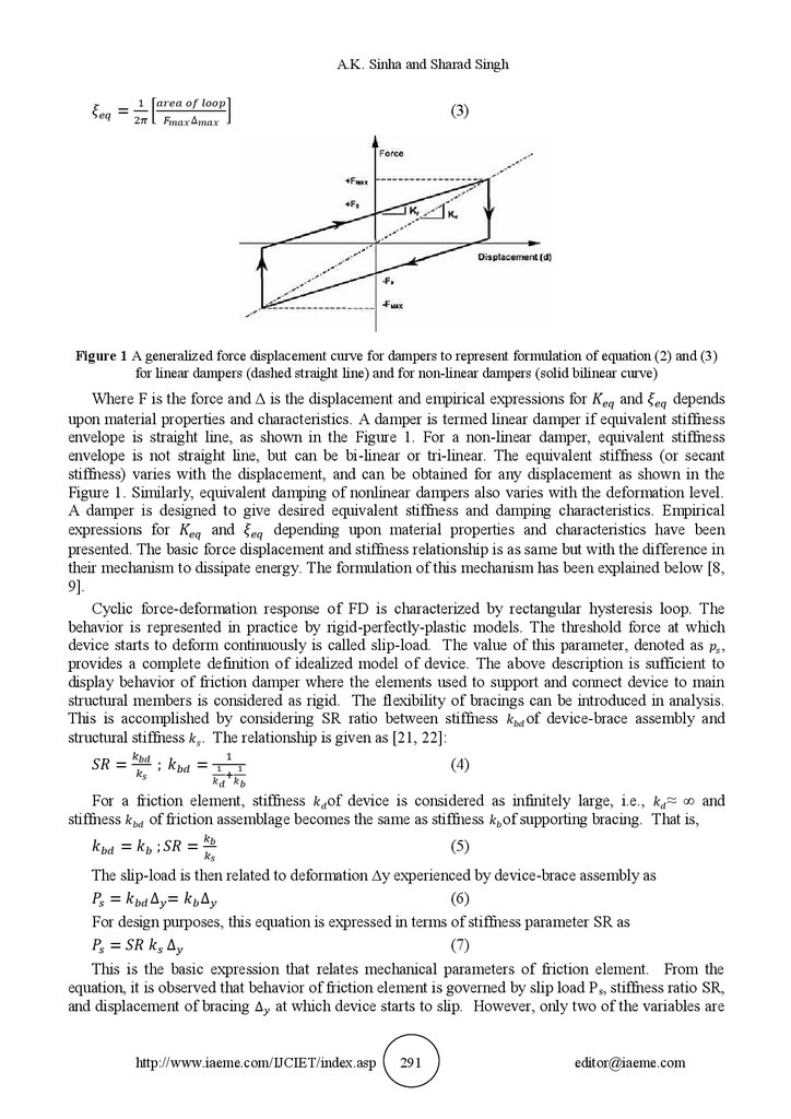
Figure 1 A generalized force displacement curve for dampers to represent formulation of equation (2) and (3)
for linear dampers (dashed straight line) and for non-linear dampers (solid bilinear curve)
Where F is the force and Δ is the displacement and empirical expressions for
and
depends
upon material properties and characteristics. A damper is termed linear damper if equivalent stiffness
envelope is straight line, as shown in the Figure 1. For a non-linear damper, equivalent stiffness
envelope is not straight line, but can be bi-linear or tri-linear. The equivalent stiffness (or secant
stiffness) varies with the displacement, and can be obtained for any displacement as shown in the
Figure 1. Similarly, equivalent damping of nonlinear dampers also varies with the deformation level.
A damper is designed to give desired equivalent stiffness and damping characteristics. Empirical
expressions for
and
depending upon material properties and characteristics have been
presented. The basic force displacement and stiffness relationship is as same but with the difference in
their mechanism to dissipate energy. The formulation of this mechanism has been explained below [8,
9].
Cyclic force-deformation response of FD is characterized by rectangular hysteresis loop. The
behavior is represented in practice by rigid-perfectly-plastic models. The threshold force at which
device starts to deform continuously is called slip-load. The value of this parameter, denoted as ,
provides a complete definition of idealized model of device. The above description is sufficient to
display behavior of friction damper where the elements used to support and connect device to main
structural members is considered as rigid. The flexibility of bracings can be introduced in analysis.
This is accomplished by considering SR ratio between stiffness
of device-brace assembly and
structural stiffness . The relationship is given as [21, 22]:
=
;
(4)
=
For a friction element, stiffness of device is considered as infinitely large, i.e., ≈ ∞ and
stiffness
of friction assemblage becomes the same as stiffness of supporting bracing. That is,
=
;
(5)
=
The slip-load is then related to deformation ∆y experienced by device-brace assembly as
=
∆ = ∆
(6)
For design purposes, this equation is expressed in terms of stiffness parameter SR as
=
∆
(7)
This is the basic expression that relates mechanical parameters of friction element. From the
equation, it is observed that behavior of friction element is governed by slip load P s, stiffness ratio SR,
and displacement of bracing ∆ at which device starts to slip. However, only two of the variables are
http://www.iaeme.com/IJCIET/index.asp
291
[email protected]
4.
Seismic Protection of RC Frames Using Friction Dampersindependent since the third one can be determined from above expression. The hysteretic behavior of
friction element is also characterized using continuous Bouc-Wen’s model. Recognizing the absence
of any post-yielding or strain hardening effect, force P(t) developed in friction element is obtained as
( ) = ∆ ℎ( )
(8)
∆ ℎ( ̇ ) − ∆( ̇ ) + ∆( ̇ ) ℎ( )|ℎ( )|
+ ∆( ̇ )|ℎ( )| = 0
(9)
The model parameters H, Y, β and n can be adjusted to approximate the shape of hysteresis loop.
A value of n = 2, with H = 1 and Y+β = 1 (β = 0.1, Y = 0.9) have been proposed in the literature to
produce loops of frictional forces versus sliding displacements that are in good agreement with
experimental results. If flexibility of bracing is included in analysis, hysteretic loop of friction
assemblage is better approximated by use of a suitable value of exponent coefficient n. The remaining
model parameters, and ,is related to the mechanical properties of friction element. This is done by
considering that at slipping condition, hysteretic variable h(t) takes values of ±1, and friction element
force P(t) is equal to slip-load . Thus, it is easily shown that
=
(10)
;∆ =
3. PARAMETERIC CONSIDERATIONS
3.1. Structural Modeling
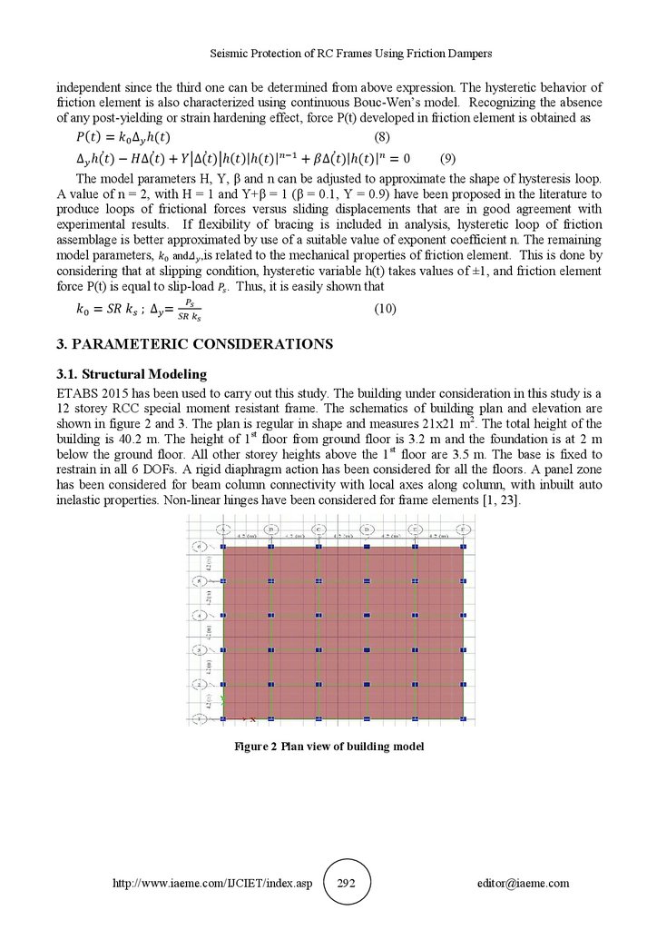
ETABS 2015 has been used to carry out this study. The building under consideration in this study is a
12 storey RCC special moment resistant frame. The schematics of building plan and elevation are
shown in figure 2 and 3. The plan is regular in shape and measures 21x21 m2. The total height of the
building is 40.2 m. The height of 1 st floor from ground floor is 3.2 m and the foundation is at 2 m
below the ground floor. All other storey heights above the 1st floor are 3.5 m. The base is fixed to
restrain in all 6 DOFs. A rigid diaphragm action has been considered for all the floors. A panel zone
has been considered for beam column connectivity with local axes along column, with inbuilt auto
inelastic properties. Non-linear hinges have been considered for frame elements [1, 23].
Figure 2 Plan view of building model
http://www.iaeme.com/IJCIET/index.asp
292
[email protected]
5.
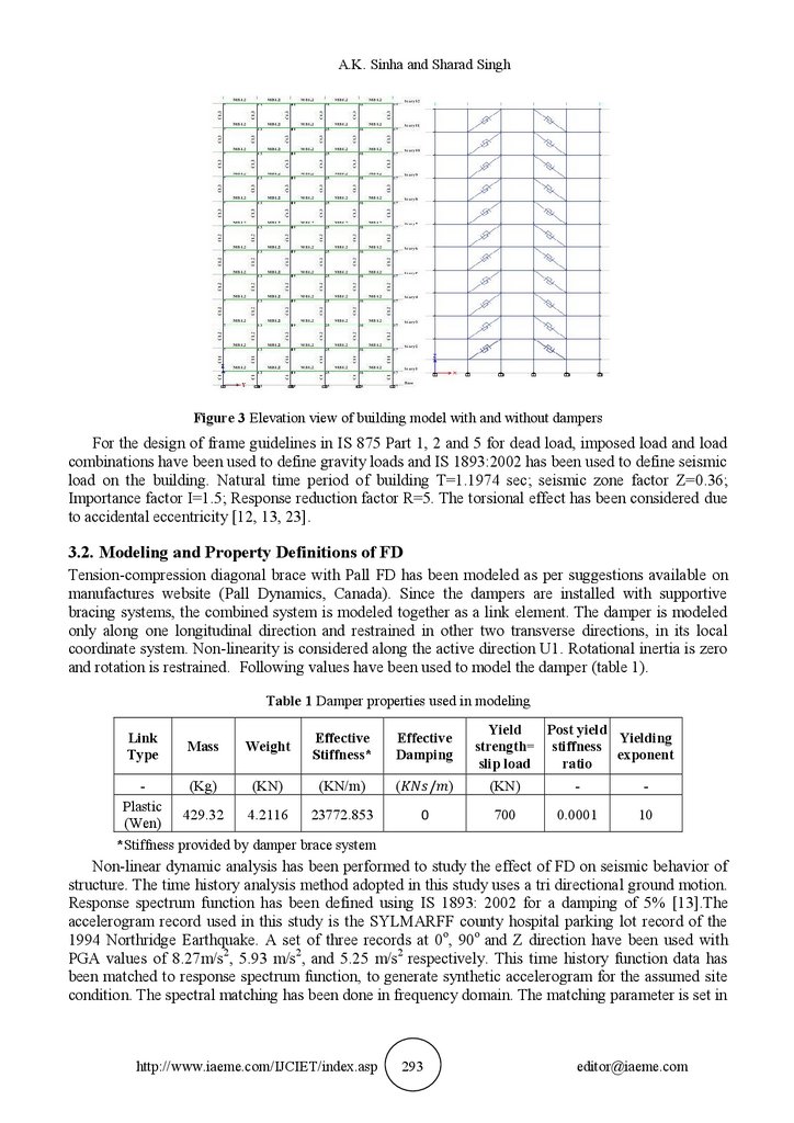
A.K. Sinha and Sharad SinghFigure 3 Elevation view of building model with and without dampers
For the design of frame guidelines in IS 875 Part 1, 2 and 5 for dead load, imposed load and load
combinations have been used to define gravity loads and IS 1893:2002 has been used to define seismic
load on the building. Natural time period of building T=1.1974 sec; seismic zone factor Z=0.36;
Importance factor I=1.5; Response reduction factor R=5. The torsional effect has been considered due
to accidental eccentricity [12, 13, 23].
3.2. Modeling and Property Definitions of FD
Tension-compression diagonal brace with Pall FD has been modeled as per suggestions available on
manufactures website (Pall Dynamics, Canada). Since the dampers are installed with supportive
bracing systems, the combined system is modeled together as a link element. The damper is modeled
only along one longitudinal direction and restrained in other two transverse directions, in its local
coordinate system. Non-linearity is considered along the active direction U1. Rotational inertia is zero
and rotation is restrained. Following values have been used to model the damper (table 1).
Table 1 Damper properties used in modeling
Link
Type
Mass
Weight
Effective
Stiffness*
(Kg)
(KN)
(KN/m)
Plastic
429.32
4.2116
23772.853
(Wen)
*Stiffness provided by damper brace system
Effective
Damping
(
/ )
0
Yield
Post yield
Yielding
strength= stiffness
exponent
ratio
slip load
(KN)
-
-
700
0.0001
10
Non-linear dynamic analysis has been performed to study the effect of FD on seismic behavior of
structure. The time history analysis method adopted in this study uses a tri directional ground motion.
Response spectrum function has been defined using IS 1893: 2002 for a damping of 5% [13].The
accelerogram record used in this study is the SYLMARFF county hospital parking lot record of the
1994 Northridge Earthquake. A set of three records at 0o, 90o and Z direction have been used with
PGA values of 8.27m/s2, 5.93 m/s2, and 5.25 m/s2 respectively. This time history function data has
been matched to response spectrum function, to generate synthetic accelerogram for the assumed site
condition. The spectral matching has been done in frequency domain. The matching parameter is set in
http://www.iaeme.com/IJCIET/index.asp
293
[email protected]
6.
Seismic Protection of RC Frames Using Friction Dampersa frequency range of 0.01 cycles/sec to 100 cycles/sec. The 3 synthetic accelerogram in 3 directions
(U1, U2 and U3) are applied simultaneously, to create realistic ground motion condition [22, 23].
4. RESULTS AND DISCUSSION
For the modal analysis carried out for 12 modes following time periods have been noted down (tables
2) in each case for frame with and without supplemental damping. From the table for time period it
can be easily seen that the time period of the oscillation of the structure has shifted to lower values on
addition of dampers to the system to as much as 35% reduction in time period. The variation along the
modes is considerable [3, 4, 5].
Table 2 Time period for buildings with and without supplemental damping for various modes
Mode No.
1
2
3
4
5
6
7
8
9
10
11
12
Without FD
1.246
1.246
0.422
0.422
0.235
0.235
0.171
0.159
0.14
0.107
0.07
0.053
Time Period is in sec.
with FD
1.075
1.075
0.363
0.363
0.199
0.199
0.135
0.135
0.091
0.091
0.045
0.045
4.1. Results of Non-Linear Time History Analysis
The results of non-linear time history analysis (THA) have been studied for both storey responses in
terms of storey v/s storey response as well as time history functions of the responses. The storey
responses considered here are absolute maximum storey displacement (AMSD) and absolute
maximum storey drift (AMSd).
4.1.1. Absolute Max. Storey Displacements (mm)
AMSD has been plotted for THA in both X and Y directions for all the stories. The plot shows the
effectiveness of damper in controlling the story displacement response of the structure. In either case
the maximum displacement is at the roof level and minimum at the base level storey. For building
model with FD the maximum storey displacement attained at top story is 139.732 mm in global Xdirection and 90.667 mm in global Y-direction as compared to 174.218 mm and 149.635 mm for
building model without damper at top story in global X and Y directions respectively. A lower AMSD
value for building with damper shows the effectiveness of dampers in controlling the response of the
structure [4, 5, 17].
4.1.2. Absolute Max. Storey Drift (Unit less)
The Absolute maximum storey drift in terms of inter-story drift ratio (IDR) of different stories has
been obtained for both global X and Y directions. The code suggests a limiting value of 0.004 times
the storey height for drift in any storey i.e. 0.014 m [3]. The IDR values has been obtained using the
following formula
IDR= (Dn+1 – Dn)/Hn
(9)
http://www.iaeme.com/IJCIET/index.asp
294
[email protected]
7.
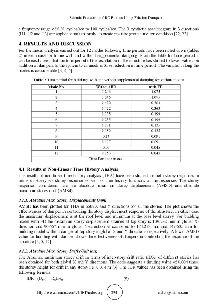
A.K. Sinha and Sharad SinghWhere, Dn+1 is the displacement of upper floor or n+1th floor, Dn is the displacement of lower floor
or nth floor and Hn is the storey height or floor separation for the given storey.
Figure 4 AMSD for building with and without supplemental damping in Global X and Y directions
Figure 5 IDR v/s storey plot for building with and without supplemental damping in Global X and Y Directions
The IDR plot shows that this value is exceeded in both the cases. The maximum value of IDR for
building without damper is 0.0068 and 0.0055 in global X and Y directions respectively at story 4.
Whereas the maximum value for building with damper is 0.0051 at story 4 in global X-direction and
0.0033 at story 5 in global Y-direction. The value of IDR has been controlled within the limiting value
of 0.004 in the case of building with FD except for stories 3,4 and 5 where it has exceeded the limiting
value in global X-direction. Even though the drift exceeds the limiting value for building with dampers
at storey 4 it is comparatively lower than the drift for building without damper.
4.2. Time History of Responses
The response of the structure for THA has been plotted as time history functions of response against
time in global X-direction. The TH plots give better insight into the response behavior of structure at
each time step of analysis. The time history plot has been represented for following responses viz.
Roof displacement, Roof Acceleration, Base Shear force, and storey shear force.
http://www.iaeme.com/IJCIET/index.asp
295
[email protected]
8.
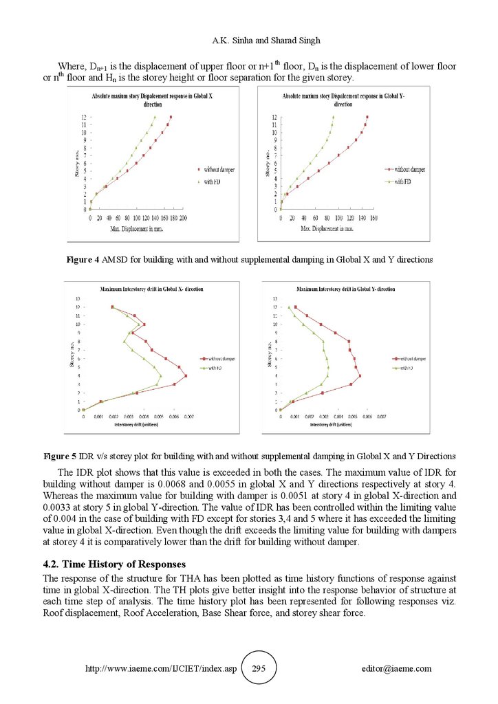
Seismic Protection of RC Frames Using Friction DampersFigure 6 Roof displacement and acceleration v/s time plots in global X-direction for building with and without
supplemental damping
4.2.1. Roof Displacement and Roof Acceleration
Roof displacement and acceleration are important parameters to analyze the response of structure
under dynamic loading and gives a better insight into performance of the structure as a whole. Plots of
roof displacement v/s time period and roof acceleration v/s time period for two building models with
and without supplemental damping under seismic loading have been generated. The displacement
plots reveal that displacement values for building without dampers is as high as 174.218 mm which is
subsequently lower for building model with FD with maximum displacement as high as 139.732 mm.
The use of dampers has successfully reduced the displacement values at all-time instances in
comparison to building without dampers and has managed to keep the overall displacement of building
within a limited range with smooth transitions preventing sudden reversal of displacement load.
Similar interpretation can be made for roof acceleration time history response. The roof acceleration
for building with damper is as high as 8.72 m/sec2 which is even higher than the maximum roof
acceleration of 5.99 m/sce2 for building without dampers.
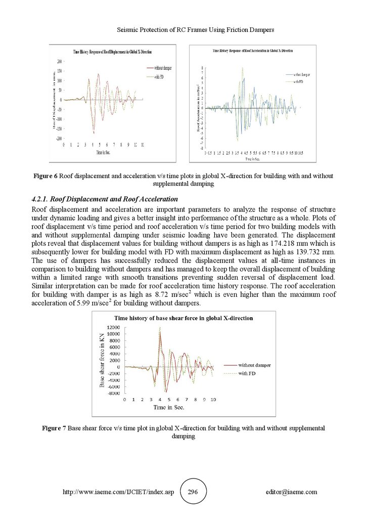
Figure 7 Base shear force v/s time plot in global X-direction for building with and without supplemental
damping
http://www.iaeme.com/IJCIET/index.asp
296
[email protected]
9.
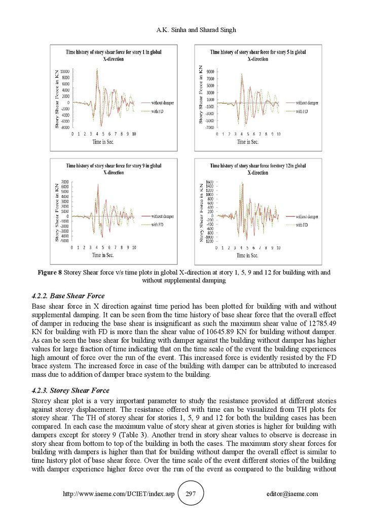
A.K. Sinha and Sharad SinghFigure 8 Storey Shear force v/s time plots in global X-direction at story 1, 5, 9 and 12 for building with and
without supplemental damping
4.2.2. Base Shear Force
Base shear force in X direction against time period has been plotted for building with and without
supplemental damping. It can be seen from the time history of base shear force that the overall effect
of damper in reducing the base shear is insignificant as such the maximum shear value of 12785.49
KN for building with FD is more than the shear value of 10645.89 KN for building without damper.
As can be seen the base shear for building with damper against the building without damper has higher
values for large fraction of time indicating that on the time scale of the event the building experiences
high amount of force over the run of the event. This increased force is evidently resisted by the FD
brace system. The increased force in case of the building with damper can be attributed to increased
mass due to addition of damper brace system to the building.
4.2.3. Storey Shear Force
Storey shear plot is a very important parameter to study the resistance provided at different stories
against storey displacement. The resistance offered with time can be visualized from TH plots for
storey shear. The TH of storey shear for stories 1, 5, 9 and 12 for both the building cases has been
compared. In each case the maximum value of story shear at given stories is higher for building with
dampers except for storey 9 (Table 3). Another trend in story shear values to observe is decrease in
story shear from bottom to top of the building in both the cases. The maximum story shear forces for
building with dampers is higher than that for building without damper the overall effect is similar to
time history plot of base shear force. Over the time scale of the event different stories of the building
with damper experience higher force over the run of the event as compared to the building without
http://www.iaeme.com/IJCIET/index.asp
297
[email protected]
10.
Seismic Protection of RC Frames Using Friction Dampersdamper. Again as stated for base shear force the higher value of story shear in case of building with
damper can be attributed to the increased mass by addition of damper brace systemat each story level.
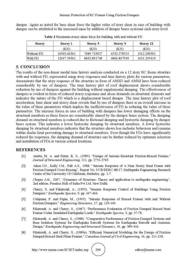
Table 3 Maximum storey shear force for building with and without FD
Storey
Without FD
With FD
Storey 1
Storey 5
Storey 9
Storey 12
(KN)
10503.66361
12647.54961
(KN)
7689.719927
8602.891748
(KN)
6532.578515
4866.847959
(KN)
1512.290501
1631.295419
5. CONCLUSION
The results of the non-linear modal time history analysis conducted on a 12 story RC frame structure
with and without FD, represented using story responses and time history plots for various parameters,
demonstrate that the story response of the structure in form of AMSD and AMSd have been reduced
considerably by use of dampers. The time history plot of roof displacement shows considerable
reduction by use of dampers against the building without supplemental damping. The effectiveness of
dampers is evident in form of reduced storey responses and stress demands on structural elements and
indicates the nature of the FD which is a displacement based damper. The time history plot of roof
acceleration, base shear and storey shear reveals that by use of dampers there is an overall increase in
the value of these parameters which implies the ineffectiveness of FD in reducing the value of these
parameters. The increase forces in case of building with dampers has lower damaging effects on the
structural members as these forces are considerably shared by the damper brace system. The damping
demand on structural members is reduced due to frictional damping and hysteretic damping by damper
brace system. This indicates a lower hysteretic damping by structural members. A lower hysteretic
damping by structural members indicates that the structure shows less inelastic behaviour and remains
within elastic limit preventing damage to structural members. Even though the FDs have significantly
reduced the responses, the damping demand of structure can be further reduced by optimum selection
and installation of FDs at various critical locations.
REFERENCES
[1]
Austin, M. A. and Pister, K. S., (1985). "Design of Seismic-Resistant Friction-Braced Frames,"
Journal of Structural Engineering, 111, pp. 2751-2769.
[2]
Aiken I.D., Kelly J.M., Pall A.S., 1988, “Seismic Response of A Nine Storey Steel Frame with
Friction Damped Cross Bracing”, Report No. UCB/EERC-88/17, Earthquake Engineering Research
Centre of the University Of California, Berkeley, pp. 1-7.
[3]
Chopra A.K., 2007, “Dynamics of Structure- Theory and application to earthquake engineering”,
2nd edition. Prentice Hall of India Pvt Ltd, New Delhi.
[4]
Cherry, S. and Filiatrault, A., (1993). "Seismic Response Control of Buildings Using Friction
Dampers," Earthquake Spectra, 9, pp. 447-466.
[5]
Colajanni, P. and Papia, M., (1995). "Seismic Response of Braced Frames with and Without
Friction Dampers," Engineering Structures, 17, pp. 129-140.
[6]
Filiatrault, A. and Cherry, S., (1987). "Performance Evaluation of Friction Damped Braced Steel
Frames Under Simulated Earthquake Loads," Earthquake Spectra, 3, pp. 57-78.
[7]
Filiatrault, A. and Cherry, S., (1988). "Comparative Performance of Friction Damped Systems and
Base Isolation Systems for Earthquake Retrofit Systems for Earthquake Retrofit and Aseismic
Design," Earthquake Engineering and Structural Dynamics, 16, pp. 389-416.
[8]
Filiatrault, A. and Cherry, S., (1989a). "Efficient Numerical Modeling for the Design of Friction
Damped Braced Steel Plane Frames," Canadian Journal of Civil Engineering, 16, pp. 211-218.
http://www.iaeme.com/IJCIET/index.asp
298
[email protected]
11.
A.K. Sinha and Sharad Singh[9]
Filiatrault, A. and Cherry, S., (1989b). "Parameters Influencing the Design of Friction Damped
Structures," Canadian Journal of Civil Engineering, 16, pp. 753-766.
[10]
Filiatrault, A. and Cherry, S., (1990). "Seismic Design Spectra for Friction-Damped Structures,"
Journal of Structural Engineering, 116, pp. 1334-1355.
[11]
Housner, G. W., Bergman, L. A., Caughey, T. K., Chassiakos, A. G., Claus, R. O., Masri, S. F.,
Skelton, R. E., Soong, T. T., Spencer, B. F., and Yao, J. T. P., (1997). "Structural Control: Past,
Present, and Future," Journal of Engineering Mechanics, 123(9), pp. 897-971.
[12]
IS: 456 -2000, Code of Practice for Plain and Reinforced Concrete.
[13]
IS: 1893(Part-I)-2002, Criteria for Earthquake Resistant Design of Structures, Fifth Revision.
[14]
Mualla I.H., Belev B., 2002, “performance of steel frames with a new friction damper device under
earthquake excitation”, Engineering Structures, 24, pp. 365-371.
[15]
PankajAggarwal& Manish Shrikhande, “Earthquake resistant design of structures”, ISBN-81-2032892-2, Prentice Hall of India Pvt Ltd, M-97, Connaught Circus, New Delhi (India) 110001.
[16]
Pall, A. S., Marsh, C., and Fazio, P., (1980). "Friction Joints for Seismic Control of Large Panel
Structures," Journal of the Prestressed Concrete Institute, 25(6), pp. 38-61.
[17]
Pall, A. S. and Marsh, C., (1982). "Response of Friction Damped Braced Frames," Journal of
Structural Engineering, 108(ST6), pp. 1313-1323.
[18]
Pall A.S., 1983, “friction devices for aseismic design of buildings”, proceedings of IV Canadian
conference on earthquake engineering, pp. 475-484.
[19]
Pall, A. S. and Pall, R., (1993). "Friction-Dampers Used for Seismic Control of New and Existing
Buildings in Canada," ATC-17-1 Seminar on Seismic Isolation, Passive Energy Dissipation, and
Active Control, San Francisco, CA, pp. 675-686.
[20]
Pall A.S., Pall T., 2004, “performance based design using pall friction dampers-an economical
design solution”, proceedings of 13th world conference on earthquake engineering, Vancouver,
B.C., Canada, Paper no 1955.
[21]
Soong T.T., Dargush G.F., “Passive Energy Dissipation Systems In Structural Engineering”, ISBN
978-0-471-96821-4, John Wiley &Sons (Asia) Pte Ltd, 2 Clementi Loop, # 02-01, Singapore
129809, 1997.
[22]
T. K. Datta, Indian Institute Of Technology Delhi, India, “Seismic Analysis Of Structures”, ISBN
978-0-470-82461-0 (HB), John Wiley & Sons (Asia) Pte Ltd, 2 Clementi Loop, # 02-01, Singapore
129809, 2010.
[23]
A.K. Sinha and Sharad Singh, Structural Response Control of RCC Moment Resisting Frame Using
Fluid Viscous Dampers. International Journal of Civil Engineering and Technology, 8(1), 2017, pp.
900–910
[24]
M.E. Ephraim and T.C. Nwofor, Experimental Modeling of in Filled RC Frames with Opening,
International Journal of Civil Engineering and Technology, 7(2), 2016, pp. 95–106.
[25]
A.K. Sinha and Sharad Singh, Structural Response Control of RCC Moment Resisting Frame Using
Fluid Viscous Dampers. International Journal of Civil Engineering and Technology, 8(1), 2017,
pp. 900–910
http://www.iaeme.com/IJCIET/index.asp
299
[email protected]