 Электроника
 Реклама
Похожие презентации:
")
")

![PBA Repair Guide [GT-S8000]](https://cf.ppt-online.org/files/thumb/t/tIHBnfpml5G6E47aLocdVU0kDZQNvuejRhAMC8.jpg "PBA Repair Guide [GT-S8000]")
")


HW Repair Guide SM-G7102 ( Galaxy Grand 2)
1.
HW Repair Guide SM-G7102( Galaxy Grand 2)
Service Excellence Beyond Imagination
SWA-CS Content Innovation
2.
NOTICE1. All functionality, features, specifications and other product information
provided in this document including, but not limited to, the benefits, design,
pricing, components, performance, availability, and capabilities of the product are
subject to change without notice or obligation. Samsung reserves the right to
make changes to this document and the product described herein, at anytime, with
out obligation on Samsung to provide notification of such change.
2. In data of our company, important management / technical information is
included, and if it is leaked, loss can happen in various aspect such as closing a
technology gap, increasing ability to respond. Therefore, it is strictly prohibited from
information leak or forwarding this material, and if leak of management / technical
information due to disobeying the law happens, it can be severely punished in
accordance with information protection rule of our company.
Service Excellence Beyond Imagination
SWA-CS Content Innovation
3.
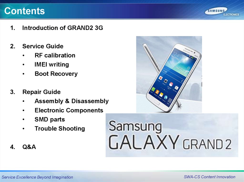
Contents1.
Introduction of GRAND2 3G
2.
Service Guide
RF calibration
IMEI writing
Boot Recovery
3.
Repair Guide
Assembly & Disassembly
Electronic Components
SMD parts
4.
Trouble Shooting
Q&A
Service Excellence Beyond Imagination
SWA-CS Content Innovation
4.
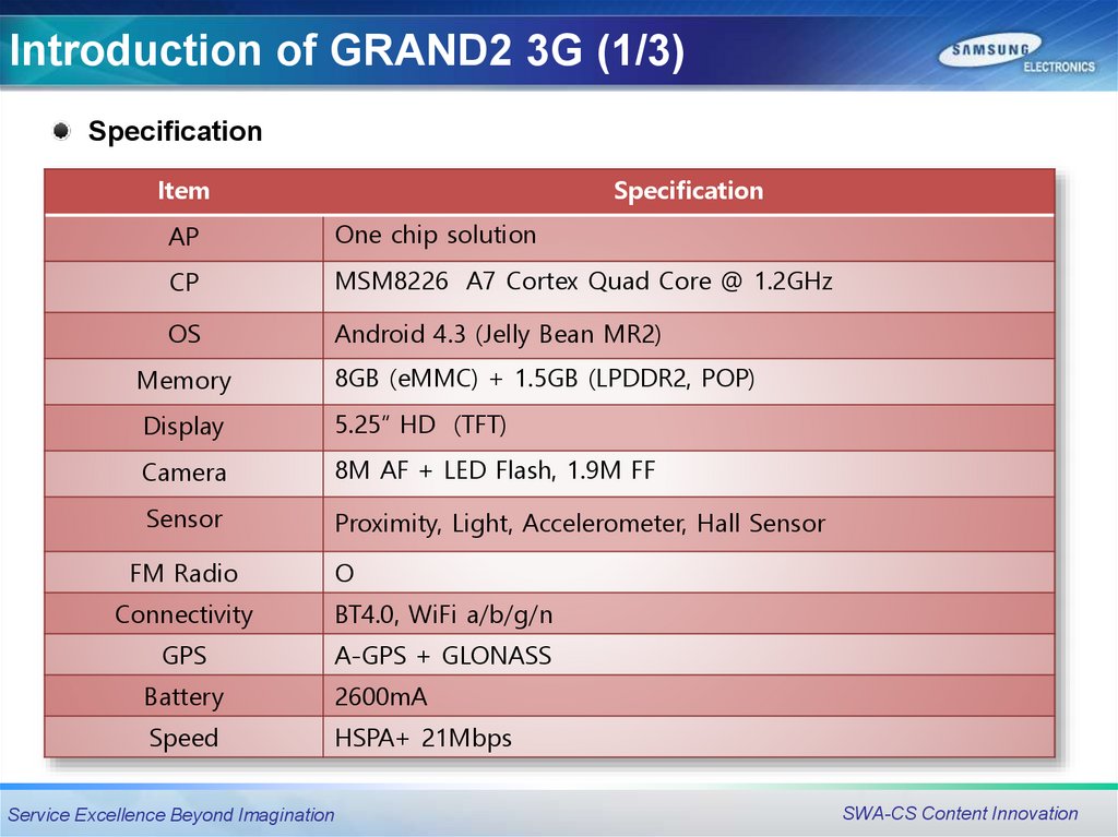
Introduction of GRAND2 3G (1/3)Specification
Item
Specification
AP
One chip solution
CP
MSM8226 A7 Cortex Quad Core @ 1.2GHz
OS
Android 4.3 (Jelly Bean MR2)
Memory
8GB (eMMC) + 1.5GB (LPDDR2, POP)
Display
5.25” HD (TFT)
Camera
8M AF + LED Flash, 1.9M FF
Sensor
Proximity, Light, Accelerometer, Hall Sensor
FM Radio
O
Connectivity
BT4.0, WiFi a/b/g/n
GPS
A-GPS + GLONASS
Battery
2600mA
Speed
HSPA+ 21Mbps
Service Excellence Beyond Imagination
SWA-CS Content Innovation
5.
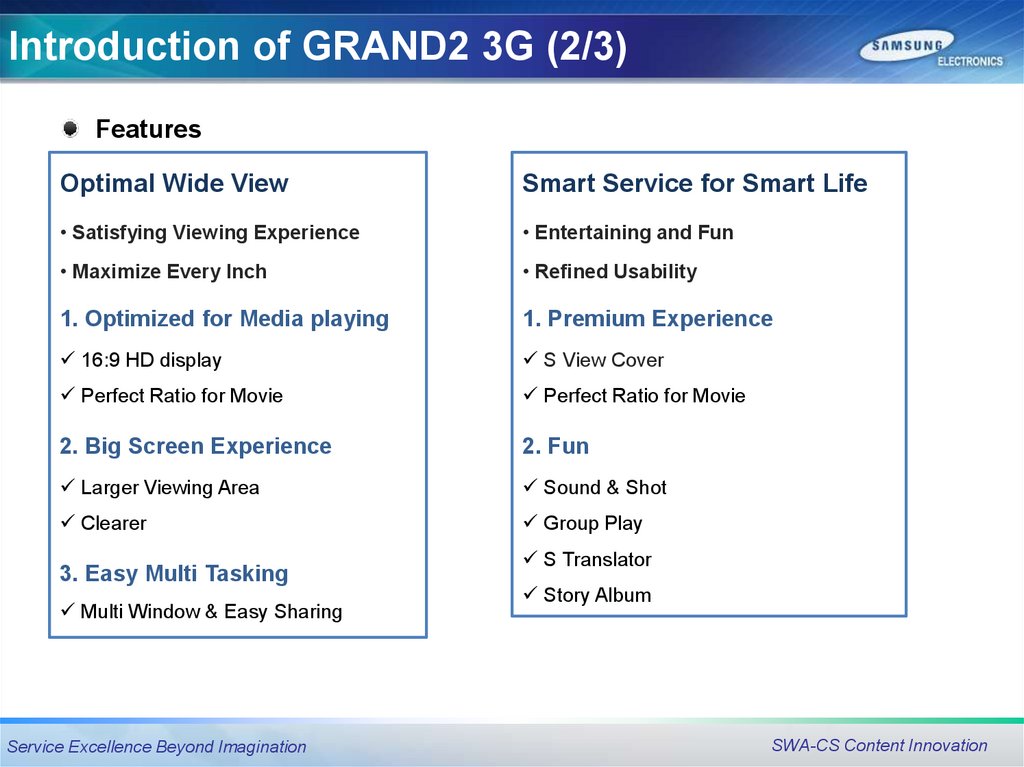
Introduction of GRAND2 3G (2/3)Features
Optimal Wide View
Smart Service for Smart Life
• Satisfying Viewing Experience
• Entertaining and Fun
• Maximize Every Inch
• Refined Usability
1. Optimized for Media playing
1. Premium Experience
16:9 HD display
S View Cover
Perfect Ratio for Movie
Perfect Ratio for Movie
2. Big Screen Experience
2. Fun
Larger Viewing Area
Sound & Shot
Clearer
Group Play
3. Easy Multi Tasking
Multi Window & Easy Sharing
Service Excellence Beyond Imagination
S Translator
Story Album
SWA-CS Content Innovation
6.
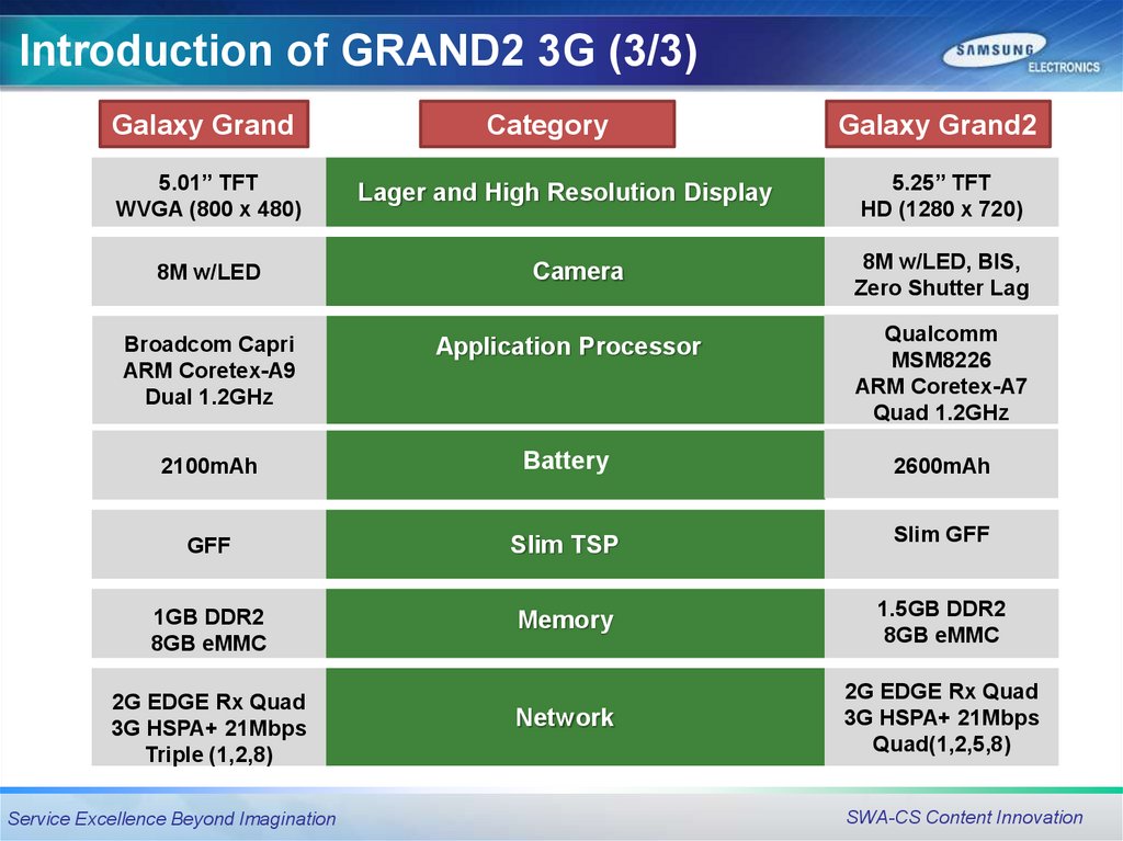
Introduction of GRAND2 3G (3/3)Galaxy Grand
5.01” TFT
WVGA (800 x 480)
8M w/LED
Category
Lager and High Resolution Display
Camera
Galaxy Grand2
5.25” TFT
HD (1280 x 720)
8M w/LED, BIS,
Zero Shutter Lag
Broadcom Capri
ARM Coretex-A9
Dual 1.2GHz
Application Processor
Qualcomm
MSM8226
ARM Coretex-A7
Quad 1.2GHz
2100mAh
Battery
2600mAh
GFF
Slim TSP
Slim GFF
1GB DDR2
8GB eMMC
Memory
1.5GB DDR2
8GB eMMC
Network
2G EDGE Rx Quad
3G HSPA+ 21Mbps
Quad(1,2,5,8)
2G EDGE Rx Quad
3G HSPA+ 21Mbps
Triple (1,2,8)
Service Excellence Beyond Imagination
SWA-CS Content Innovation
7.
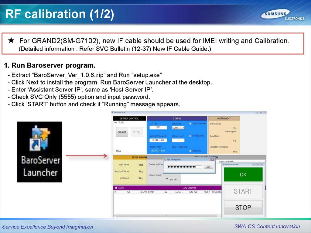
RF calibration (1/2)★
For GRAND2(SM-G7102), new IF cable should be used for IMEI writing and Calibration.
(Detailed information : Refer SVC Bulletin (12-37) New IF Cable Guide.)
1. Run Baroserver program.
- Extract “BaroServer_Ver_1.0.6.zip” and Run “setup.exe”
- Click Next to install the program. Run BaroServer Launcher at the desktop.
- Enter ‘Assistant Server IP’, same as ‘Host Server IP’.
- Check SVC Only (5555) option and input password.
- Click ‘START’ button and check if “Running” message appears.
Service Excellence Beyond Imagination
SWA-CS Content Innovation
8.
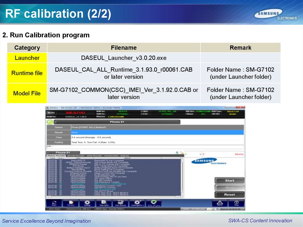
RF calibration (2/2)2. Run Calibration program
Category
Filename
Launcher
DASEUL_Launcher_v3.0.20.exe
Runtime file
DASEUL_CAL_ALL_Runtime_3.1.93.0_r00061.CAB
or later version
Folder Name : SM-G7102
(under Launcher folder)
Model File
SM-G7102_COMMON(CSC)_IMEI_Ver_3.1.92.0.CAB or
later version
Folder Name : SM-G7102
(under Launcher folder)
Service Excellence Beyond Imagination
Remark
SWA-CS Content Innovation
9.
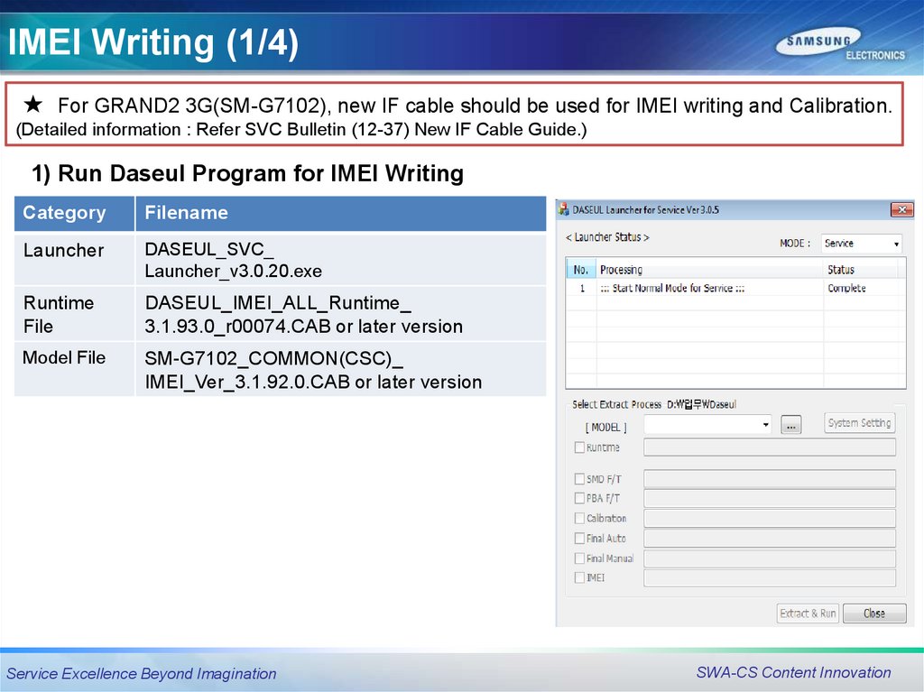
IMEI Writing (1/4)★
For GRAND2 3G(SM-G7102), new IF cable should be used for IMEI writing and Calibration.
(Detailed information : Refer SVC Bulletin (12-37) New IF Cable Guide.)
1) Run Daseul Program for IMEI Writing
Category
Filename
Launcher
DASEUL_SVC_
Launcher_v3.0.20.exe
Runtime
File
DASEUL_IMEI_ALL_Runtime_
3.1.93.0_r00074.CAB or later version
Model File
SM-G7102_COMMON(CSC)_
IMEI_Ver_3.1.92.0.CAB or later version
Service Excellence Beyond Imagination
SWA-CS Content Innovation
10.
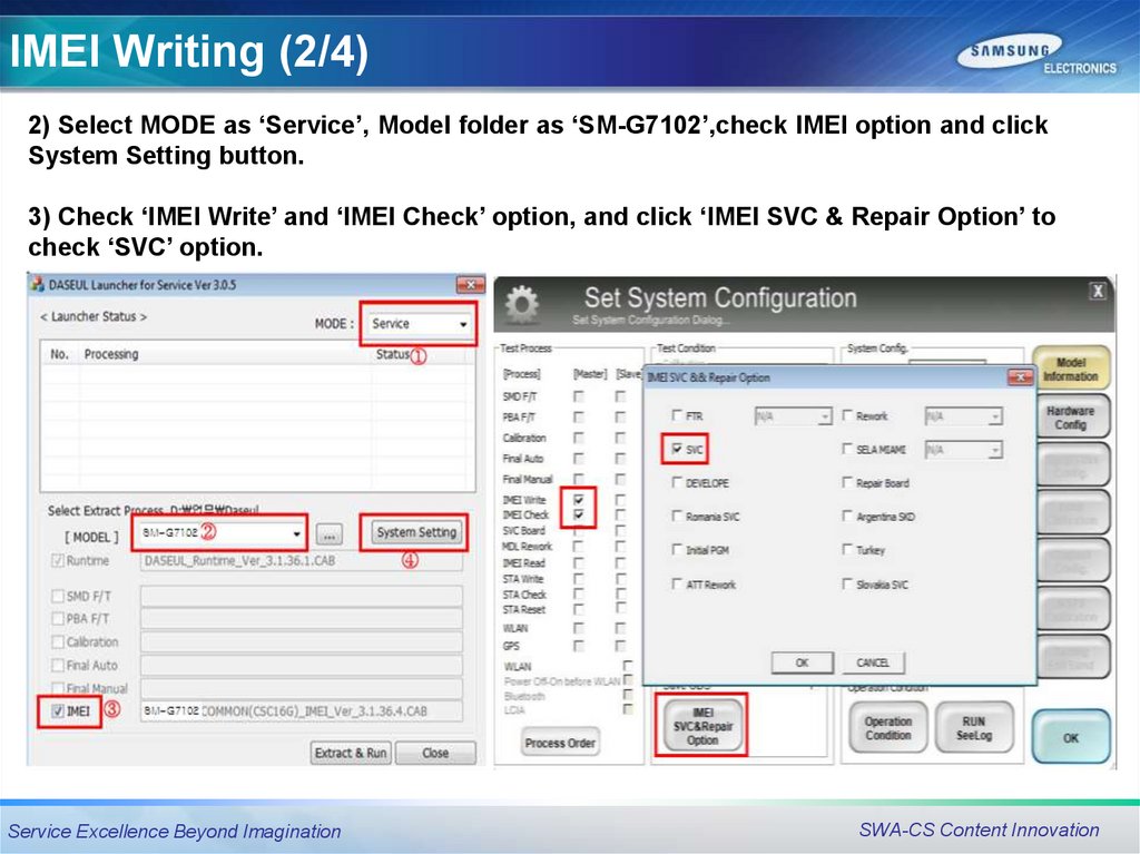
IMEI Writing (2/4)2) Select MODE as ‘Service’, Model folder as ‘SM-G7102’,check IMEI option and click
System Setting button.
3) Check ‘IMEI Write’ and ‘IMEI Check’ option, and click ‘IMEI SVC & Repair Option’ to
check ‘SVC’ option.
Service Excellence Beyond Imagination
SWA-CS Content Innovation
11.
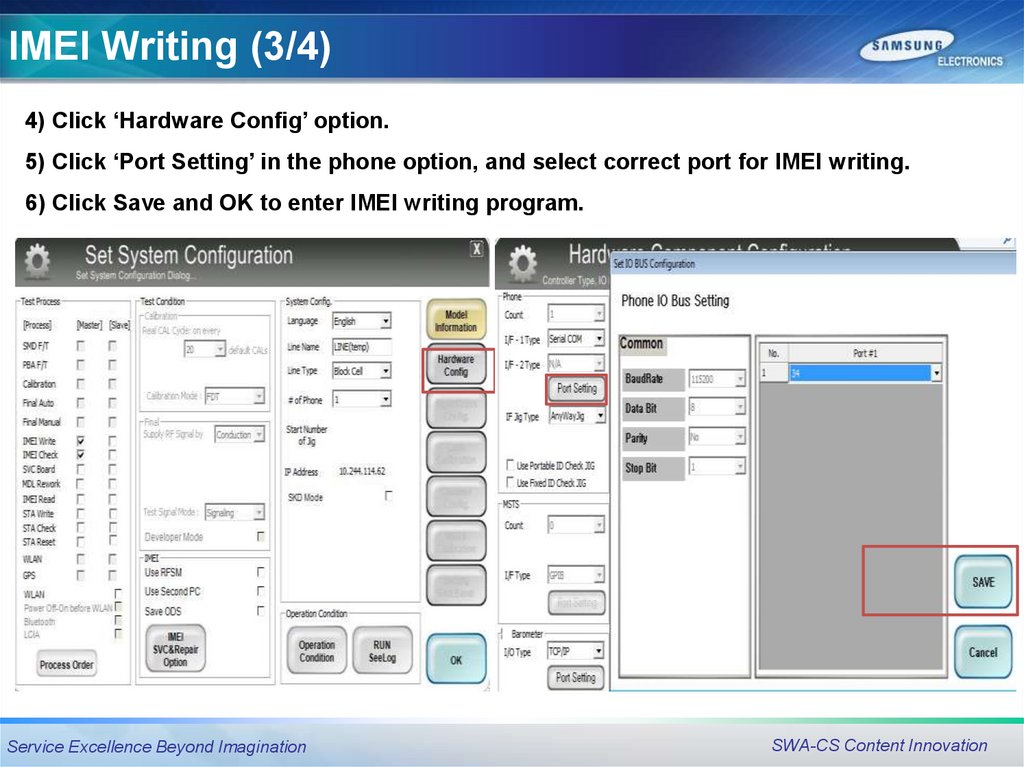
IMEI Writing (3/4)4) Click ‘Hardware Config’ option.
5) Click ‘Port Setting’ in the phone option, and select correct port for IMEI writing.
6) Click Save and OK to enter IMEI writing program.
Service Excellence Beyond Imagination
SWA-CS Content Innovation
12.
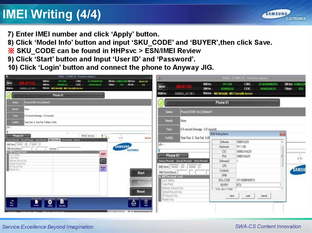
IMEI Writing (4/4)7) Enter IMEI number and click ‘Apply’ button.
8) Click ‘Model Info’ button and input ‘SKU_CODE’ and ‘BUYER’,then click Save.
※ SKU_CODE can be found in HHPsvc > ESN/IMEI Review
9) Click ‘Start’ button and Input ‘User ID’ and ‘Password’.
10) Click ‘Login’ button and connect the phone to Anyway JIG.
Service Excellence Beyond Imagination
SWA-CS Content Innovation
13.
Boot RecoveryEmergency download
mode & Odin T-Flash
mode
Service Excellence Beyond Imagination
SWA-CS Content Innovation
14.
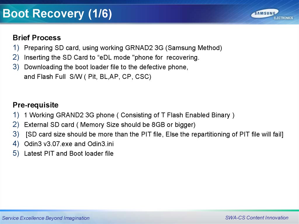
Boot Recovery (1/6)Brief Process
1) Preparing SD card, using working GRNAD2 3G (Samsung Method)
2) Inserting the SD Card to “eDL mode "phone for recovering.
3) Downloading the boot loader file to the defective phone,
and Flash Full S/W ( Pit, BL,AP, CP, CSC)
Pre-requisite
1) 1 Working GRAND2 3G phone ( Consisting of T Flash Enabled Binary )
2) External SD card ( Memory Size should be 8GB or bigger)
3) [SD card size should be more than the PIT file, Else the repartitioning of PIT file will fail]
4) Odin3 v3.07.exe and Odin3.ini
5) Latest PIT and Boot loader file
Service Excellence Beyond Imagination
SWA-CS Content Innovation
15.
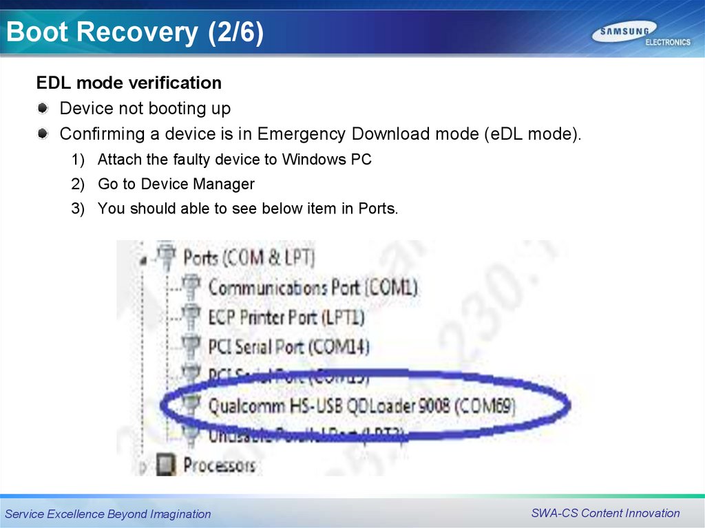
Boot Recovery (2/6)EDL mode verification
Device not booting up
Confirming a device is in Emergency Download mode (eDL mode).
1) Attach the faulty device to Windows PC
2) Go to Device Manager
3) You should able to see below item in Ports.
Service Excellence Beyond Imagination
SWA-CS Content Innovation
16.
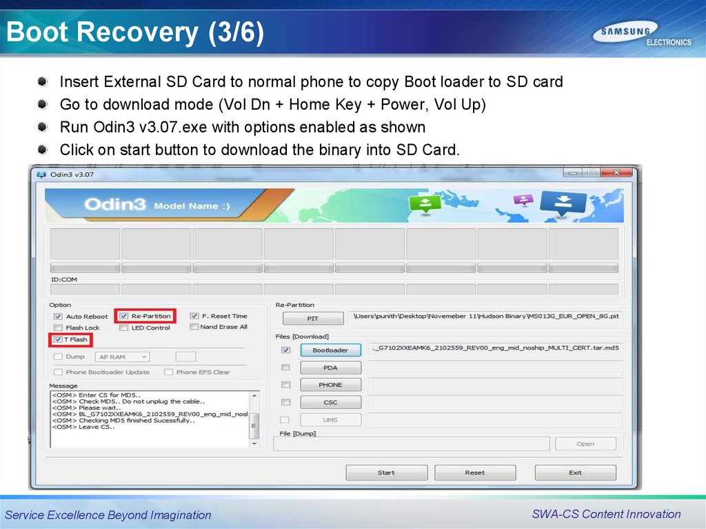
Boot Recovery (3/6)Insert External SD Card to normal phone to copy Boot loader to SD card
Go to download mode (Vol Dn + Home Key + Power, Vol Up)
Run Odin3 v3.07.exe with options enabled as shown
Click on start button to download the binary into SD Card.
Service Excellence Beyond Imagination
SWA-CS Content Innovation
17.
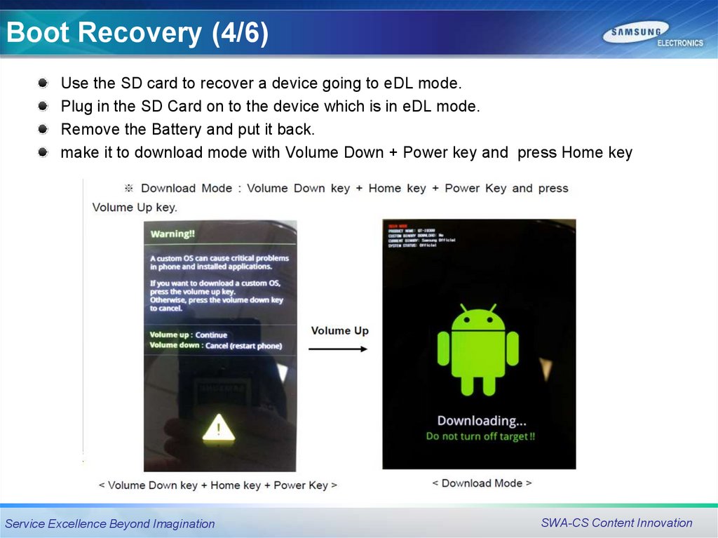
Boot Recovery (4/6)Use the SD card to recover a device going to eDL mode.
Plug in the SD Card on to the device which is in eDL mode.
Remove the Battery and put it back.
make it to download mode with Volume Down + Power key and press Home key
Service Excellence Beyond Imagination
SWA-CS Content Innovation
18.
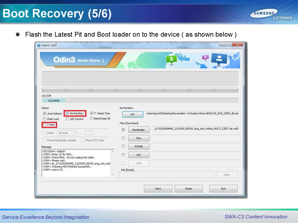
Boot Recovery (5/6)Flash the Latest Pit and Boot loader on to the device ( as shown below )
Service Excellence Beyond Imagination
SWA-CS Content Innovation
19.
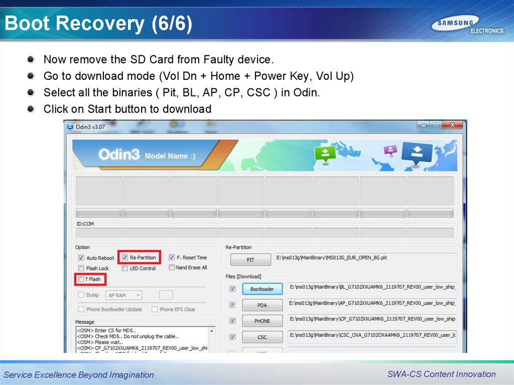
Boot Recovery (6/6)Now remove the SD Card from Faulty device.
Go to download mode (Vol Dn + Home + Power Key, Vol Up)
Select all the binaries ( Pit, BL, AP, CP, CSC ) in Odin.
Click on Start button to download
Service Excellence Beyond Imagination
SWA-CS Content Innovation
20.
Disassembly & Assembly InstructionDisassembly & Assembly
Instruction
Service Excellence Beyond Imagination
SWA-CS Content Innovation
21.
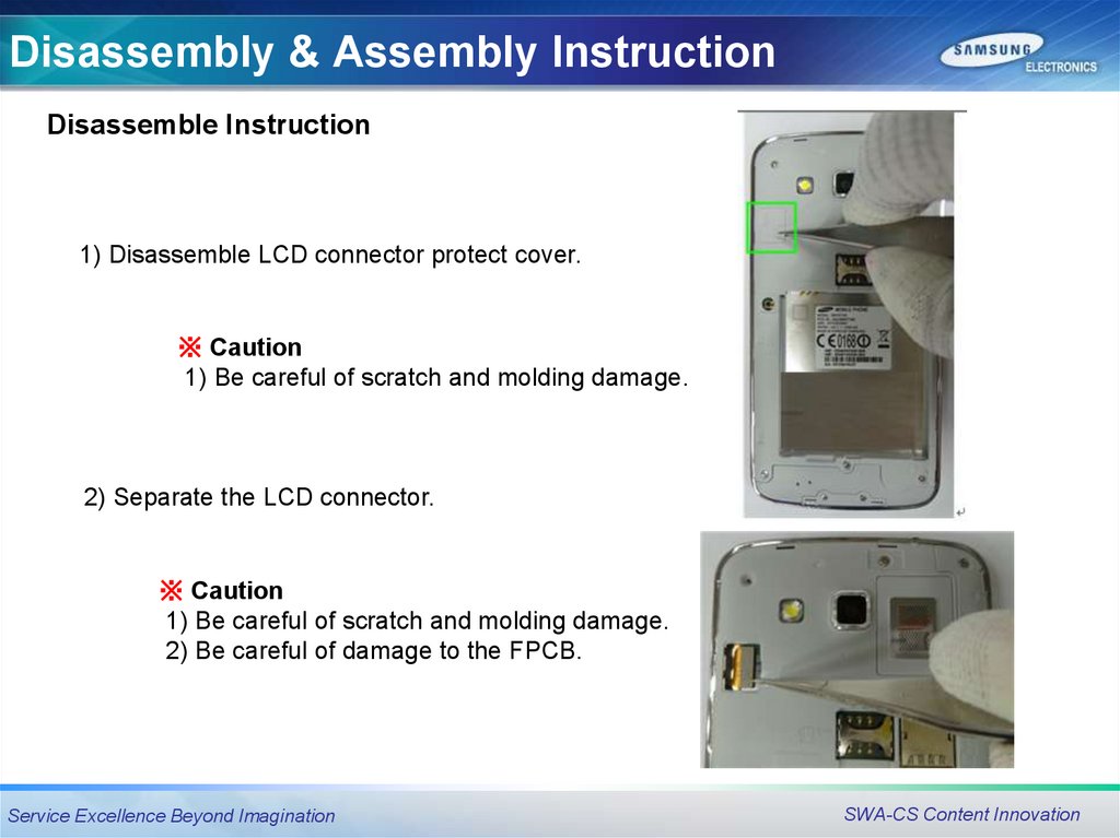
Disassembly & Assembly InstructionDisassemble Instruction
1) Disassemble LCD connector protect cover.
※ Caution
1) Be careful of scratch and molding damage.
2) Separate the LCD connector.
※ Caution
1) Be careful of scratch and molding damage.
2) Be careful of damage to the FPCB.
Service Excellence Beyond Imagination
SWA-CS Content Innovation
22.
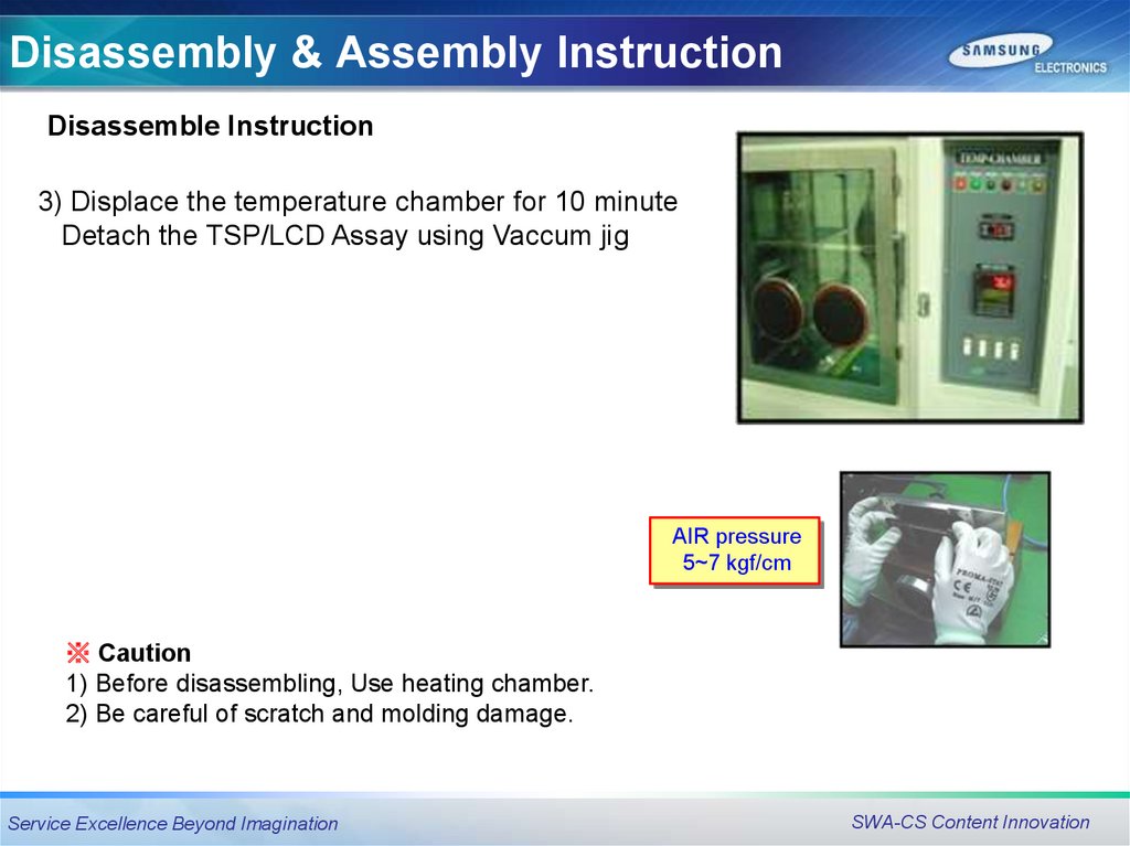
Disassembly & Assembly InstructionDisassemble Instruction
3) Displace the temperature chamber for 10 minute
Detach the TSP/LCD Assay using Vaccum jig
AIR pressure
5~7 kgf/cm
※ Caution
1) Before disassembling, Use heating chamber.
2) Be careful of scratch and molding damage.
Service Excellence Beyond Imagination
SWA-CS Content Innovation
23.
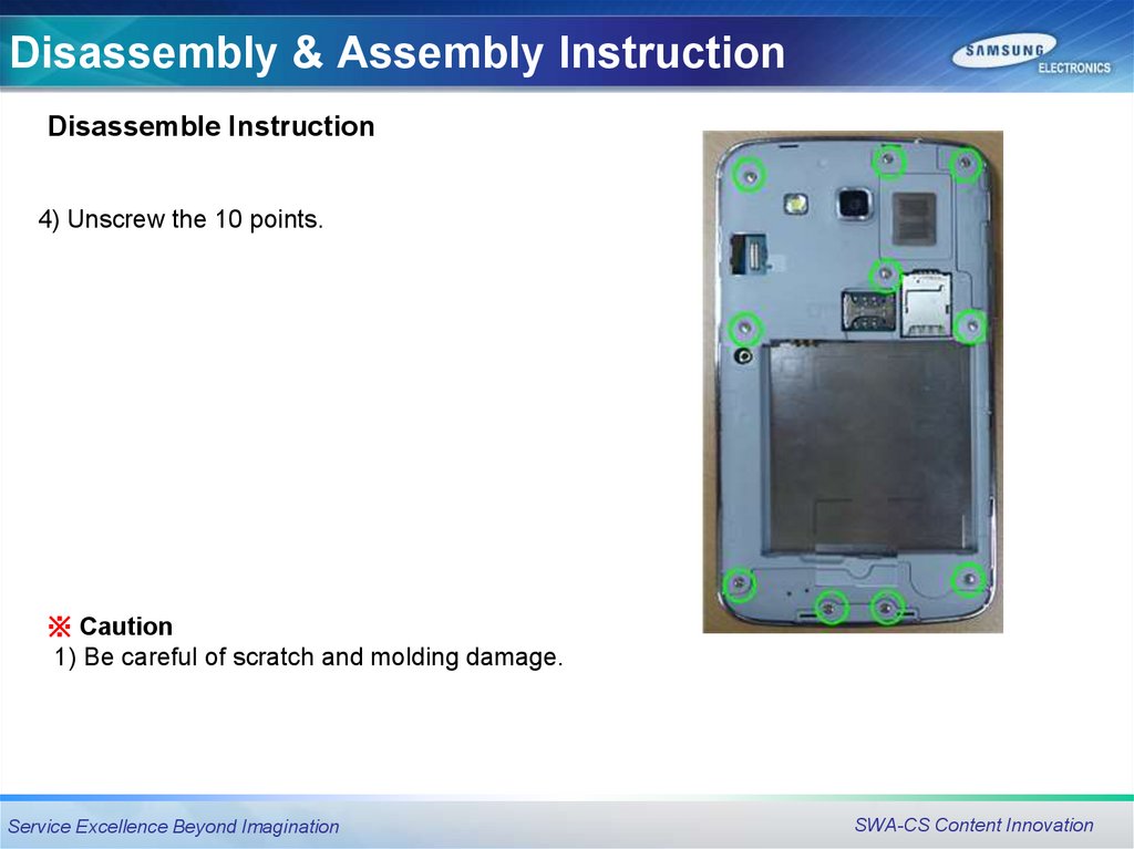
Disassembly & Assembly InstructionDisassemble Instruction
4) Unscrew the 10 points.
※ Caution
1) Be careful of scratch and molding damage.
Service Excellence Beyond Imagination
SWA-CS Content Innovation
24.
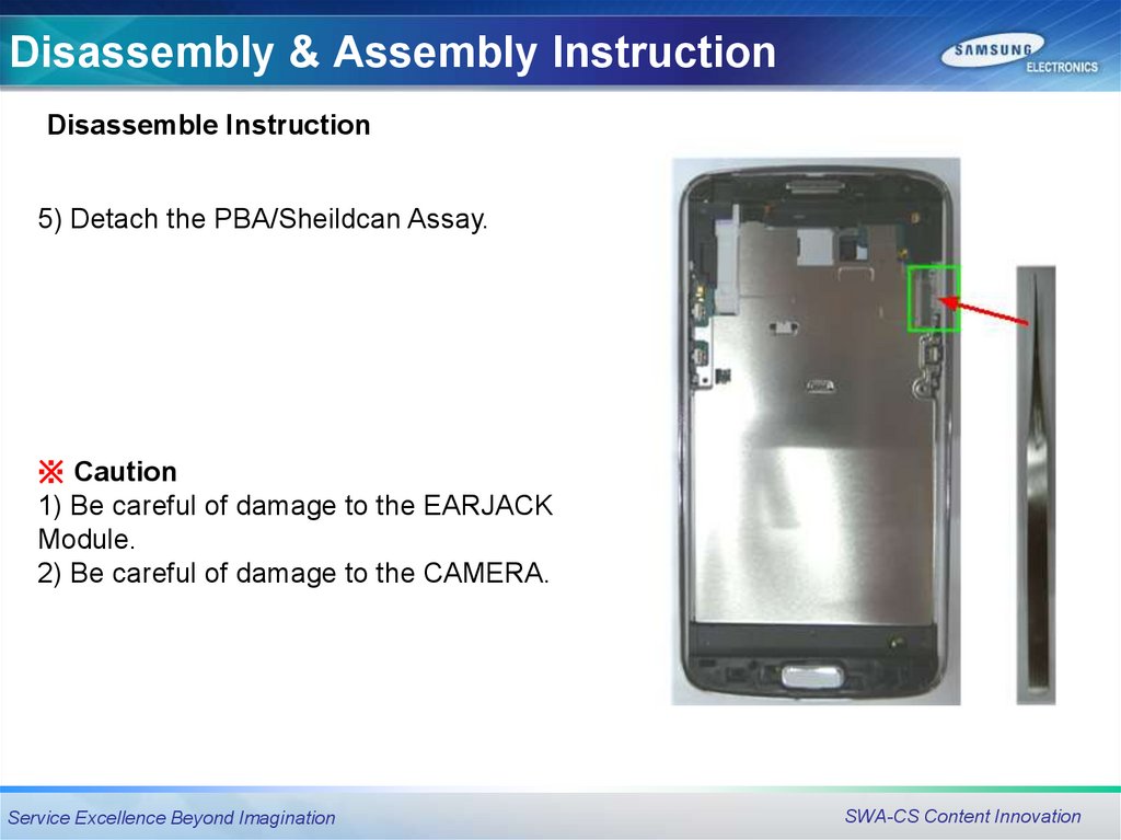
Disassembly & Assembly InstructionDisassemble Instruction
5) Detach the PBA/Sheildcan Assay.
※ Caution
1) Be careful of damage to the EARJACK
Module.
2) Be careful of damage to the CAMERA.
Service Excellence Beyond Imagination
SWA-CS Content Innovation
25.
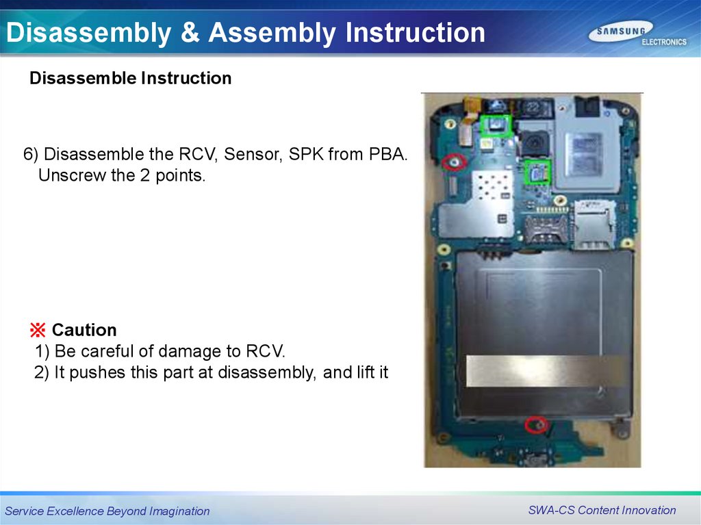
Disassembly & Assembly InstructionDisassemble Instruction
6) Disassemble the RCV, Sensor, SPK from PBA.
Unscrew the 2 points.
※ Caution
1) Be careful of damage to RCV.
2) It pushes this part at disassembly, and lift it
Service Excellence Beyond Imagination
SWA-CS Content Innovation
26.
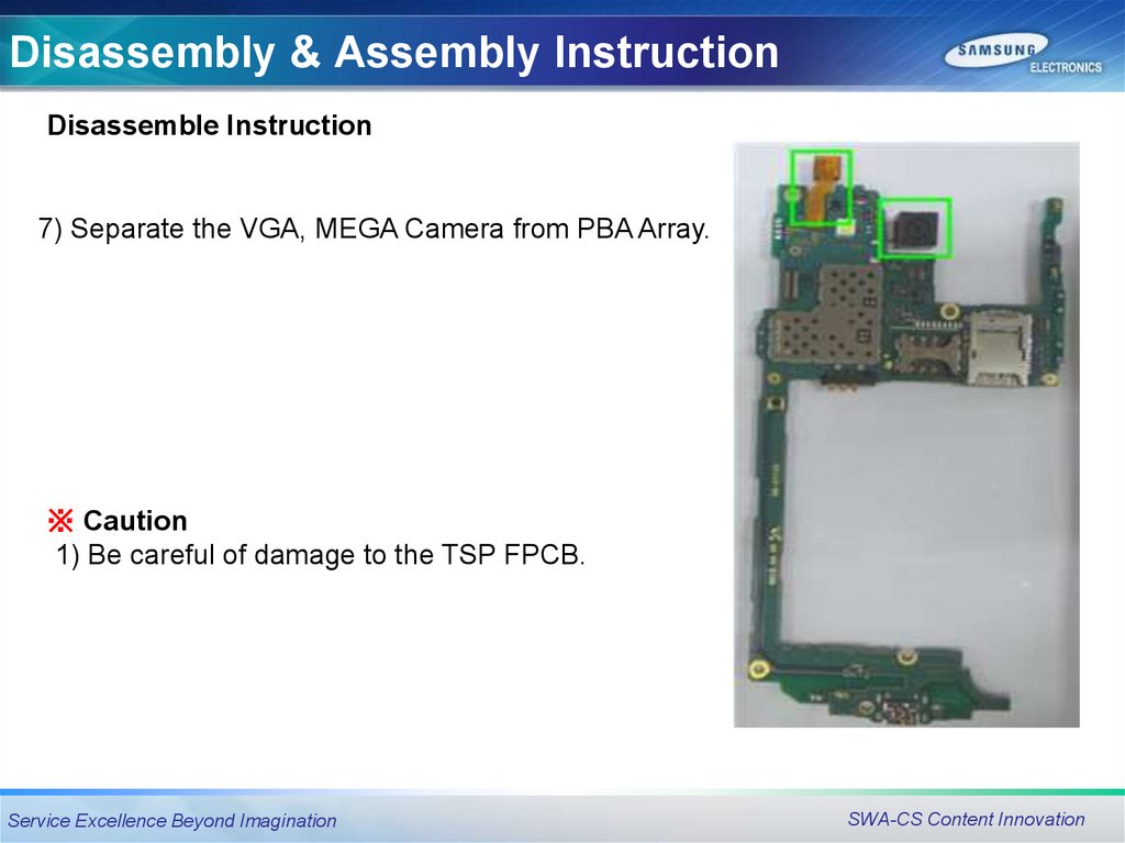
Disassembly & Assembly InstructionDisassemble Instruction
7) Separate the VGA, MEGA Camera from PBA Array.
※ Caution
1) Be careful of damage to the TSP FPCB.
Service Excellence Beyond Imagination
SWA-CS Content Innovation
27.
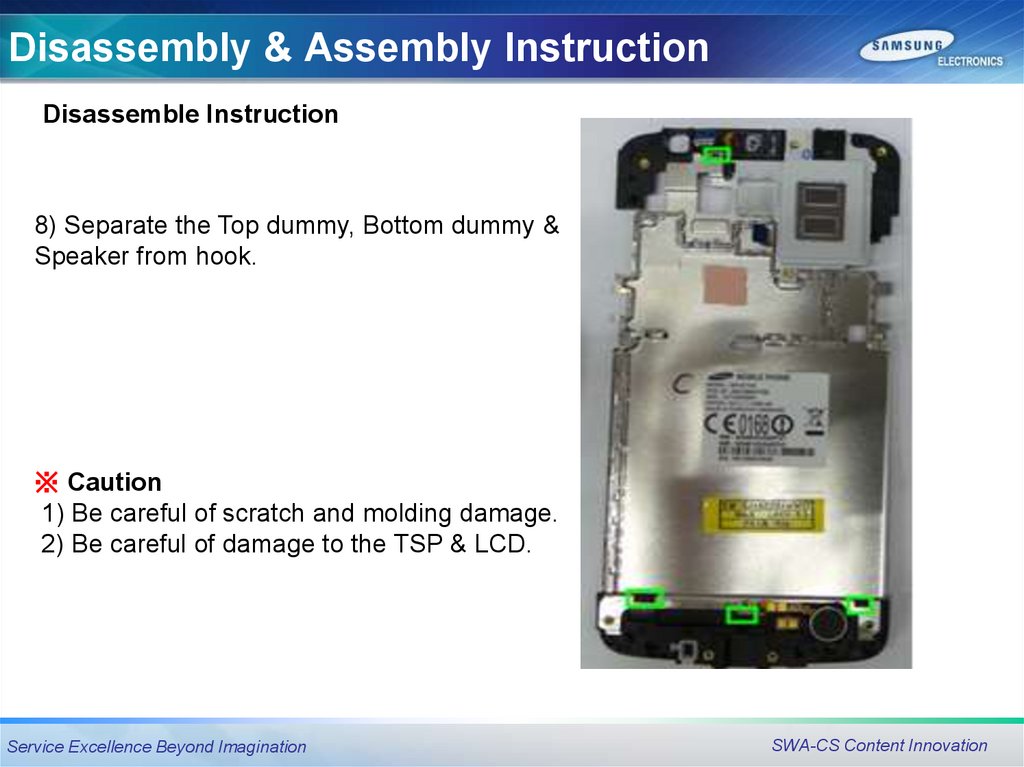
Disassembly & Assembly InstructionDisassemble Instruction
8) Separate the Top dummy, Bottom dummy &
Speaker from hook.
※ Caution
1) Be careful of scratch and molding damage.
2) Be careful of damage to the TSP & LCD.
Service Excellence Beyond Imagination
SWA-CS Content Innovation
28.
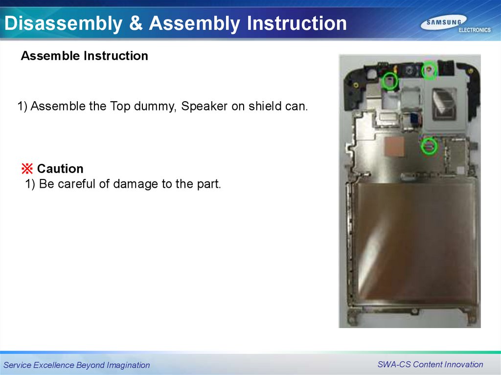
Disassembly & Assembly InstructionAssemble Instruction
1) Assemble the Top dummy, Speaker on shield can.
※ Caution
1) Be careful of damage to the part.
Service Excellence Beyond Imagination
SWA-CS Content Innovation
29.
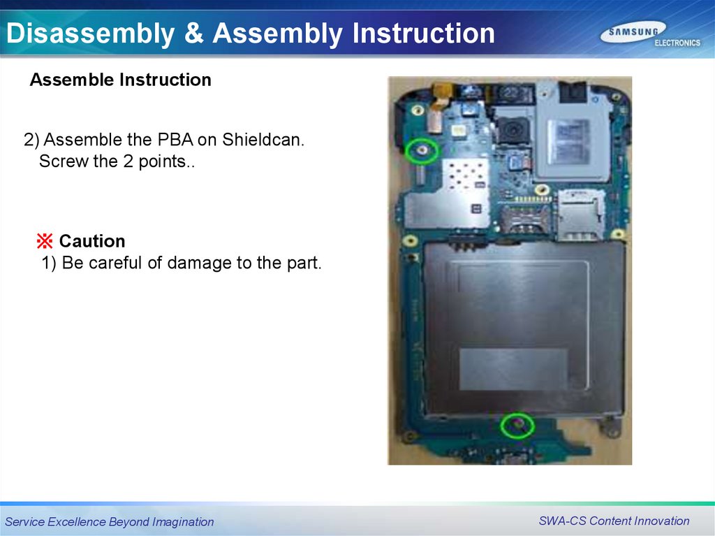
Disassembly & Assembly InstructionAssemble Instruction
2) Assemble the PBA on Shieldcan.
Screw the 2 points..
※ Caution
1) Be careful of damage to the part.
Service Excellence Beyond Imagination
SWA-CS Content Innovation
30.
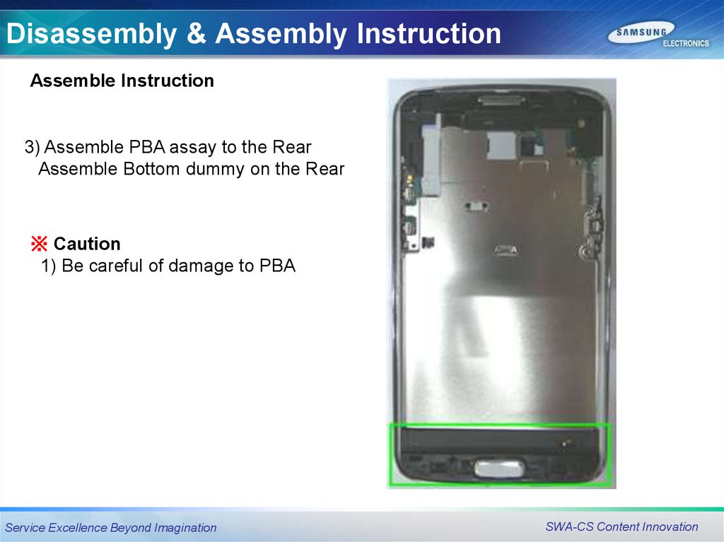
Disassembly & Assembly InstructionAssemble Instruction
3) Assemble PBA assay to the Rear
Assemble Bottom dummy on the Rear
※ Caution
1) Be careful of damage to PBA
Service Excellence Beyond Imagination
SWA-CS Content Innovation
31.
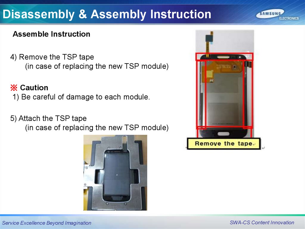
Disassembly & Assembly InstructionAssemble Instruction
4) Remove the TSP tape
(in case of replacing the new TSP module)
※ Caution
1) Be careful of damage to each module.
5) Attach the TSP tape
(in case of replacing the new TSP module)
Service Excellence Beyond Imagination
SWA-CS Content Innovation
32.
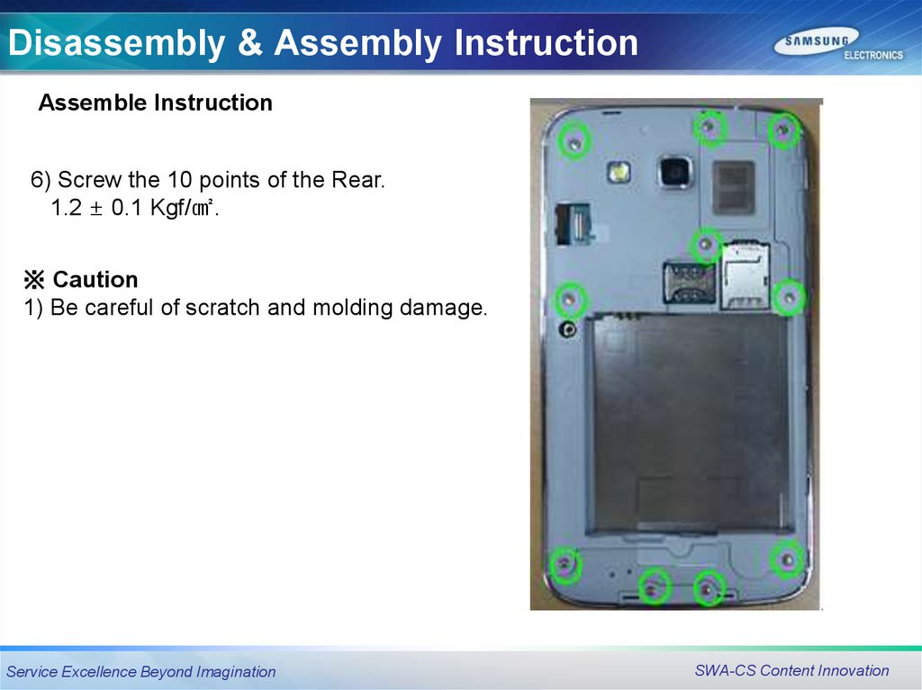
Disassembly & Assembly InstructionAssemble Instruction
6) Screw the 10 points of the Rear.
1.2 ± 0.1 Kgf/㎠.
※ Caution
1) Be careful of scratch and molding damage.
Service Excellence Beyond Imagination
SWA-CS Content Innovation
33.
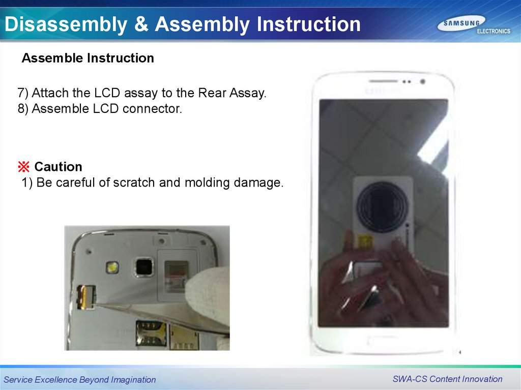
Disassembly & Assembly InstructionAssemble Instruction
7) Attach the LCD assay to the Rear Assay.
8) Assemble LCD connector.
※ Caution
1) Be careful of scratch and molding damage.
Service Excellence Beyond Imagination
SWA-CS Content Innovation
34.
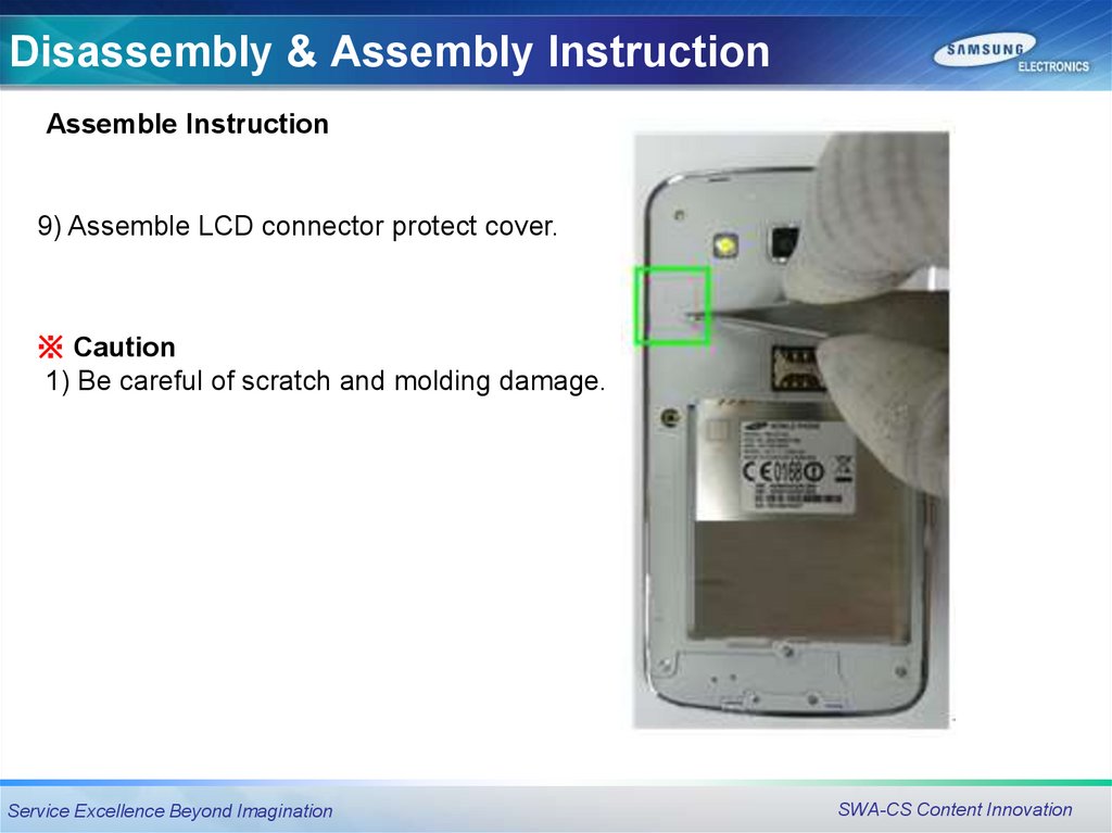
Disassembly & Assembly InstructionAssemble Instruction
9) Assemble LCD connector protect cover.
※ Caution
1) Be careful of scratch and molding damage.
Service Excellence Beyond Imagination
SWA-CS Content Innovation
35.
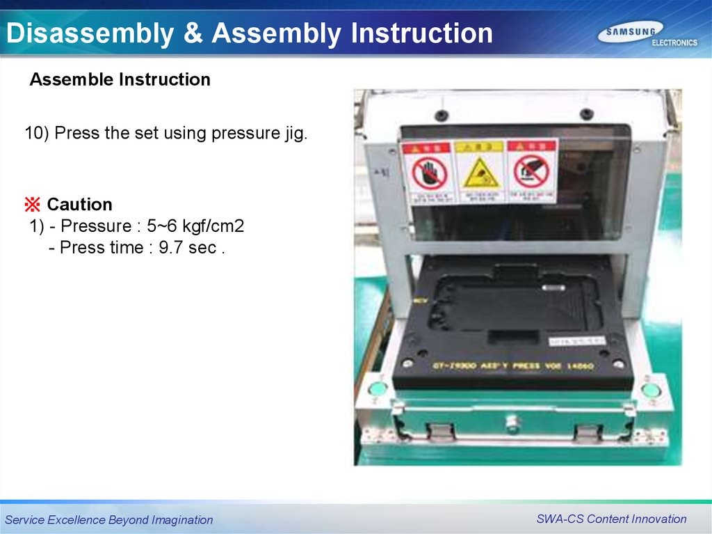
Disassembly & Assembly InstructionAssemble Instruction
10) Press the set using pressure jig.
※ Caution
1) - Pressure : 5~6 kgf/cm2
- Press time : 9.7 sec .
Service Excellence Beyond Imagination
SWA-CS Content Innovation
36.
Electronic ComponentsElectronic
Components
Service Excellence Beyond Imagination
SWA-CS Content Innovation
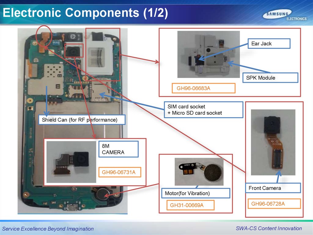
37.
Electronic Components (1/2)Ear Jack
SPK Module
GH96-06683A
SIM card socket
+ Micro SD card socket
Shield Can (for RF performance)
8M
CAMERA
GH96-06731A
Front Camera
Motor(for Vibration)
GH31-00669A
Service Excellence Beyond Imagination
GH96-06728A
SWA-CS Content Innovation
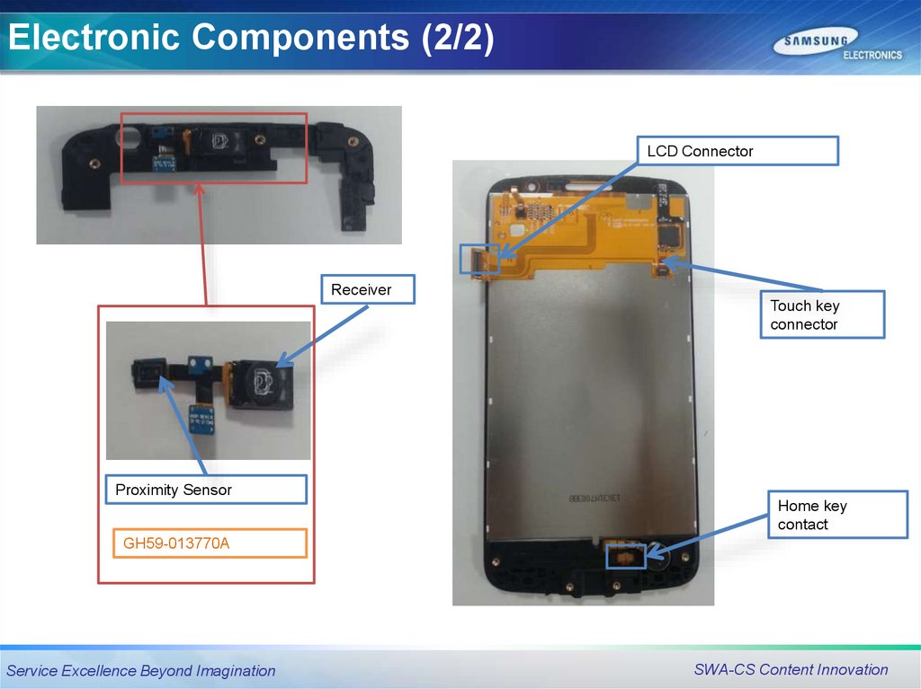
38.
Electronic Components (2/2)LCD Connector
Receiver
Touch key
connector
Proximity Sensor
Home key
contact
GH59-013770A
Service Excellence Beyond Imagination
SWA-CS Content Innovation
39.
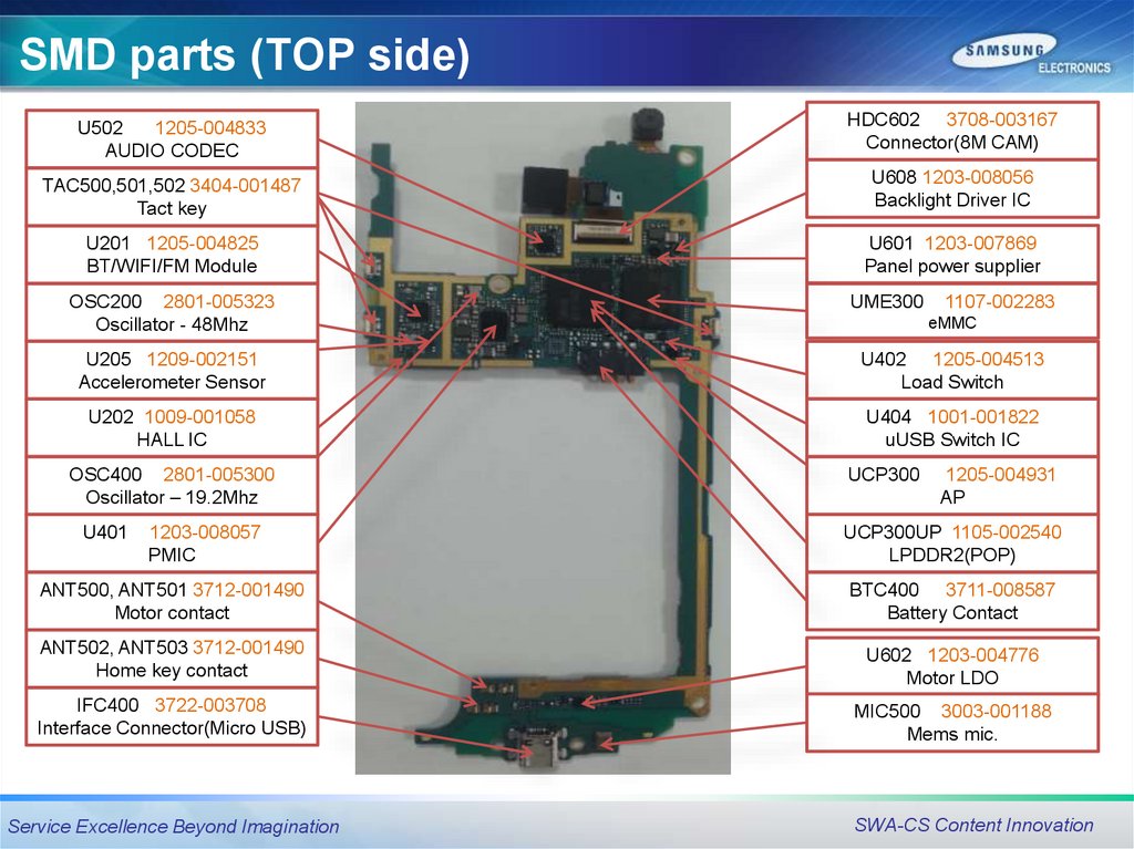
SMD parts (TOP side)U502
1205-004833
AUDIO CODEC
HDC602 3708-003167
Connector(8M CAM)
TAC500,501,502 3404-001487
Tact key
U608 1203-008056
Backlight Driver IC
U201 1205-004825
BT/WIFI/FM Module
U601 1203-007869
Panel power supplier
OSC200 2801-005323
Oscillator - 48Mhz
UME300
1107-002283
eMMC
U205 1209-002151
Accelerometer Sensor
U402 1205-004513
Load Switch
U202 1009-001058
HALL IC
U404 1001-001822
uUSB Switch IC
OSC400 2801-005300
Oscillator – 19.2Mhz
U401
1203-008057
PMIC
UCP300
1205-004931
AP
UCP300UP 1105-002540
LPDDR2(POP)
ANT500, ANT501 3712-001490
Motor contact
BTC400 3711-008587
Battery Contact
ANT502, ANT503 3712-001490
Home key contact
U602 1203-004776
Motor LDO
IFC400 3722-003708
Interface Connector(Micro USB)
MIC500 3003-001188
Mems mic.
Service Excellence Beyond Imagination
SWA-CS Content Innovation
40.
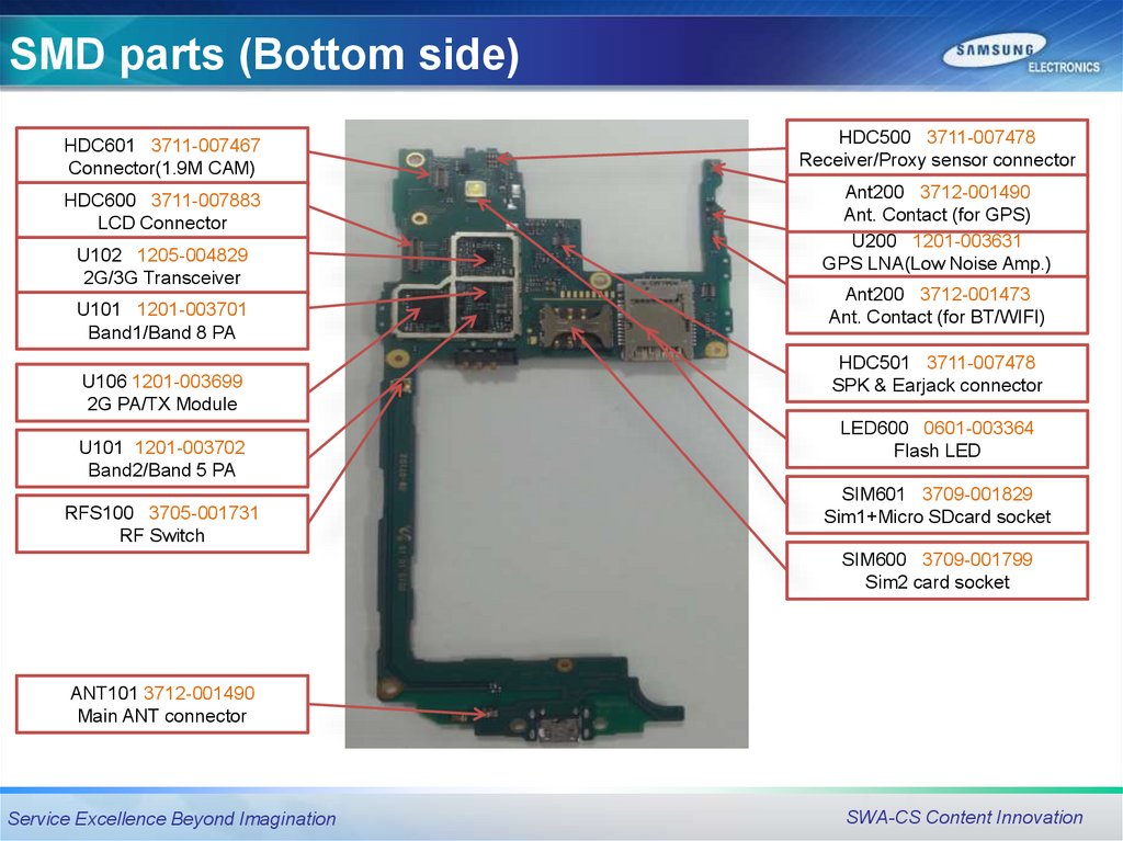
SMD parts (Bottom side)HDC601 3711-007467
Connector(1.9M CAM)
HDC500 3711-007478
Receiver/Proxy sensor connector
HDC600 3711-007883
LCD Connector
Ant200 3712-001490
Ant. Contact (for GPS)
U200 1201-003631
GPS LNA(Low Noise Amp.)
U102 1205-004829
2G/3G Transceiver
U101 1201-003701
Band1/Band 8 PA
U106 1201-003699
2G PA/TX Module
U101 1201-003702
Band2/Band 5 PA
RFS100 3705-001731
RF Switch
Ant200 3712-001473
Ant. Contact (for BT/WIFI)
HDC501 3711-007478
SPK & Earjack connector
LED600 0601-003364
Flash LED
SIM601 3709-001829
Sim1+Micro SDcard socket
SIM600 3709-001799
Sim2 card socket
ANT101 3712-001490
Main ANT connector
Service Excellence Beyond Imagination
SWA-CS Content Innovation
41.
TroubleshootingTroubleshooting
Service Excellence Beyond Imagination
SWA-CS Content Innovation
42.
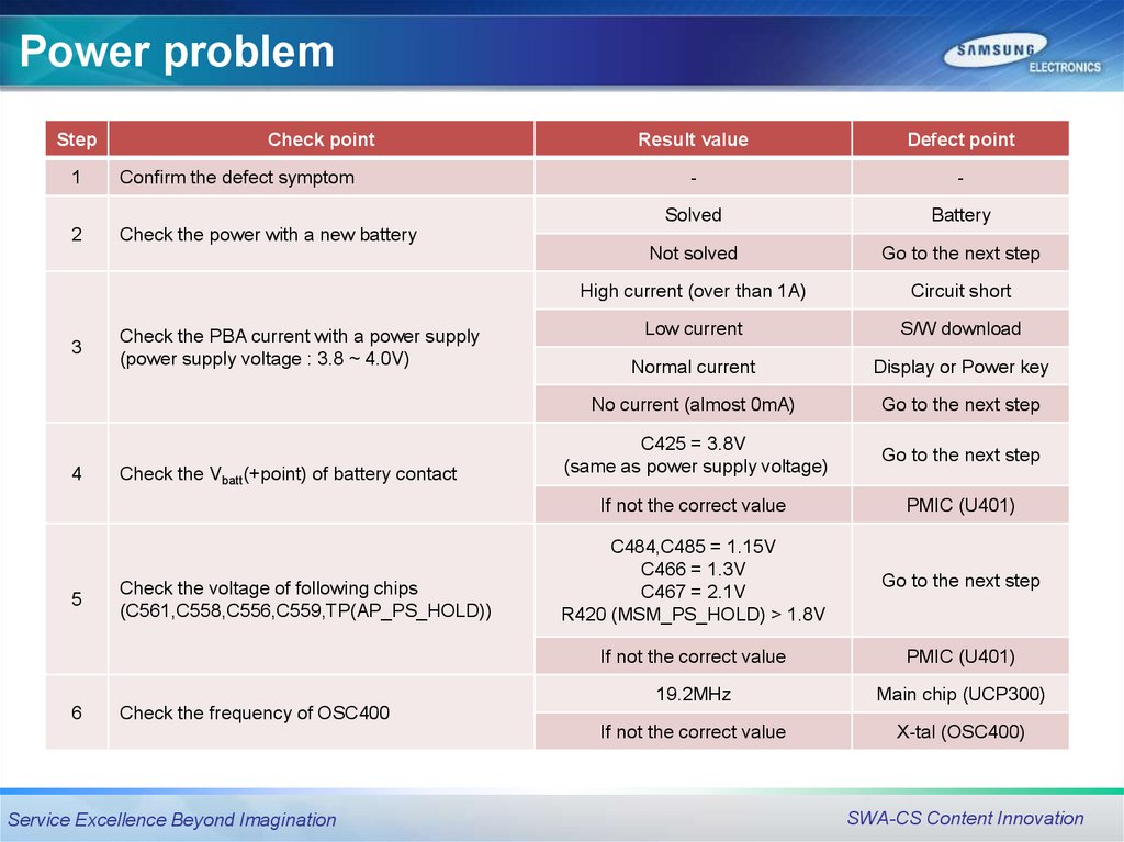
Power problemStep
Check point
1
Confirm the defect symptom
2
Check the power with a new battery
3
4
5
6
Check the PBA current with a power supply
(power supply voltage : 3.8 ~ 4.0V)
Check the Vbatt(+point) of battery contact
Check the voltage of following chips
(C561,C558,C556,C559,TP(AP_PS_HOLD))
Result value
Defect point
-
-
Solved
Battery
Not solved
Go to the next step
High current (over than 1A)
Circuit short
Low current
S/W download
Normal current
Display or Power key
No current (almost 0mA)
Go to the next step
C425 = 3.8V
(same as power supply voltage)
Go to the next step
If not the correct value
PMIC (U401)
C484,C485 = 1.15V
C466 = 1.3V
C467 = 2.1V
R420 (MSM_PS_HOLD) > 1.8V
Go to the next step
If not the correct value
PMIC (U401)
19.2MHz
Main chip (UCP300)
If not the correct value
X-tal (OSC400)
Check the frequency of OSC400
Service Excellence Beyond Imagination
SWA-CS Content Innovation
43.
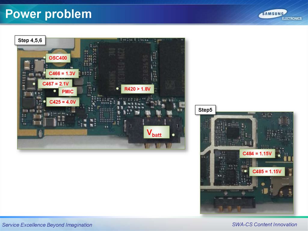
Power problemStep 4,5,6
OSC400
C466 = 1.3V
C467 = 2.1V
PMIC
R420 > 1.8V
C425 = 4.0V
Step5
Vbatt
C484 = 1.15V
C485 = 1.15V
Service Excellence Beyond Imagination
SWA-CS Content Innovation
44.
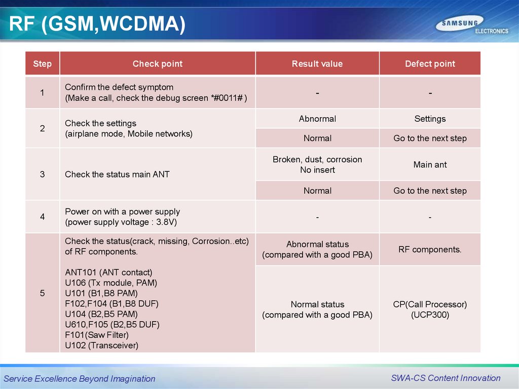
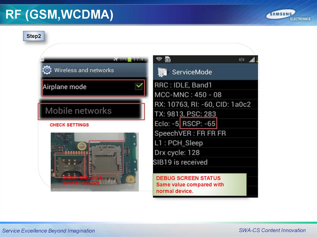
RF (GSM,WCDMA)Step
Check point
Result value
Defect point
1
Confirm the defect symptom
(Make a call, check the debug screen *#0011# )
-
-
Check the settings
(airplane mode, Mobile networks)
Abnormal
Settings
2
Normal
Go to the next step
Broken, dust, corrosion
No insert
Main ant
Normal
Go to the next step
-
-
Check the status(crack, missing, Corrosion..etc)
of RF components.
Abnormal status
(compared with a good PBA)
RF components.
ANT101 (ANT contact)
U106 (Tx module, PAM)
U101 (B1,B8 PAM)
F102,F104 (B1,B8 DUF)
U104 (B2,B5 PAM)
U610,F105 (B2,B5 DUF)
F101(Saw Filter)
U102 (Transceiver)
Normal status
(compared with a good PBA)
CP(Call Processor)
(UCP300)
3
4
5
Check the status main ANT
Power on with a power supply
(power supply voltage : 3.8V)
Service Excellence Beyond Imagination
SWA-CS Content Innovation
45.
RF (GSM,WCDMA)Step2
CHECK SETTINGS
CHECK SIM card &
SOCKET STATUS
Service Excellence Beyond Imagination
DEBUG SCREEN STATUS
Same value compared with
normal device.
SWA-CS Content Innovation
46.
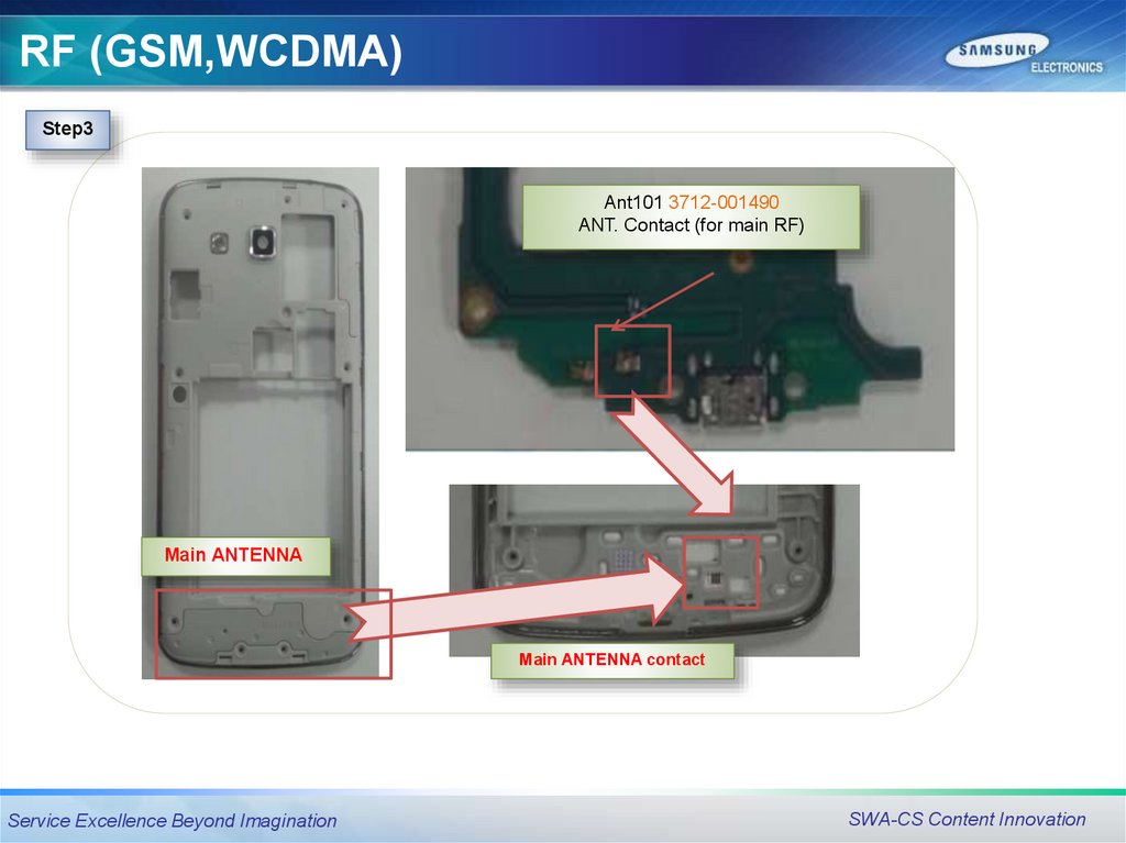
RF (GSM,WCDMA)Step3
Ant101 3712-001490
ANT. Contact (for main RF)
Main ANTENNA
Main ANTENNA contact
Service Excellence Beyond Imagination
SWA-CS Content Innovation
47.
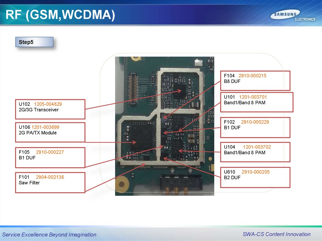
RF (GSM,WCDMA)Step5
F104 2910-000215
B8 DUF
U102 1205-004829
2G/3G Transceiver
U106 1201-003699
2G PA/TX Module
F105 2910-000227
B1 DUF
F101 2904-002136
Saw Filter
Service Excellence Beyond Imagination
U101 1201-003701
Band1/Band 8 PAM
F102 2910-000229
B1 DUF
U104
1201-003702
Band1/Band 8 PAM
U610 2910-000205
B2 DUF
SWA-CS Content Innovation
48.
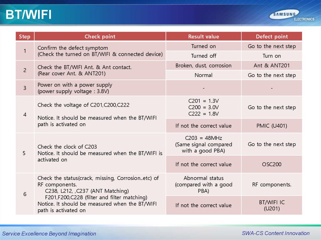
BT/WIFIStep
Check point
Result value
Defect point
1
Confirm the defect symptom
(Check the turned on BT/WIFI & connected device)
Turned on
Go to the next step
Turned off
Turn on
2
Check the BT/WIFI Ant. & Ant contact.
(Rear cover Ant. & ANT201)
Broken, dust, corrosion
Ant & ANT201
Normal
Go to the next step
3
Power on with a power supply
(power supply voltage : 3.8V)
-
-
C201 = 1.3V
C200 = 3.0V
C222 = 1.8V
Go to the next step
If not the correct value
PMIC (U401)
C203 = 48MHz
(Same signal compared
with a good PBA)
Go to the next step
If not the correct value
OSC200
Abnormal status
(compared with a good
PBA)
RF components.
If not the correct value
BT/WIFI IC
(U201)
Check the voltage of C201,C200,C222
4
5
6
Notice. It should be measured when the BT/WIFI
path is activated on
Check the clock of C203
Notice. It should be measured when the BT/WIFI is
activated on
Check the status(crack, missing, Corrosion..etc) of
RF components.
C238, L212, ,C237 (ANT Matching)
F201,F200,C228 (filter and filter matching)
Notice. It should be measured when the BT/WIFI
path is activated on
Service Excellence Beyond Imagination
SWA-CS Content Innovation
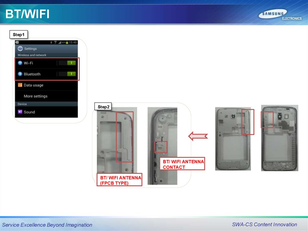
49.
BT/WIFIStep1
Step2
BT/ WIFI ANTENNA
CONTACT
BT/ WIFI ANTENNA
(FPCB TYPE)
Service Excellence Beyond Imagination
SWA-CS Content Innovation
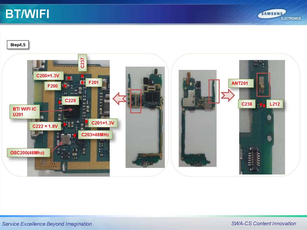
50.
BT/WIFIC237
Step4,5
C200=1.3V
F201
F200
C228
ANT201
C238
L212
BT/ WIFI IC
U201
C222 = 1.8V
C201=1.3V
C203=48MHz
OSC200(48Mhz)
Service Excellence Beyond Imagination
SWA-CS Content Innovation
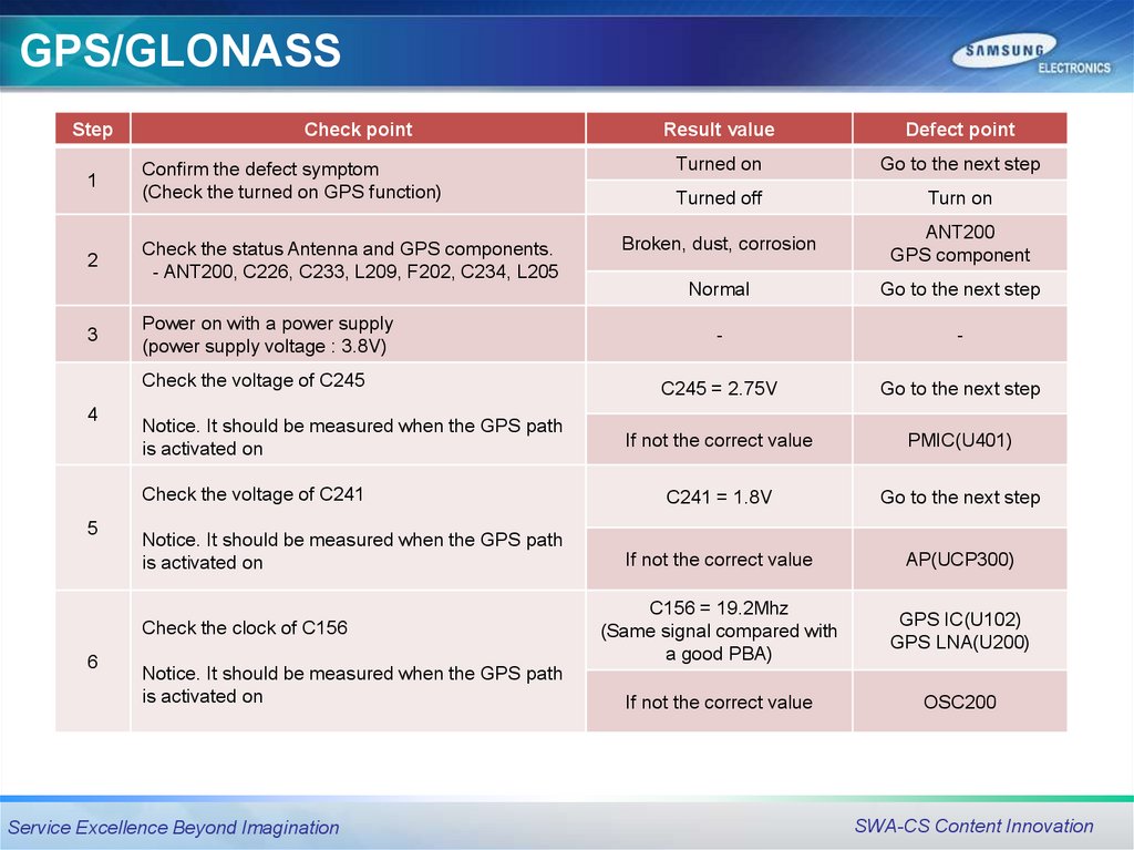
51.
GPS/GLONASSStep
Check point
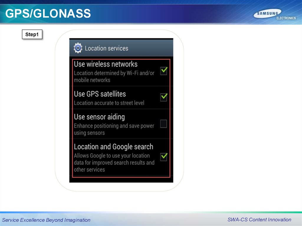
1
Confirm the defect symptom
(Check the turned on GPS function)
2
Check the status Antenna and GPS components.
- ANT200, C226, C233, L209, F202, C234, L205
3
Power on with a power supply
(power supply voltage : 3.8V)
Check the voltage of C245
4
Notice. It should be measured when the GPS path
is activated on
Check the voltage of C241
5
Notice. It should be measured when the GPS path
is activated on
Check the clock of C156
6
Notice. It should be measured when the GPS path
is activated on
Service Excellence Beyond Imagination
Result value
Defect point
Turned on
Go to the next step
Turned off
Turn on
Broken, dust, corrosion
ANT200
GPS component
Normal
Go to the next step
-
-
C245 = 2.75V
Go to the next step
If not the correct value
PMIC(U401)
C241 = 1.8V
Go to the next step
If not the correct value
AP(UCP300)
C156 = 19.2Mhz
(Same signal compared with
a good PBA)
GPS IC(U102)
GPS LNA(U200)
If not the correct value
OSC200
SWA-CS Content Innovation
52.
GPS/GLONASSStep1
Service Excellence Beyond Imagination
SWA-CS Content Innovation
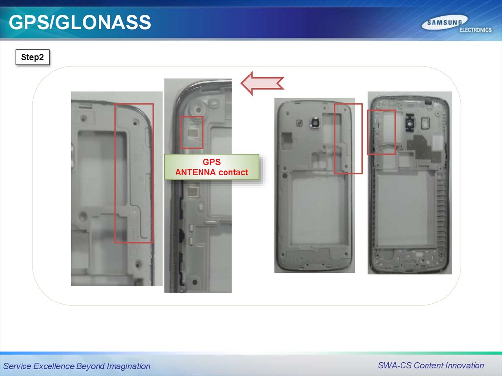
53.
GPS/GLONASSStep2
GPS
ANTENNA contact
Service Excellence Beyond Imagination
SWA-CS Content Innovation
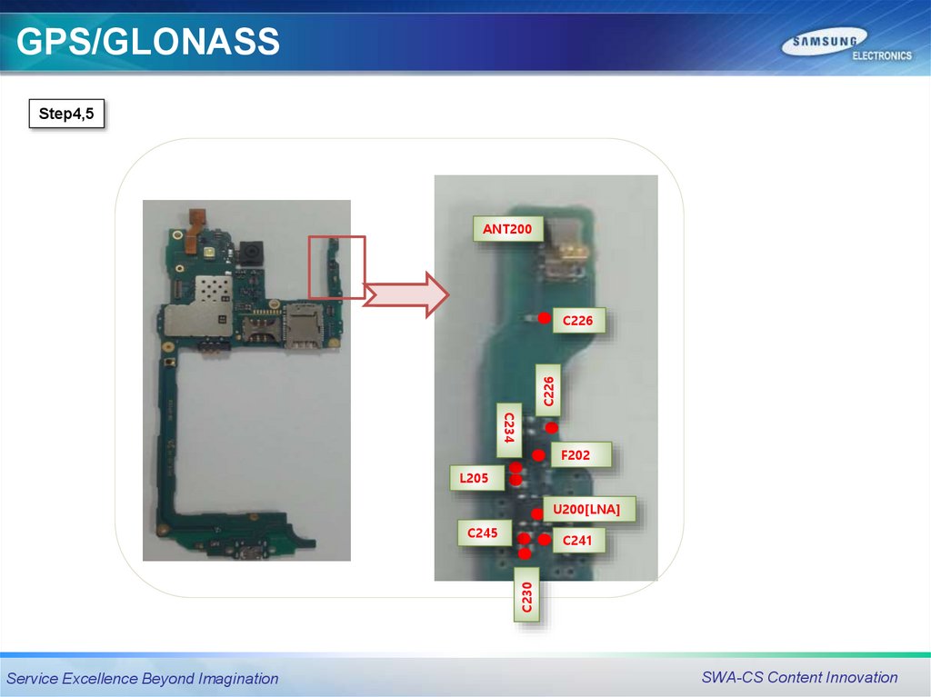
54.
GPS/GLONASSStep4,5
ANT200
C226
C226
C234
F202
L205
U200[LNA]
C245
C230
C241
Service Excellence Beyond Imagination
SWA-CS Content Innovation
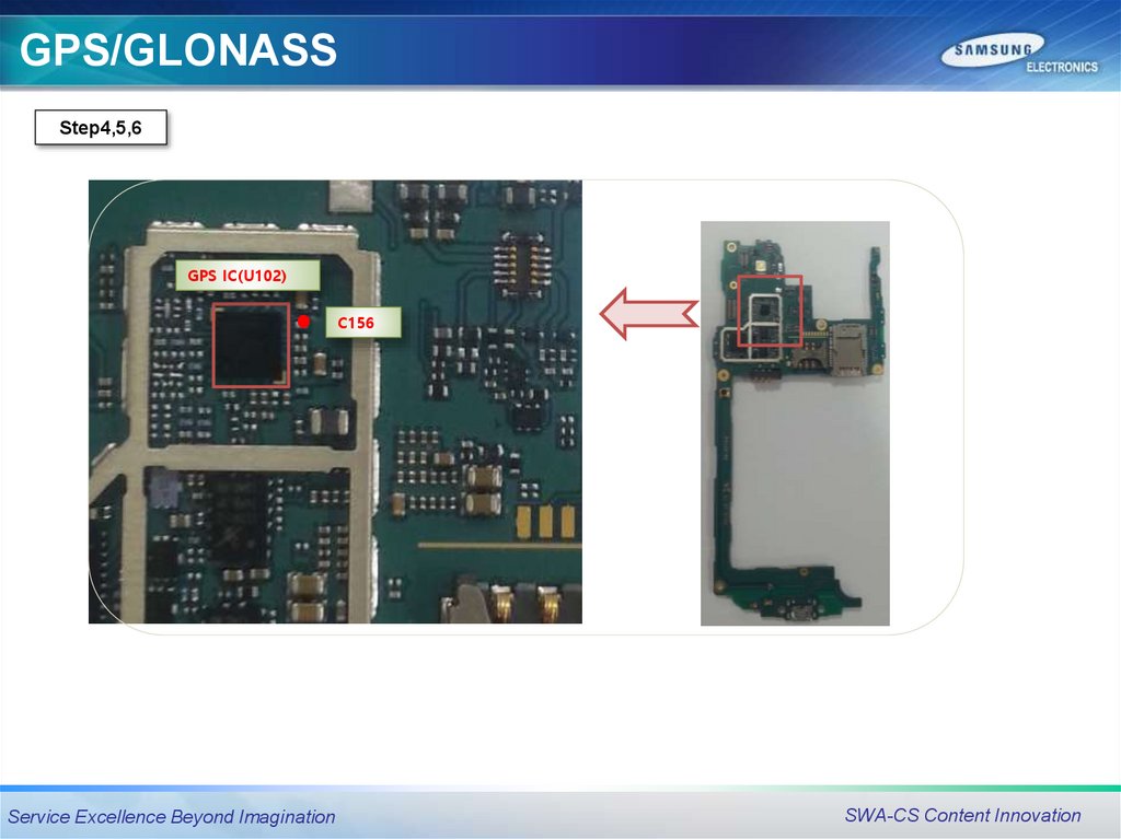
55.
GPS/GLONASSStep4,5,6
GPS IC(U102)
C156
Service Excellence Beyond Imagination
SWA-CS Content Innovation
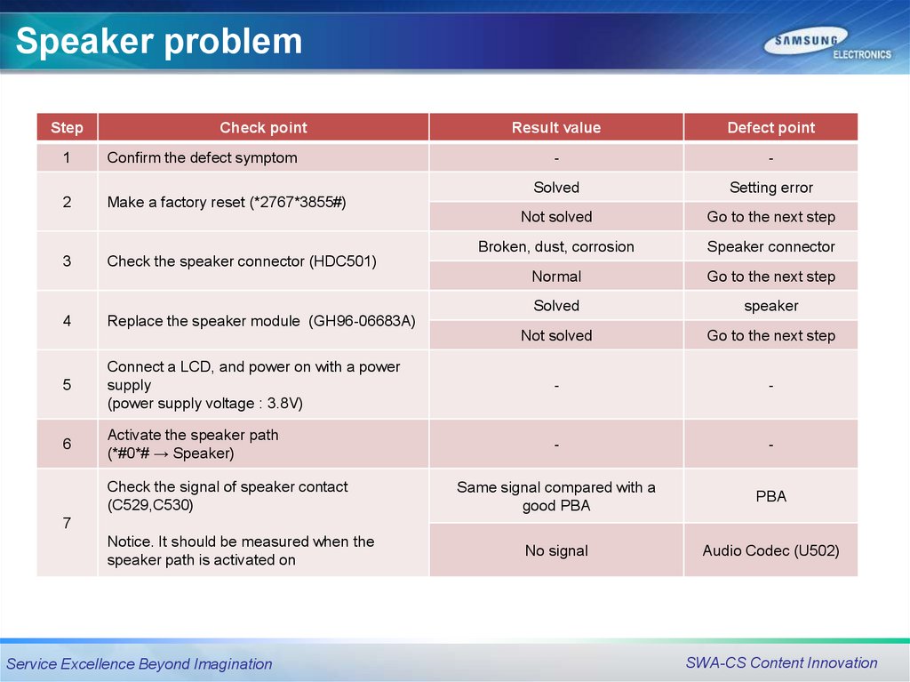
56.
Speaker problemStep
Check point
Result value
Defect point
-
-
Solved
Setting error
Not solved
Go to the next step
Broken, dust, corrosion
Speaker connector
Normal
Go to the next step
Solved
speaker
Not solved
Go to the next step
5
Connect a LCD, and power on with a power
supply
(power supply voltage : 3.8V)
-
-
6
Activate the speaker path
(*#0*# → Speaker)
-
-
Same signal compared with a
good PBA
PBA
No signal
Audio Codec (U502)
1
Confirm the defect symptom
2
Make a factory reset (*2767*3855#)
3
4
Check the speaker connector (HDC501)
Replace the speaker module (GH96-06683A)
Check the signal of speaker contact
(C529,C530)
7
Notice. It should be measured when the
speaker path is activated on
Service Excellence Beyond Imagination
SWA-CS Content Innovation
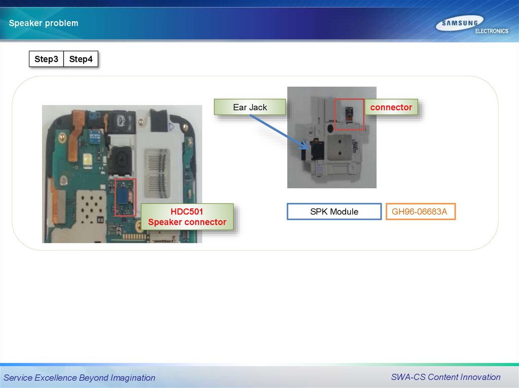
57.
Speaker problemStep3
Step4
Ear Jack
HDC501
Speaker connector
Service Excellence Beyond Imagination
connector
SPK Module
GH96-06683A
SWA-CS Content Innovation
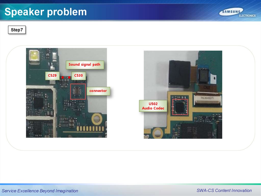
58.
Speaker problemStep7
Sound signal path
C529
C530
connector
U502
Audio Codec
Service Excellence Beyond Imagination
SWA-CS Content Innovation
59.
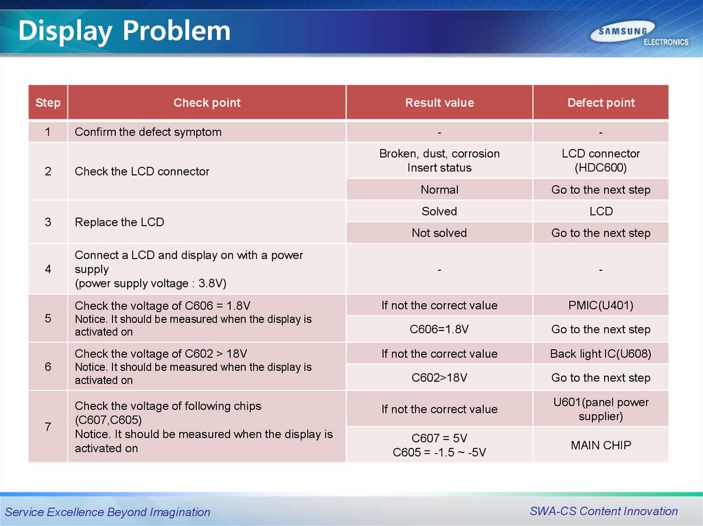
Display ProblemStep
1
2
Check point
Confirm the defect symptom
Check the LCD connector
3
Replace the LCD
4
Connect a LCD and display on with a power
supply
(power supply voltage : 3.8V)
Check the voltage of C606 = 1.8V
5
Notice. It should be measured when the display is
activated on
Check the voltage of C602 > 18V
6
7
Notice. It should be measured when the display is
activated on
Check the voltage of following chips
(C607,C605)
Notice. It should be measured when the display is
activated on
Service Excellence Beyond Imagination
Result value
Defect point
-
-
Broken, dust, corrosion
Insert status
LCD connector
(HDC600)
Normal
Go to the next step
Solved
LCD
Not solved
Go to the next step
-
-
If not the correct value
PMIC(U401)
C606=1.8V
Go to the next step
If not the correct value
Back light IC(U608)
C602>18V
Go to the next step
If not the correct value
U601(panel power
supplier)
C607 = 5V
C605 = -1.5 ~ -5V
MAIN CHIP
SWA-CS Content Innovation
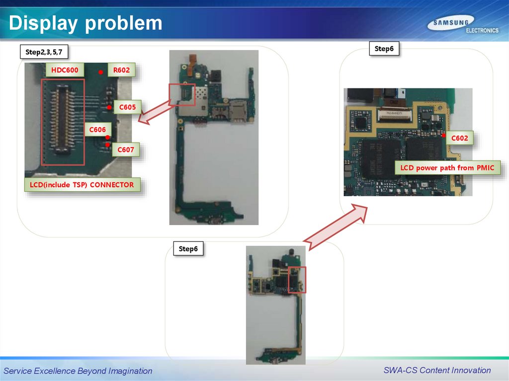
60.
Display problemStep6
Step2,3,5,7
HDC600
R602
C605
C606
C602
C607
LCD power path from PMIC
LCD(include TSP) CONNECTOR
Step6
Service Excellence Beyond Imagination
SWA-CS Content Innovation
61.
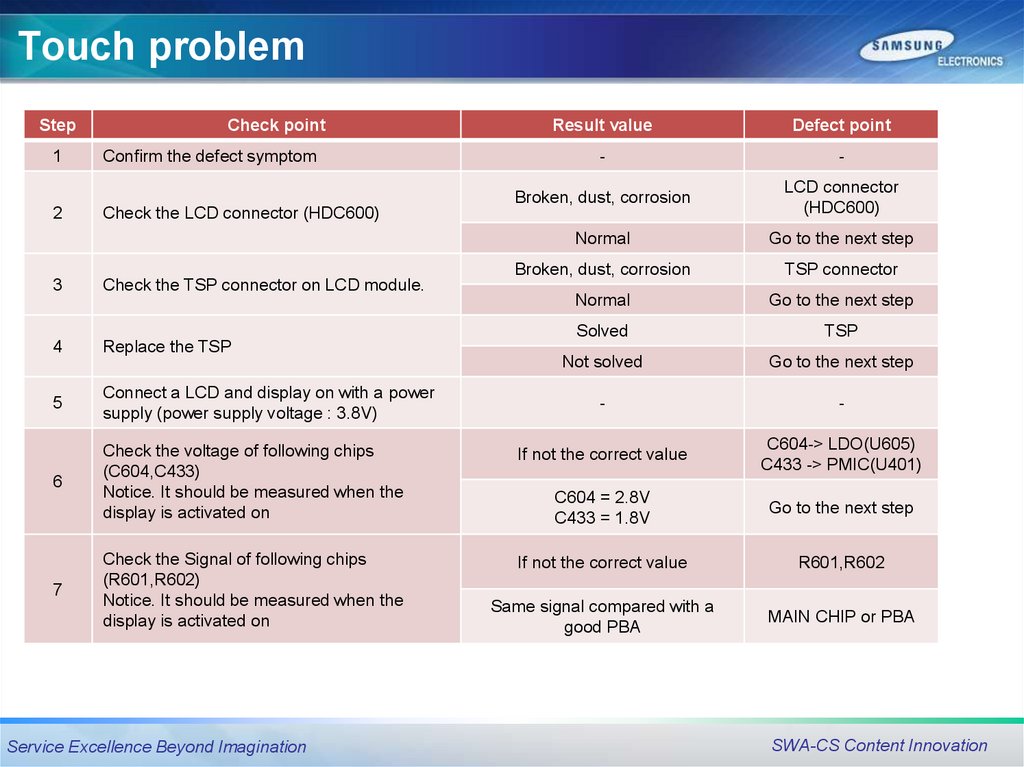
Touch problemStep
1
2
Check point
Confirm the defect symptom
Check the LCD connector (HDC600)
Result value
Defect point
-
-
Broken, dust, corrosion
LCD connector
(HDC600)
Normal
Go to the next step
Broken, dust, corrosion
TSP connector
Normal
Go to the next step
Solved
TSP
Not solved
Go to the next step
-
-
3
Check the TSP connector on LCD module.
4
Replace the TSP
5
Connect a LCD and display on with a power
supply (power supply voltage : 3.8V)
If not the correct value
C604-> LDO(U605)
C433 -> PMIC(U401)
6
Check the voltage of following chips
(C604,C433)
Notice. It should be measured when the
display is activated on
C604 = 2.8V
C433 = 1.8V
Go to the next step
Check the Signal of following chips
(R601,R602)
Notice. It should be measured when the
display is activated on
If not the correct value
R601,R602
Same signal compared with a
good PBA
MAIN CHIP or PBA
7
Service Excellence Beyond Imagination
SWA-CS Content Innovation
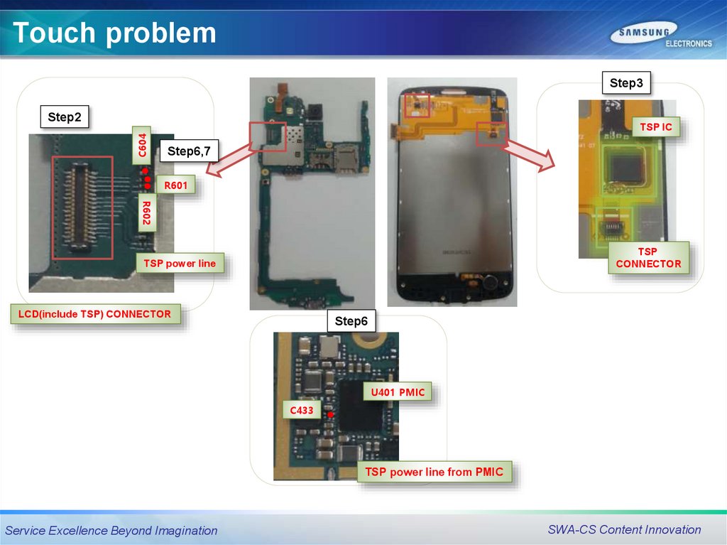
62.
Touch problemStep3
Step2
C604
TSP IC
Step6,7
R601
R602
TSP
CONNECTOR
TSP power line
LCD(include TSP) CONNECTOR
Step6
U401 PMIC
C433
TSP power line from PMIC
Service Excellence Beyond Imagination
SWA-CS Content Innovation
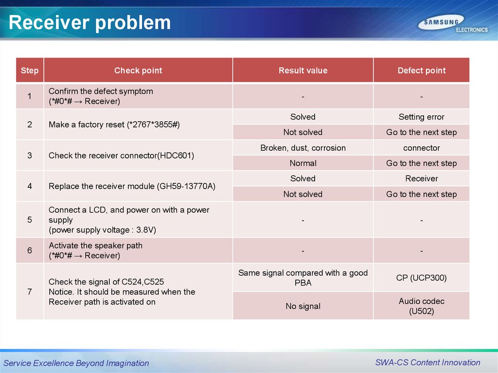
63.
Receiver problemStep
Check point
Result value
Defect point
-
-
Solved
Setting error
Not solved
Go to the next step
Broken, dust, corrosion
connector
Normal
Go to the next step
Solved
Receiver
Not solved
Go to the next step
5
Connect a LCD, and power on with a power
supply
(power supply voltage : 3.8V)
-
-
6
Activate the speaker path
(*#0*# → Receiver)
-
-
Same signal compared with a good
PBA
CP (UCP300)
7
Check the signal of C524,C525
Notice. It should be measured when the
Receiver path is activated on
No signal
Audio codec
(U502)
1
Confirm the defect symptom
(*#0*# → Receiver)
2
Make a factory reset (*2767*3855#)
3
4
Check the receiver connector(HDC601)
Replace the receiver module (GH59-13770A)
Service Excellence Beyond Imagination
SWA-CS Content Innovation
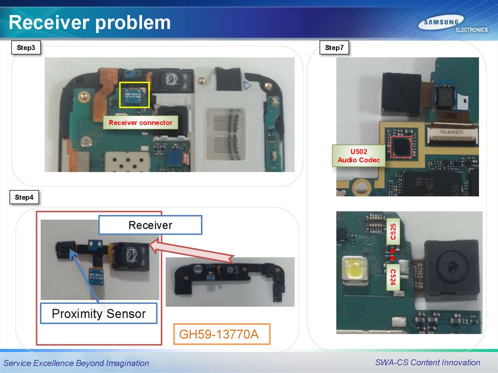
64.
Receiver problemStep3
Step7
Receiver connector
U502
Audio Codec
Step4
C525
Receiver
C524
Proximity Sensor
GH59-13770A
Service Excellence Beyond Imagination
SWA-CS Content Innovation
65.
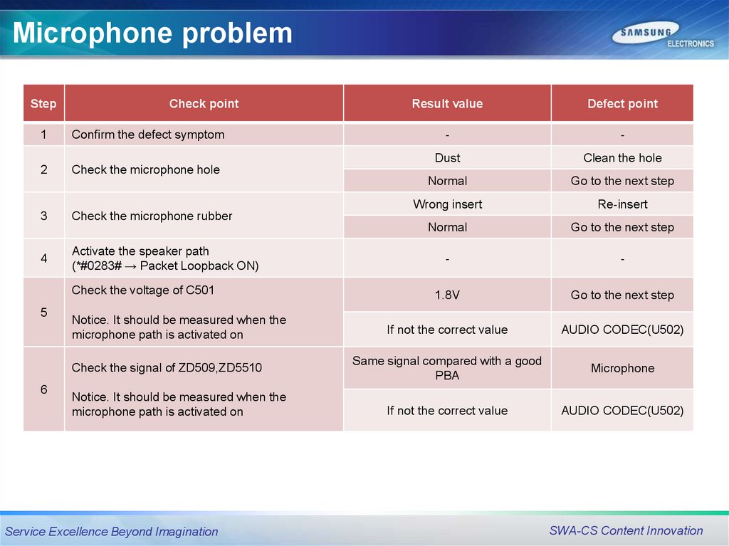
Microphone problemStep
Check point
1
Confirm the defect symptom
2
Check the microphone hole
3
4
Activate the speaker path
(*#0283# → Packet Loopback ON)
Notice. It should be measured when the
microphone path is activated on
Check the signal of ZD509,ZD5510
6
Defect point
-
-
Dust
Clean the hole
Normal
Go to the next step
Wrong insert
Re-insert
Normal
Go to the next step
-
-
1.8V
Go to the next step
If not the correct value
AUDIO CODEC(U502)
Same signal compared with a good
PBA
Microphone
If not the correct value
AUDIO CODEC(U502)
Check the microphone rubber
Check the voltage of C501
5
Result value
Notice. It should be measured when the
microphone path is activated on
Service Excellence Beyond Imagination
SWA-CS Content Innovation
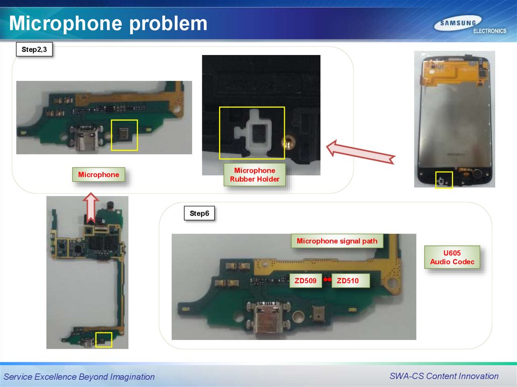
66.
Microphone problemStep2,3
Microphone
Rubber Holder
Microphone
Step6
Microphone signal path
U605
Audio Codec
ZD509
Service Excellence Beyond Imagination
ZD510
SWA-CS Content Innovation
67.
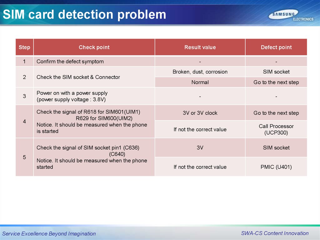
SIM card detection problemStep
Check point
1
Confirm the defect symptom
2
Check the SIM socket & Connector
3
Power on with a power supply
(power supply voltage : 3.8V)
4
Check the signal of R618 for SIM601(UIM1)
R629 for SIM600(UIM2)
Notice. It should be measured when the phone
is started
5
Check the signal of SIM socket pin1 (C636)
(C640)
Notice. It should be measured when the phone
started
Service Excellence Beyond Imagination
Result value
Defect point
-
-
Broken, dust, corrosion
SIM socket
Normal
Go to the next step
-
-
3V or 3V clock
Go to the next step
If not the correct value
Call Processor
(UCP300)
3V
SIM socket
If not the correct value
PMIC (U401)
SWA-CS Content Innovation
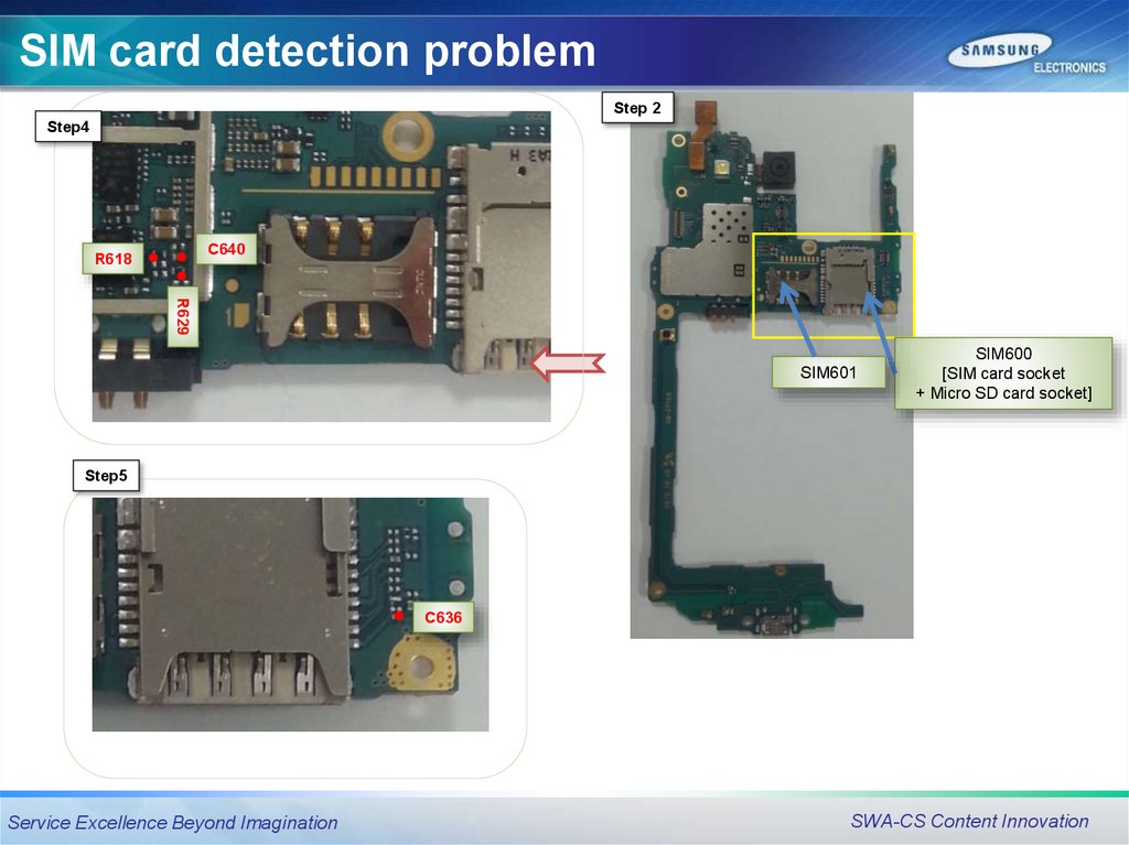
68.
SIM card detection problemStep 2
Step4
C640
R618
R629
SIM601
SIM600
[SIM card socket
+ Micro SD card socket]
Step5
C636
Service Excellence Beyond Imagination
SWA-CS Content Innovation
69.
Q&AQuestion
Service Excellence Beyond Imagination
SWA-CS Content Innovation