Похожие презентации:
Installation of self-regulating and power limiting cables
1. INSTALLATION OF SELF-REGULATING and POWER LIMITING CABLES
Private and Confidential2. Why do we install heat tracing?
Private and Confidentialpage 2
3. Purpose
This presentation is a supplement tothe Installation and Maintenance
Manual for Self-Regulating and
Power Limiting Heating Cable
Systems.
It outlines Pentair Thermal Controls
cable installation protocol.
Private and Confidential
page 3
4. Outline
Types of CablesInstallation Preparation
EHT Components
Attaching Cables
Typical SR and VPL Installation
Installing the C25-100 Connection Kit
Installation Details
Private and Confidential
page 4
5. Types of Cables
Private and Confidential6. Types of Cables
BTVQTVR
XTV
KTV
SELF REGULATING CABLES
Private and Confidential
VPL
POWER
LIMITING
page 6
7. Self-Regulating Cables
Power varies with temperature. Aspipe temperature increases the
power output decreases.
At high temperatures, the polymer
expands, reducing the number of
the conductive paths, and thus
reducing current flow.
At low temperatures, there are
many conductive paths, allowing
current to flow between the
conductors.
Private and Confidential
page 7
8. Power-Limiting Cables
The most important thing to be aware of onthe VPL cable is the location of the node. It
regulates where the cable is to be cut.
Fluoropolymer
outer jacket
Metal Braid
Power-limiting heating element
Fluoropolymer inner jacket
Fluoropolymer conductor insulation
Nickel-plated, copper
conductors (3.3 mm²)
Node connection (zone length 0.5-1.2 m)
Fluoropolymer clear jacket
Private and Confidential
page 8
9. Power-Limiting Cables
When power limitingcable is cut between
nodes.
A portion of that cable
no longer heats up.
This is why it is
important to always
leave an extra loop at
terminations for power
limiting cable.
Private and Confidential
page 9
10. Installation Preparation
Private and Confidential11. Pre-Installation Checks
Check installation documentationCheck materials
Check piping and/or equipment to be traced
Private and Confidential
page 11
12. Check Installation Documentation
Upon receiving the constructiondocumentation, or Electrical Heat
Trace (EHT) work pack, the
installer is to inspect the
documents to confirm all
documents are included and the
correct.
Private and Confidential
page 12
13. Check Installation Documentation
Size of Electrical Heat Trace(EHT) work pack changes form
job to job, but the installer
receives at a minimum the
isometric drawing(s) of the circuit.
QUANTITY SHEET
WORK CARD
Private and Confidential
HEAT TRACE ISOMETRIC(S)
INSTALLATION
CHECKLIST
MATERIALS
LIST
page 13
14. Check Installation Documentation
Confirm all isometric continuations are includedin the work pack.
Private and Confidential
page 14
15. Check Installation Documentation
Ensure that all requiredpermits are in place for the
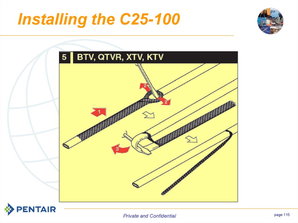
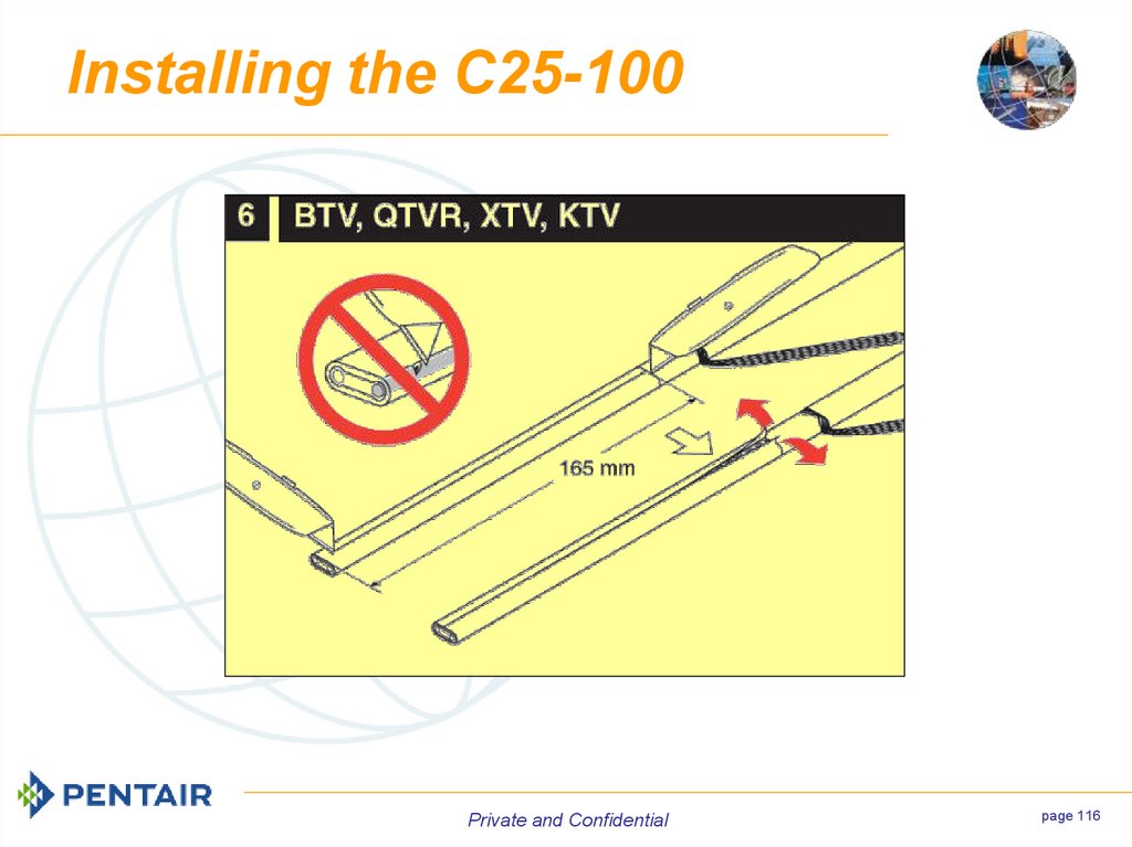
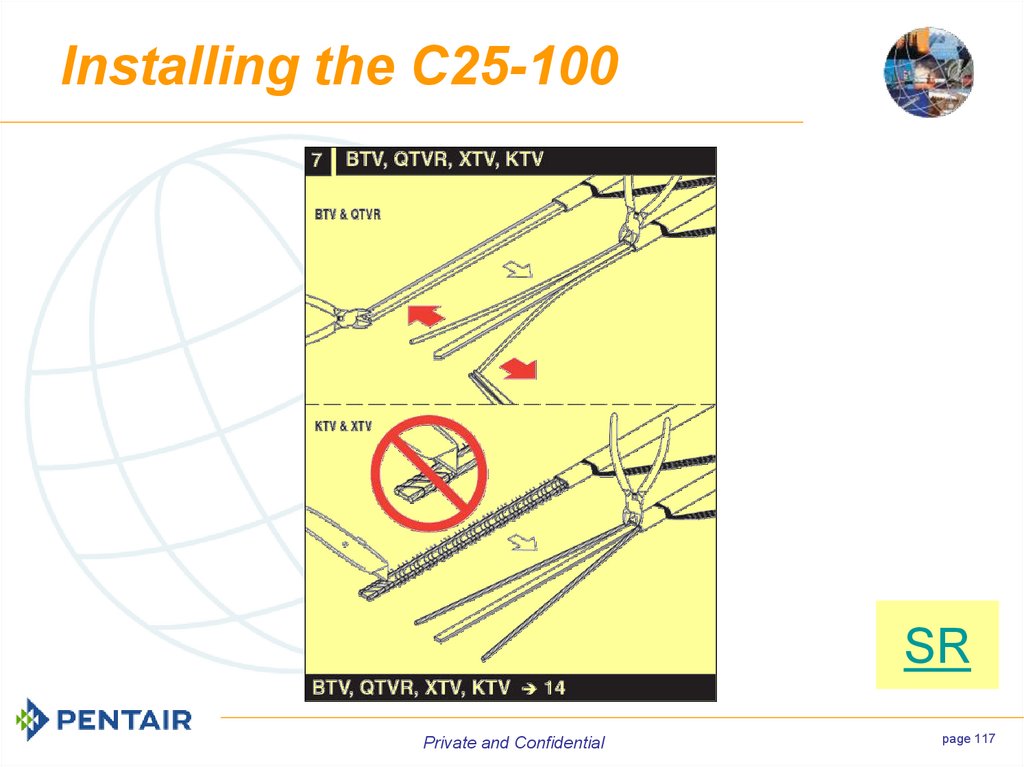
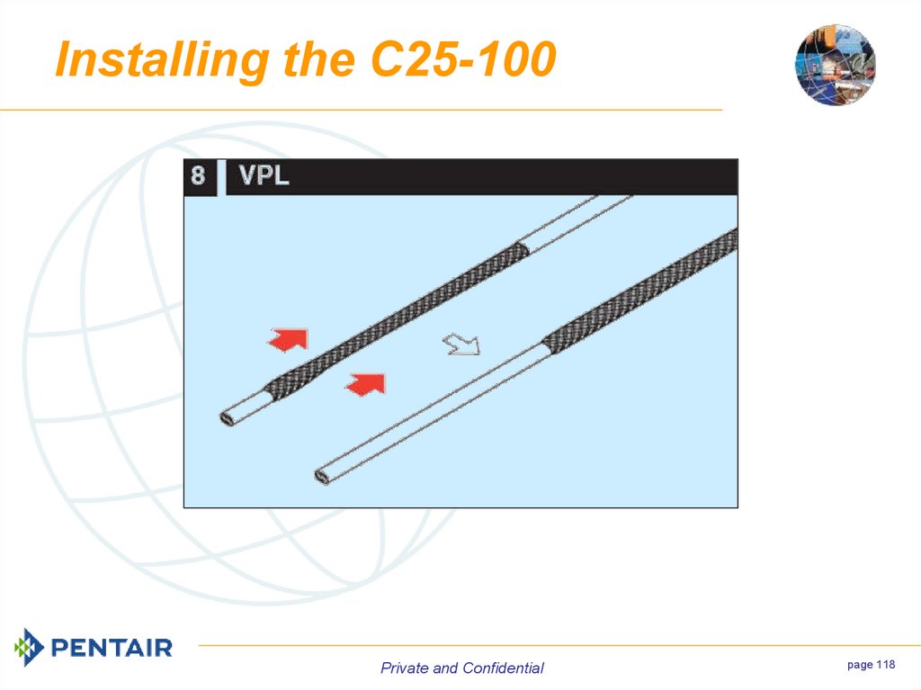
area in which the installation is
to take place.
Private and Confidential
page 15
16. Check Materials
Inspect the heating cable and components toensure that there is no visual damage.
Private and Confidential
page 16
17. Check Materials
Test the insulation resistance of the cable.Private and Confidential
page 17
18. Check Piping and/or Equipment
Ensure that the length, diameter, and the configuration ofthe piping is the same as the design documents.
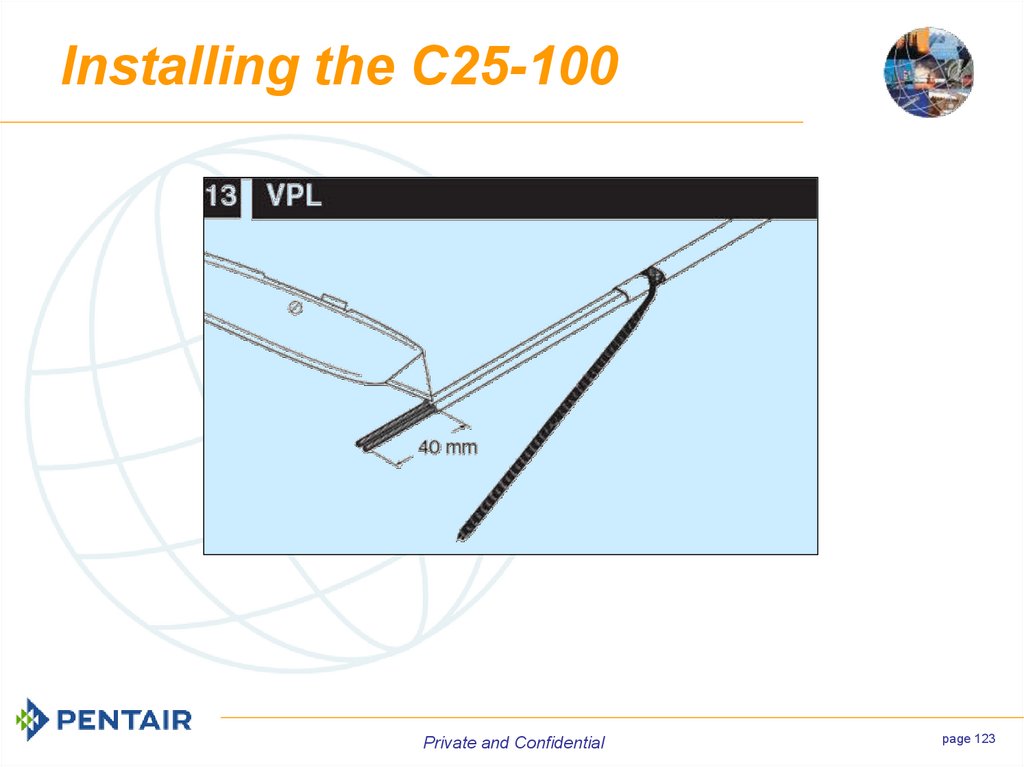
Private and Confidential
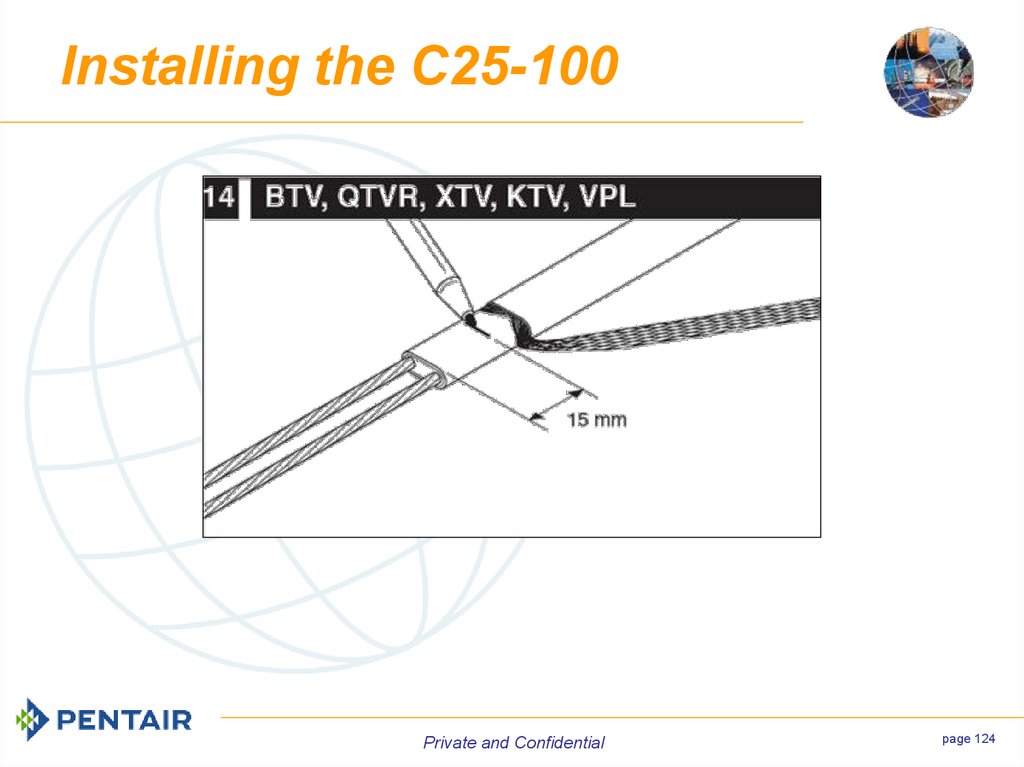
page 18
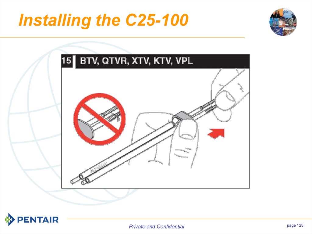
19. Check Piping and/or Equipment
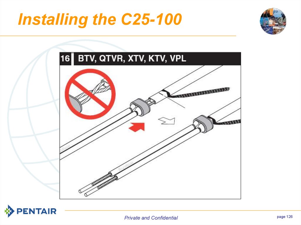
Ensure that thereis no piping or
equipment
missing.
Private and Confidential
page 19
20. Check Piping and/or Equipment
Walk the entire line and planthe routing of the heating
cable(s) on the pipe and the
heat sinks (valves, supports,
drains, etc.).
Private and Confidential
page 20
21. Pulling and Laying Out of Cable
When pulling the SR or VPLcable avoid:
Sharp edges
Excessive pulling force
Kinking or crushing
Walking on it or running over it
with equipment
Private and Confidential
page 21
22. EHT Components
Private and Confidential23. Typical Integrated EHT System
Private and Confidentialpage 23
24. Typical Modular EHT System
Private and Confidentialpage 24
25. Integrated Power Connections
Private and Confidentialpage 25
26. Integrated Power Connections
JBS-100-E(P)JBM-100-E(P)
C-150-E
(Under Insulation)
VPL
Private and Confidential
page 26
27. Modular Power Connections
Private and Confidentialpage 27
28. Modular Power Connections
JBU-100-E(P)JB-EX-25
JB-EX-27
JB-EX-28
JB-82
Private and Confidential
page 28
29. Modular Power Connections
Private and Confidentialpage 29
30. Modular Power Connections
ApplicationsInstruments and analyzers
Vessels, pumps, and other
equipment
Off pipe installation required
Wall mounts
Customer preference
Replacement of existing EHT
systems
Private and Confidential
page 30
31. Connection Kit
The C25-100 is the most commonly used connection kitfor both self-regulating and power limiting cables.
Private and Confidential
page 31
32. Insulation Entry Kit
Private and Confidentialpage 32
33. Tee Connections
Private and Confidentialpage 33
34. Tee Connections
T-100JBM-100-E(P)
S-150
(Under Insulation)
VPL
Private and Confidential
page 34
35. End Seals
Private and Confidentialpage 35
36. End Seals
The E-100-E and theE-100-L-E are both
high profile (above the
insulation) end seals.
The E-06 (for BTV &
QTVR), E-19 (for XTV
& KTV) , and the E-50
(for VPL) are low
profile heat applied
end seals.
The E-150 is a low
profile cold applied
end seals.
VPL
Private and Confidential
page 36
37. Splice Kits
Private and Confidentialpage 37
38. Splice Kits
The T-100 is high profile(above the insulation) splice
kit that can handle up to 3
cables.
The S-19 (for BTV), S-21 (for
QTV), and the S-69 (KTV
and XTV) are heat applied
low profile splices.
VPL
The S-150 is a cold applied
low profile splice.
VPL
Private and Confidential
page 38
39. Temperature Sensors
Private and Confidentialpage 39
40. Temperature Sensors
AMBIENT CONTROLMONI-PT100-EXEAMB
T-M-10-S/0+50C
AT-TS-13
RAYSTAT-EX-04
RAYSTAT-ECO-10
FOR HAZARDOUS AREAS
Private and Confidential
page 40
41. Temperature Sensors
LINE SENSINGT-M-X-S/…C
AT-TS-14
MONI-PT100EXE
RAYSTAT-EX-03
RAYSTATEX-02
RAYSTATCONTROL-10
FOR HAZARDOUS AREAS
Private and Confidential
page 41
42. Temperature Sensors
DUAL SENSING(control and limiter)
T-M-X-S/+X+YC/EX
Private and Confidential
page 42
43. Fixing SR and VPL Cables
Private and Confidential44. Fixing Cables
Cables are typically fixed atan interval of 300mm and
additionally where
necessary (i.e.. Valves,
pumps, drains, electrical
devices, etc.)
Private and Confidential
page 44
45. Fixing Cables
Glass tape isEXCESSIVE TAPE
expensive and
should not be used
excessively.
Private and Confidential
page 45
46. Fixing Cables
When approved byengineering, aluminum tape
(AT-180) can be used to fix
cable and thermostat
sensors to piping and
equipment.
Private and Confidential
page 46
47. Fixing Cables
DO NOT USE:Metal Strapping,
Vinyl Electrical
Tape, or Duct
Tape
GT-66 or
GS-54
Private and Confidential
page 47
48. Fixing Cables
If possible place thecables at the 4 o’clock
and 8 o’clock positions.
For circuits with greater
than 2 passes evenly
space the cable on the
bottom half of the pipe.
Private and Confidential
page 48
49. Fixing Cables
Minimum Bending RadiusBTV & QTV
XTV
KTV
VPL
at 20°C
15mm
15mm
25mm
20mm
at -60°C
35mm
50mm
50mm
20mm
Private and Confidential
page 49
50. Bending Cables
Private and Confidentialpage 50
51. Fixing Cable
Do not installtrace so that it is
locked in place.
This trace was
wrapped around
the valve locking
it in place once
either side of the
valve is insulated.
Private and Confidential
page 51
52. Fixing Cables
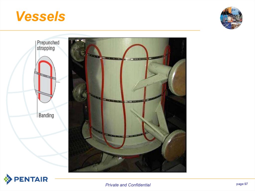
Installation on tanks typically requires additional prepunched strapping.Private and Confidential
page 52
53. Fixing Cables
Caution: The prepunched metal straphas an extremely
sharp edge on the
bottom, thus it should
be folded back onto
the cable.
Private and Confidential
page 53
54. Fixing Cables
Self regulating cables allow for multiple overlappingof the cable on itself but due to the loss in heat output
this is to be avoided .
VPL cables can only overlap themselves once.
Private and Confidential
page 54
55. Typical SR & VPL Installation
Typical SR & VPLInstallation
Private and Confidential
56. Installation
On simple/straight the cablecan be pulled from a
stationary reel holder.
The meter marks on the
cable can be used to
indicate how much has been
reeled out.
Private and Confidential
page 56
57. Installation
If absolutely certain of therequired length, the cable
could be cut from the reel.
CAUTION: This can lead to
the cable being too short
(requiring a splice or a new
cable) or being to long
(wastage).
Private and Confidential
page 57
58. Installation
WhenTape down the
piping beginning
is too
complex the reel
must be carried
alongside the
piping as it is
taped to the pipe.
Run the allowances
reel along the
Leaving
for
pipe
taping
thedevices
trace as
all the
piping
go.
andyou
supports.
Private and Confidential
page 59
59. Installation
DetailsPrivate and Confidential
60. Installation Details
Component AllowancesAlways consult the
design specifications
(or Pentair Thermal
Controls product
literature if there is no
design spec.) for the
additional heating
cable lengths for
piping components.
Private and Confidential
page 61
61. Component Allowances
ValvesPrivate and Confidential
page 62
62. Valves
This drawing showsthe general
installation method.
Configurations will
change for different
valve shapes and
sizes and heating
cable lengths.
Private and Confidential
page 63
63. Valves
Private and Confidentialpage 64
64. Valves
Private and Confidentialpage 65
65. Valves
Private and Confidentialpage 66
66. Valves
Private and Confidentialpage 67
67. Valves
Private and Confidentialpage 68
68. Valves
If it is physicallyimpossible to apply
the full recommended
cable allowance to the
body install the
excess on either side.
WELD
WELD
Private and Confidential
page 69
69. Valves
Private and Confidentialpage 70
70. Valves
If it is physicallyimpossible to apply
the full recommended
cable allowance to the
body install the
excess on either side.
WELD
WELD
Private and Confidential
page 71
71. Valves
For thin (butterfly)valves install the
excess allowance on
either side of the
valve body.
Private and Confidential
page 72
72. Valves
ElbowsPrivate and Confidential
page 73
73. Elbows
Do not install EHT on an elbow’s heel (outside radius). This areais especially vulnerable because insulators often drill pilot holes
for the screws that fasten the elbow cutouts together.
Private and Confidential
page 74
74. Elbows
Private and Confidentialpage 75
75. Elbows
FlangesPrivate and Confidential
page 76
76. Flanges
Private and Confidentialpage 77
77. Flanges
ClampsSometimes clamps are used in place of flanges. Be
sure to install enough trace so that the clamp can be
removed without having to remove cable up and/or
downstream of the clamp.
Private and Confidential
page 78
78. Clamps
Do not install cablesunderneath anything
which clamps around
the pipe.
Private and Confidential
page 79
79. Clamps
Pipe HangersPrivate and Confidential
page 80
80. Pipe Hangers
Do not clamp heating cablewith support. Cable must be
over the support
An allowance is not
required for hangers, only
enough extra so that the
hangers clamp may be
removed without having to
remove a lot of cable up
and/or downstream of the
hanger.
Private and Confidential
page 81
81. Pipe Hangers
Pipe ShoesPrivate and Confidential
page 82
82. Pipe Shoes
The typical pipe shoeallowance is 1.2m but
always confirm with the
drawing or specifications
as to what is required.
The allowance loops
should always exceed the
length of the shoe so that
it can be easily fixed on
either side of the shoe.
Private and Confidential
page 83
83. Pipe Shoes
Linear LengthAllowance (typically 1.2m)
Private and Confidential
page 84
84. Pipe Shoes
Dummy SupportsPrivate and Confidential
page 85
85. Dummy Supports
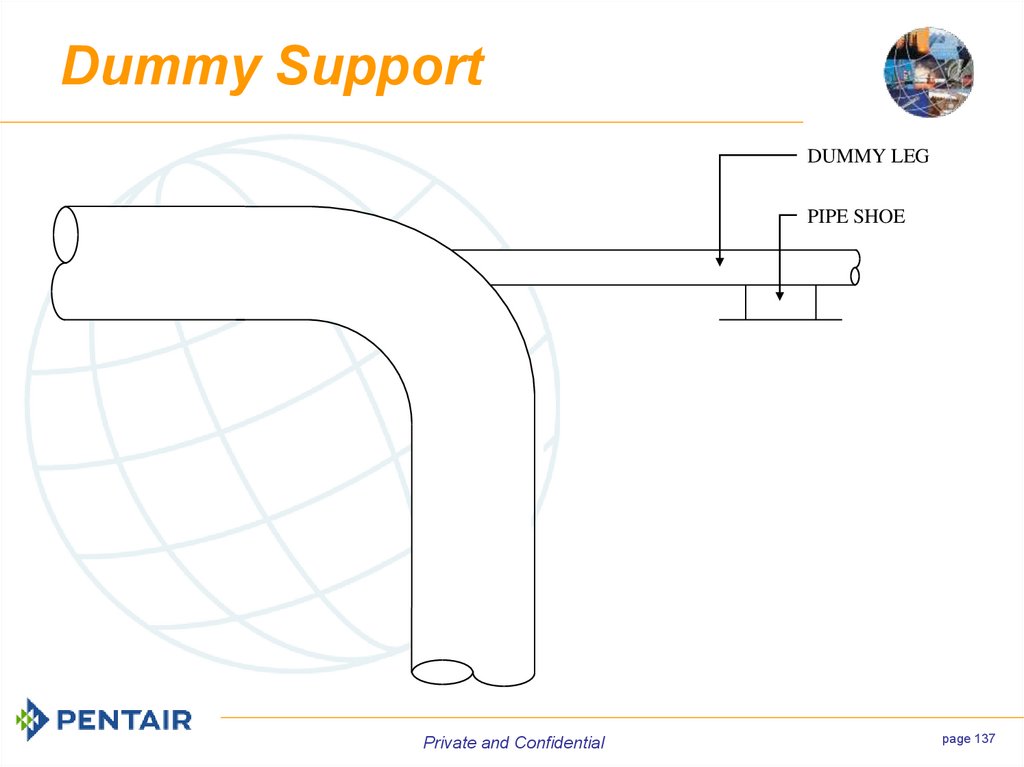
Dummy supports (or dummylegs) are large heat sinks
which typically require 1.2m
of extra cable per pass.
Private and Confidential
page 86
86. Dummy Supports
DUMMY LEGPIPE SHOE
Linear Length
Adder (Typically 1.2m)
Private and Confidential
page 87
87. Dummy Supports
TrunnionsTrunnions are basically just two dummy supports thus they
need twice as much allowance.
Private and Confidential
page 88
88. Dummy Supports
Dead LegsDead legs are very rare but they are easily mistaken for a
dummy leg. Dead legs have “T” fittings with a short piece of
blocked off piping, where a dummy leg is just a support at an
elbow.
A dead leg fills with stagnant fluid thus it must be traced, the
dummy leg allowance will not do.
DEAD LEG
(MI cable shown)
Private and Confidential
DUMMY LEG
page 89
89. Dummy Supports
PumpsPrivate and Confidential
page 90
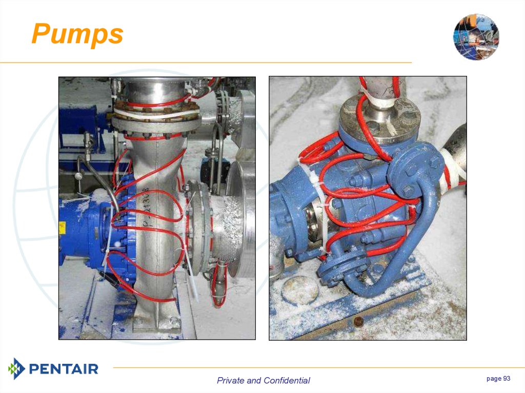
90. Pumps
Pumps vary in size, type, and shapewith various methods of being
mounted. This makes it difficult to
show a standard installation since
almost every pump configuration is
unique.
Plan the installation and have it
approved by the site supervisor or the
client.
Pumps often appear in pairs so be
sure to install the parallel pumps in the
same style.
Private and Confidential
page 91
91. Pumps
Private and Confidentialpage 92
92. Pumps
Private and Confidentialpage 93
93. Pumps
VesselsPrivate and Confidential
page 94
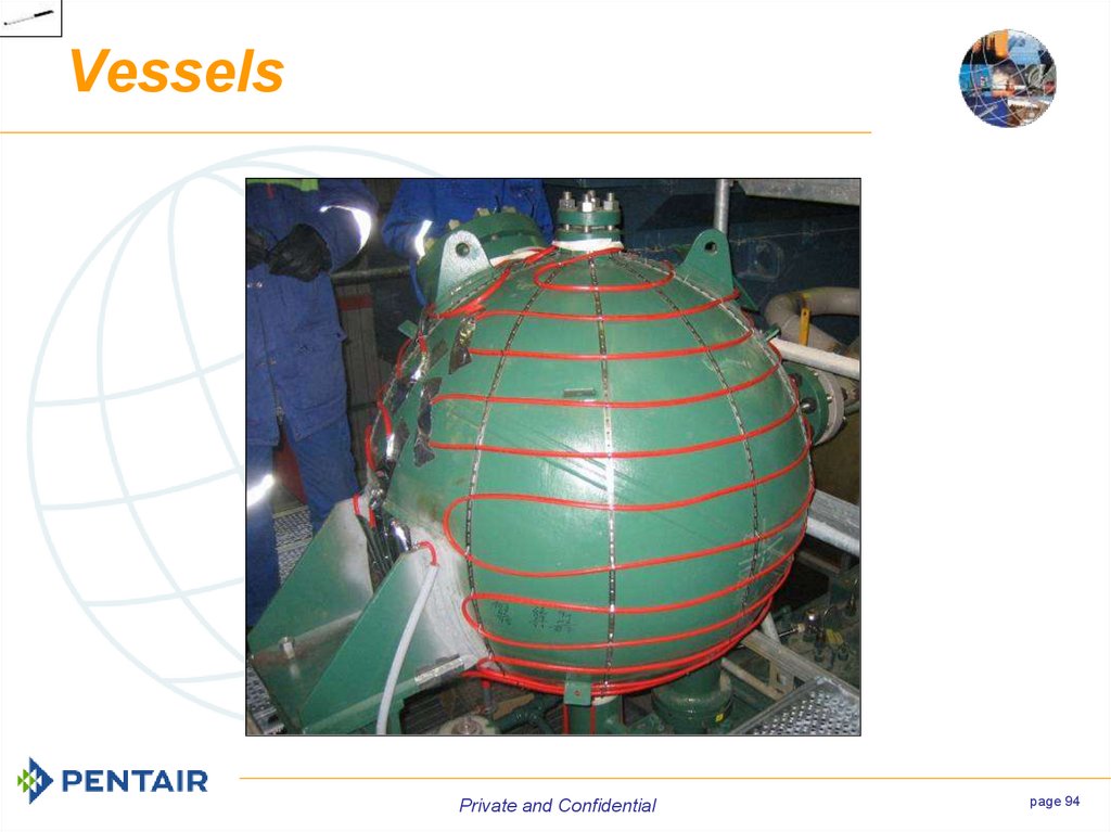
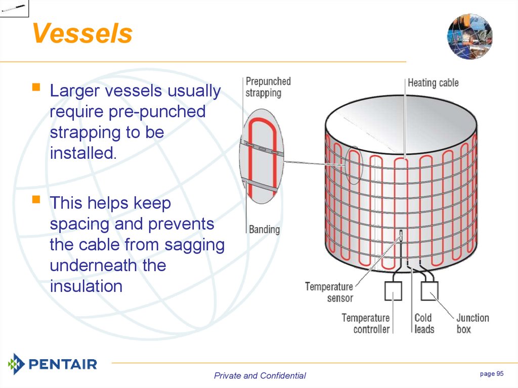
94. Vessels
Larger vessels usuallyrequire pre-punched
strapping to be
installed.
This helps keep
spacing and prevents
the cable from sagging
underneath the
insulation
Private and Confidential
page 95
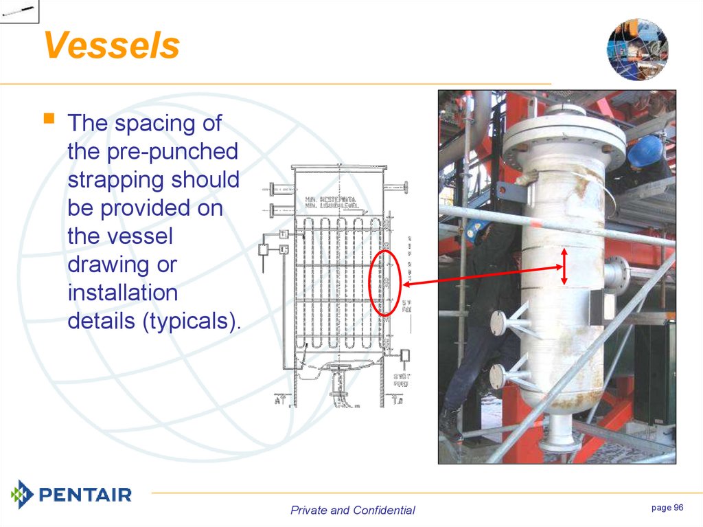
95. Vessels
The spacing ofthe pre-punched
strapping should
be provided on
the vessel
drawing or
installation
details (typicals).
Private and Confidential
page 96
96. Vessels
Private and Confidentialpage 97
97. Vessels
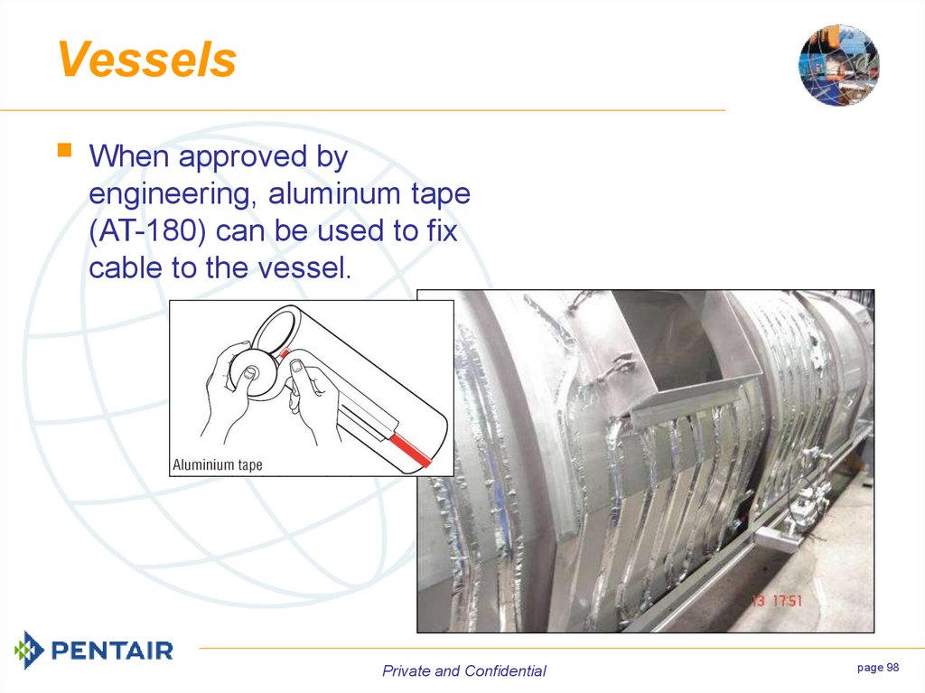
When approved byengineering, aluminum tape
(AT-180) can be used to fix
cable to the vessel.
Private and Confidential
page 98
98. Vessels
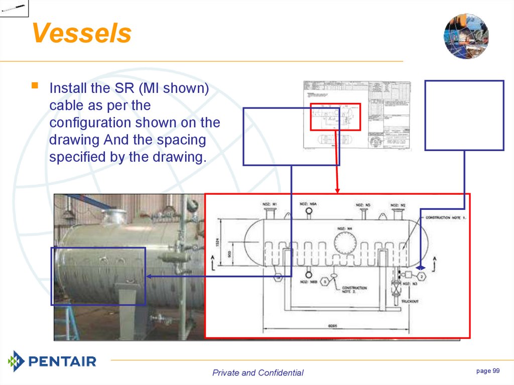
Install the SR (MI shown)cable as per the
configuration shown on the
drawing And the spacing
specified by the drawing.
Private and Confidential
page 99
99. Vessels
Vents and DrainsPrivate and Confidential
page 100
100. Vents and Drains
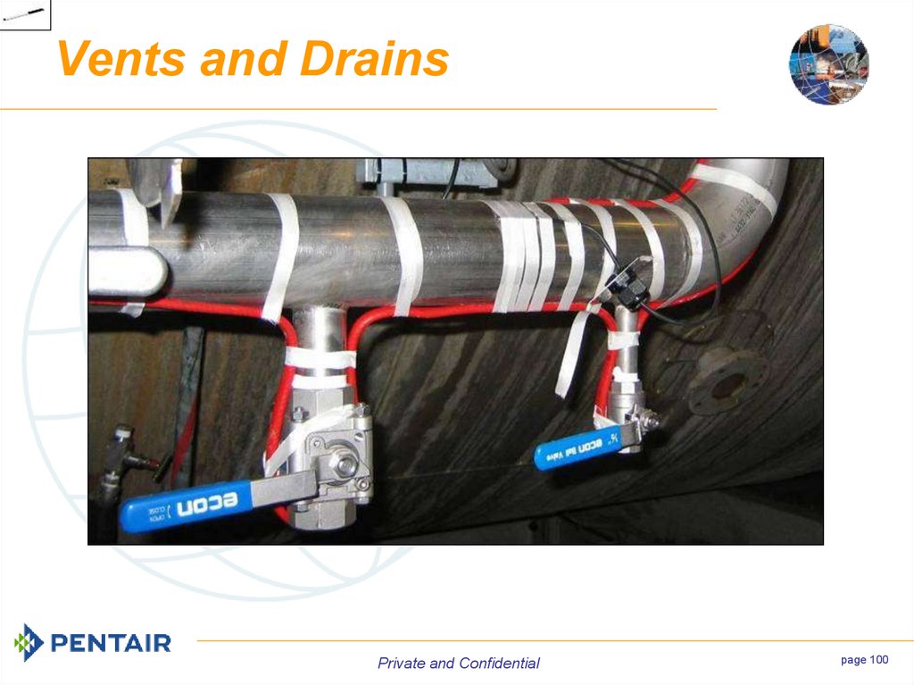
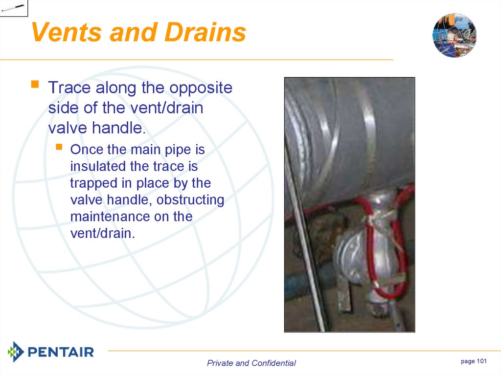
Trace along the oppositeside of the vent/drain
valve handle.
Once the main pipe is
insulated the trace is
trapped in place by the
valve handle, obstructing
maintenance on the
vent/drain.
Private and Confidential
page 101
101. Vents and Drains
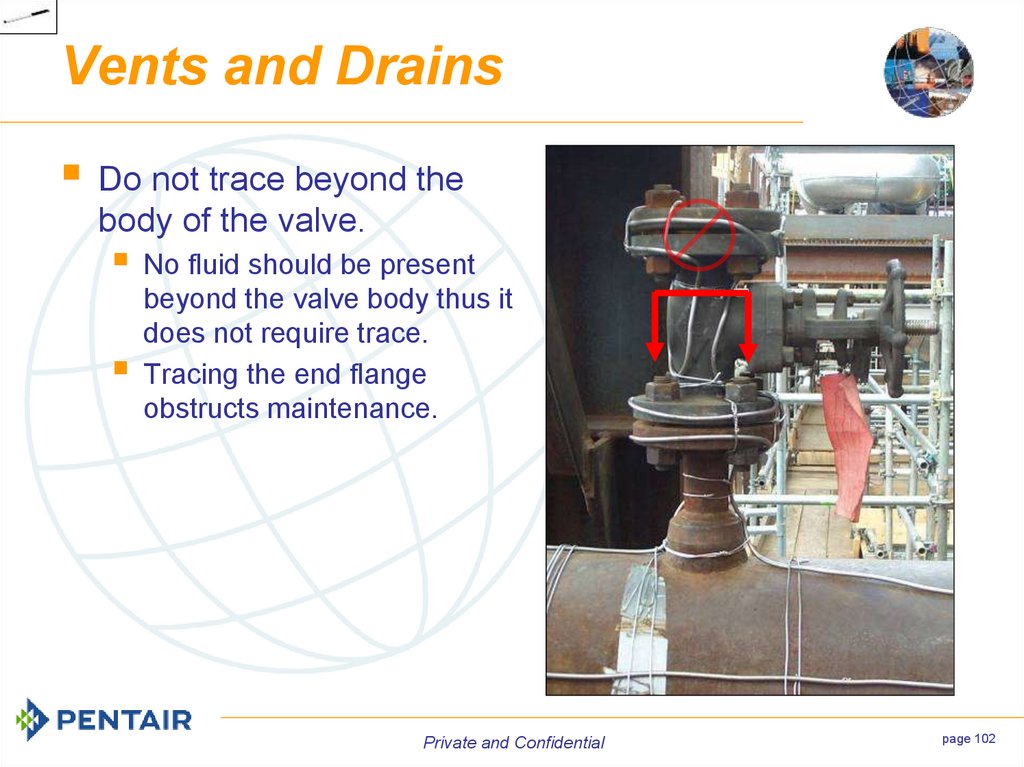
Do not trace beyond thebody of the valve.
No fluid should be present
beyond the valve body thus it
does not require trace.
Tracing the end flange
obstructs maintenance.
Private and Confidential
page 102
102. Vents and Drains
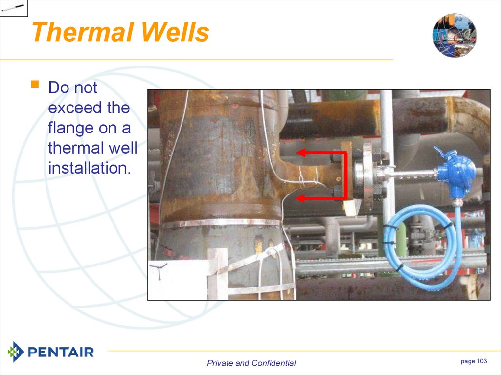
Thermal WellsDo not
exceed the
flange on a
thermal well
installation.
Private and Confidential
page 103
103. Thermal Wells
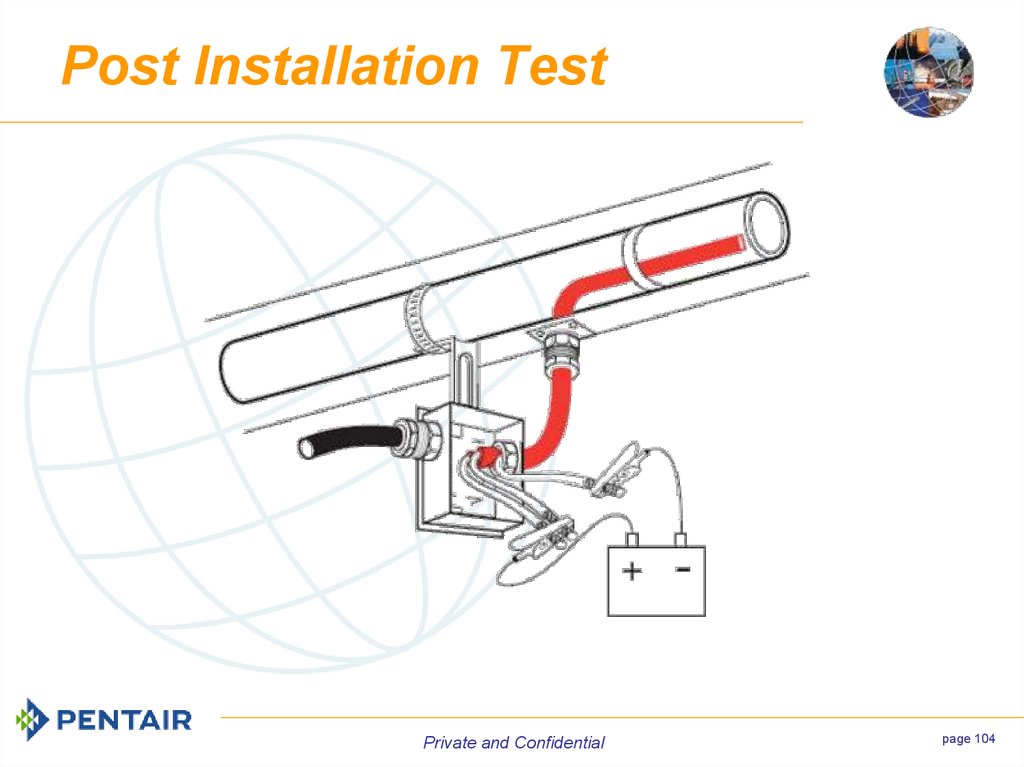
Post Installation TestPrivate and Confidential
page 104
104. Post Installation Test
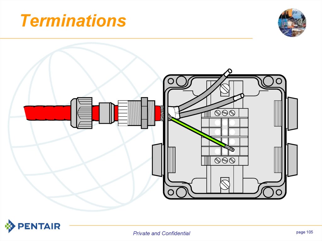
TerminationsPrivate and Confidential
page 105
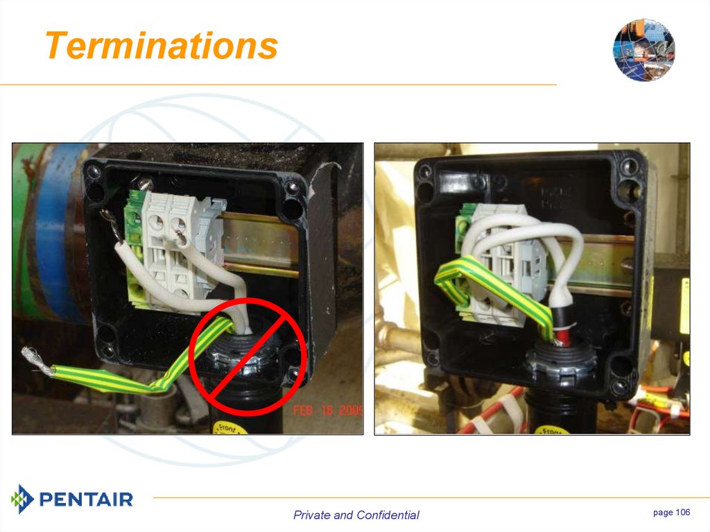
105. Terminations
Private and Confidentialpage 106
106. Terminations
Installing theC25-100
Connection Kit
Private and Confidential
107. Installing the C25-100 Connection Kit
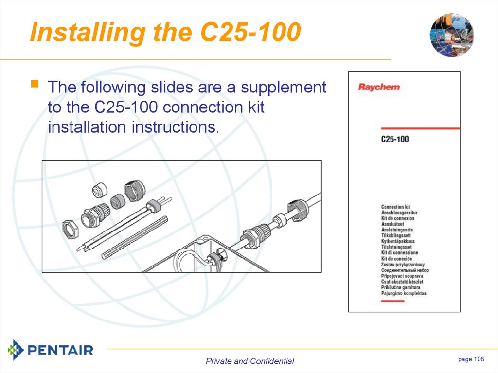
Installing the C25-100The following slides are a supplement
to the C25-100 connection kit
installation instructions.
Private and Confidential
page 108
108. Installing the C25-100
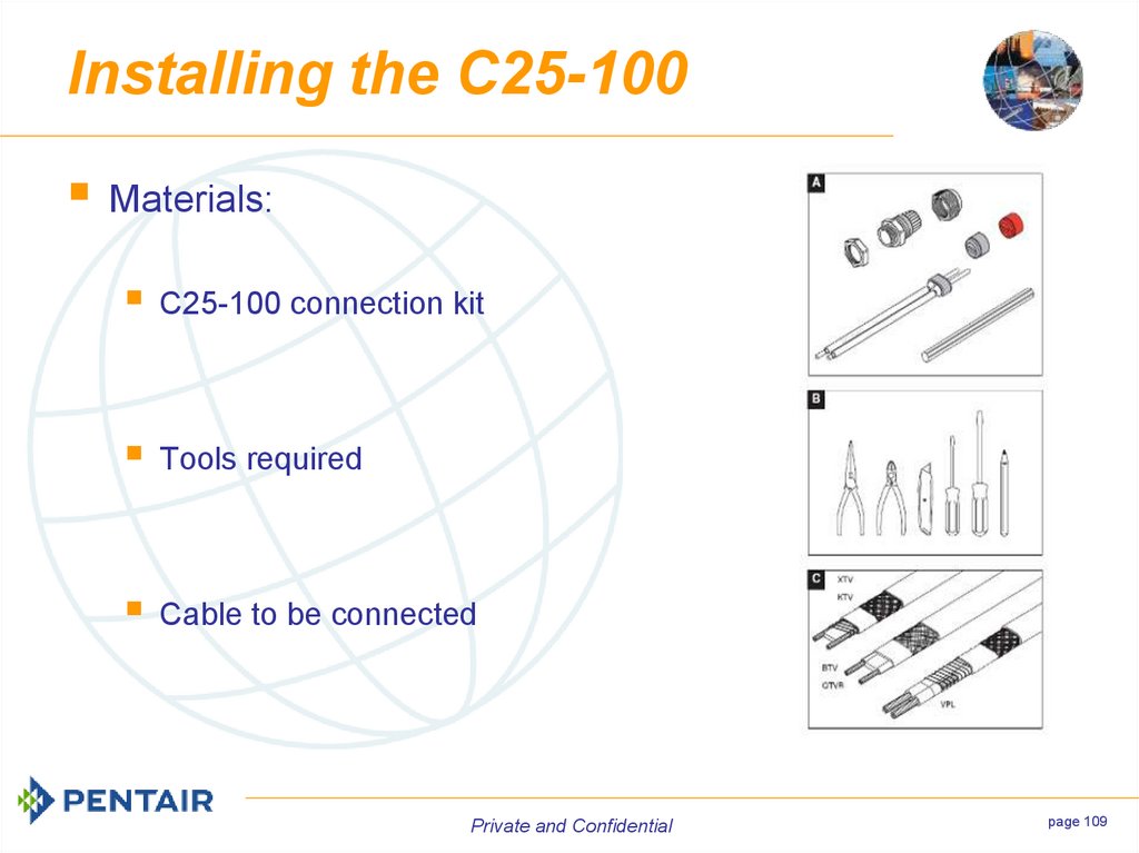
Materials:C25-100 connection kit
Tools required
Cable to be connected
Private and Confidential
page 109
109. Installing the C25-100
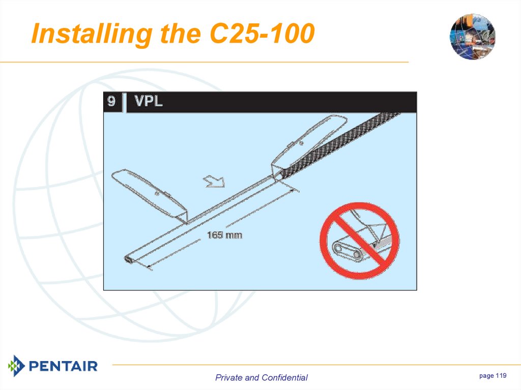
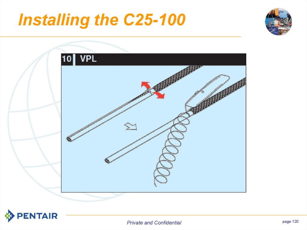
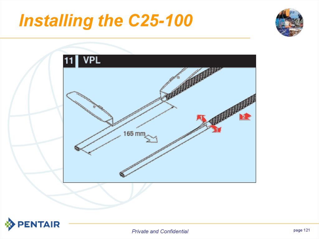
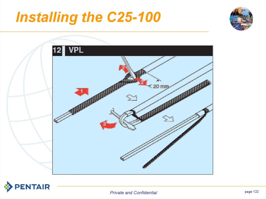
Slides with white backgroundsapply to both SR and VPL
cables.
Slides with blue backgrounds
apply only to VPL cable.
Slides with yellow backgrounds
apply only to SR cables.
Private and Confidential
page 110
110. Installing the C25-100
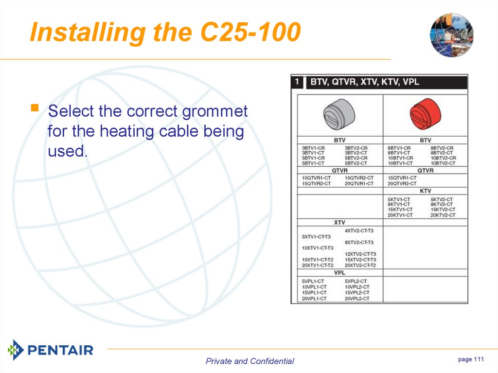
Select the correct grommetfor the heating cable being
used.
Private and Confidential
page 111
111. Installing the C25-100
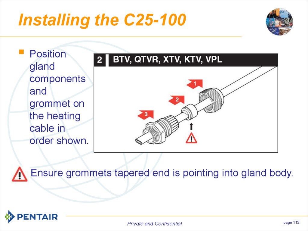
Positiongland
components
and
grommet on
the heating
cable in
order shown.
Ensure grommets tapered end is pointing into gland body.
Private and Confidential
page 112
112. Installing the C25-100
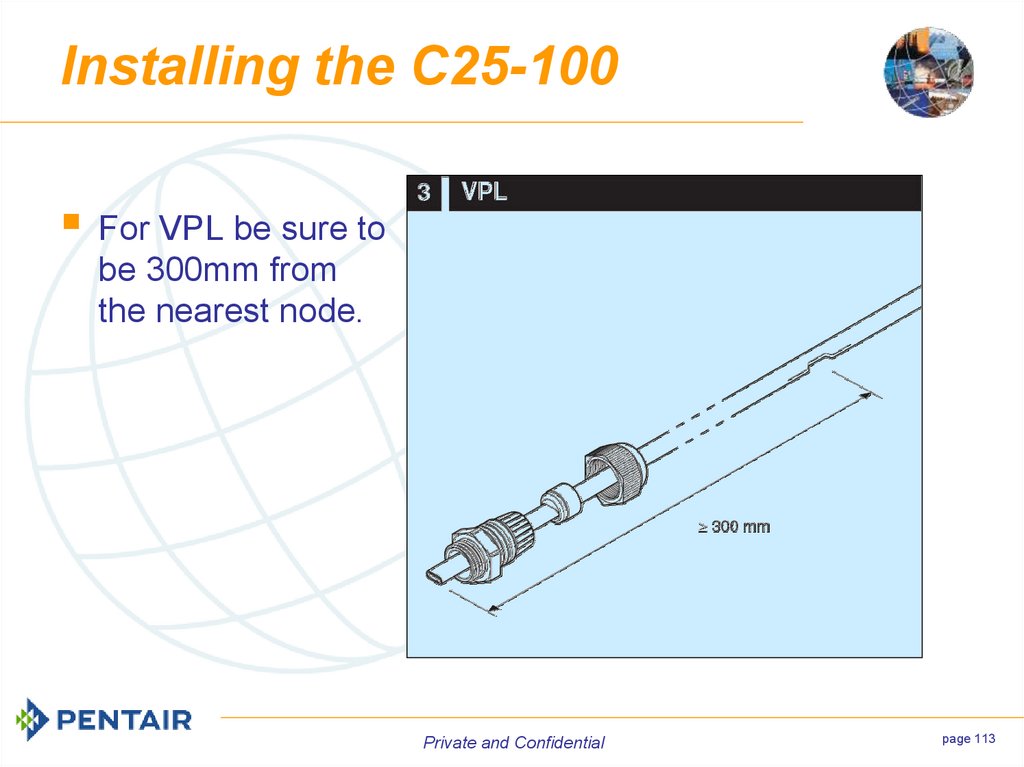
For VPL be sure tobe 300mm from
the nearest node.
Private and Confidential
page 113
113. Installing the C25-100
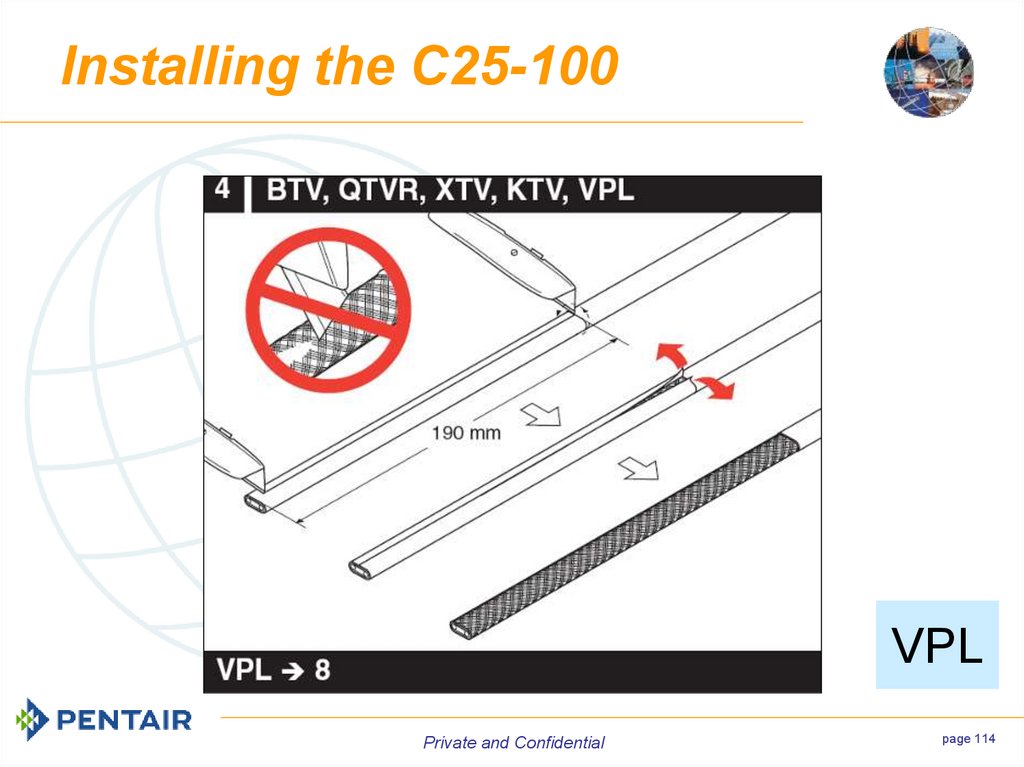
VPLPrivate and Confidential
page 114
114. Installing the C25-100
Private and Confidentialpage 115
115. Installing the C25-100
Private and Confidentialpage 116
116. Installing the C25-100
SRPrivate and Confidential
page 117
117. Installing the C25-100
Private and Confidentialpage 118
118. Installing the C25-100
Private and Confidentialpage 119
119. Installing the C25-100
Private and Confidentialpage 120
120. Installing the C25-100
Private and Confidentialpage 121
121. Installing the C25-100
Private and Confidentialpage 122
122. Installing the C25-100
Private and Confidentialpage 123
123. Installing the C25-100
Private and Confidentialpage 124
124. Installing the C25-100
Private and Confidentialpage 125
125. Installing the C25-100
Private and Confidentialpage 126
126. Installing the C25-100
Private and Confidentialpage 127
127. Installing the C25-100
Private and Confidentialpage 128
128. Installing the C25-100
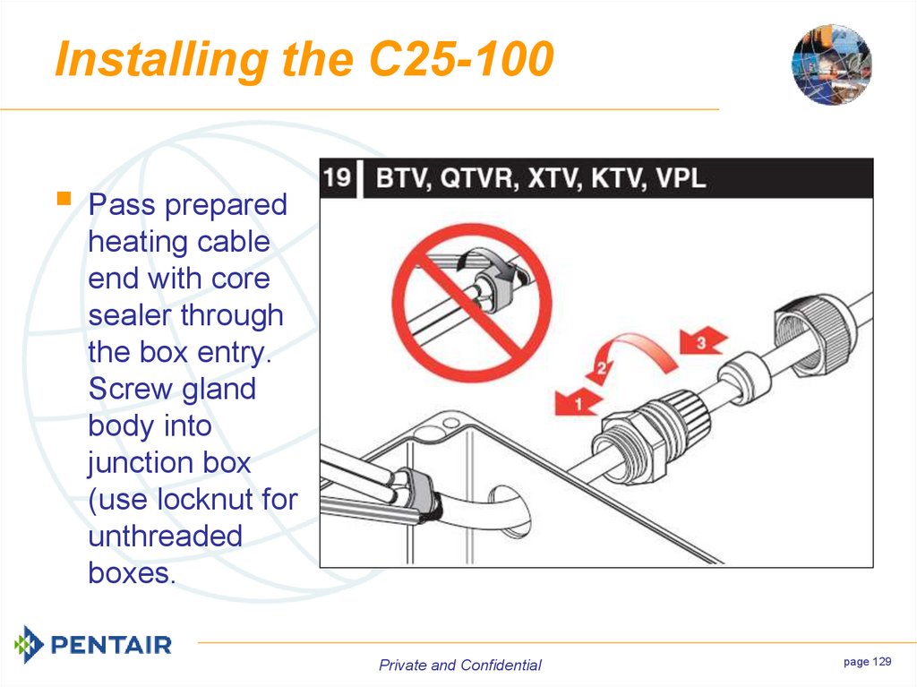
Pass preparedheating cable
end with core
sealer through
the box entry.
Screw gland
body into
junction box
(use locknut for
unthreaded
boxes.
Private and Confidential
page 129
129. Installing the C25-100
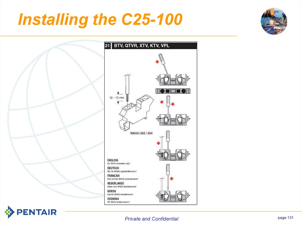
Position grommetin gland body,
ensuring it is
sealed squarely
and tighten back
nut securely.
Connect
conductors and
braid to the
appropriate
terminals.
Private and Confidential
page 130
130. Installing the C25-100
Private and Confidentialpage 131
131. Installing the C25-100
The EndThank You for Your
Attention
Private and Confidential
132. The End Thank You for Your Attention
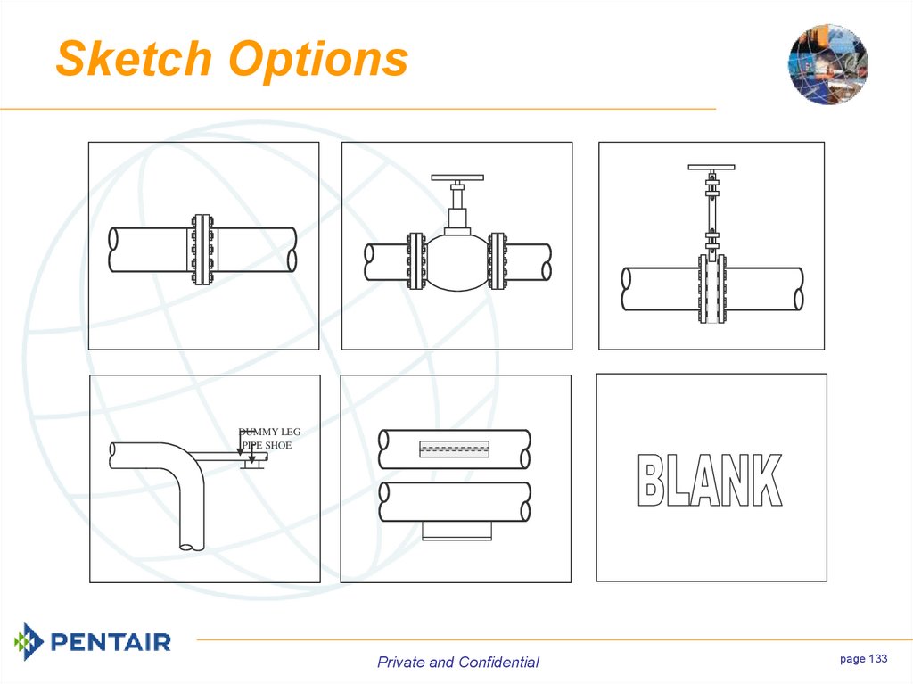
Sketch OptionsDUMMY LEG
PIPE SHOE
Private and Confidential
page 133
133. Sketch Options
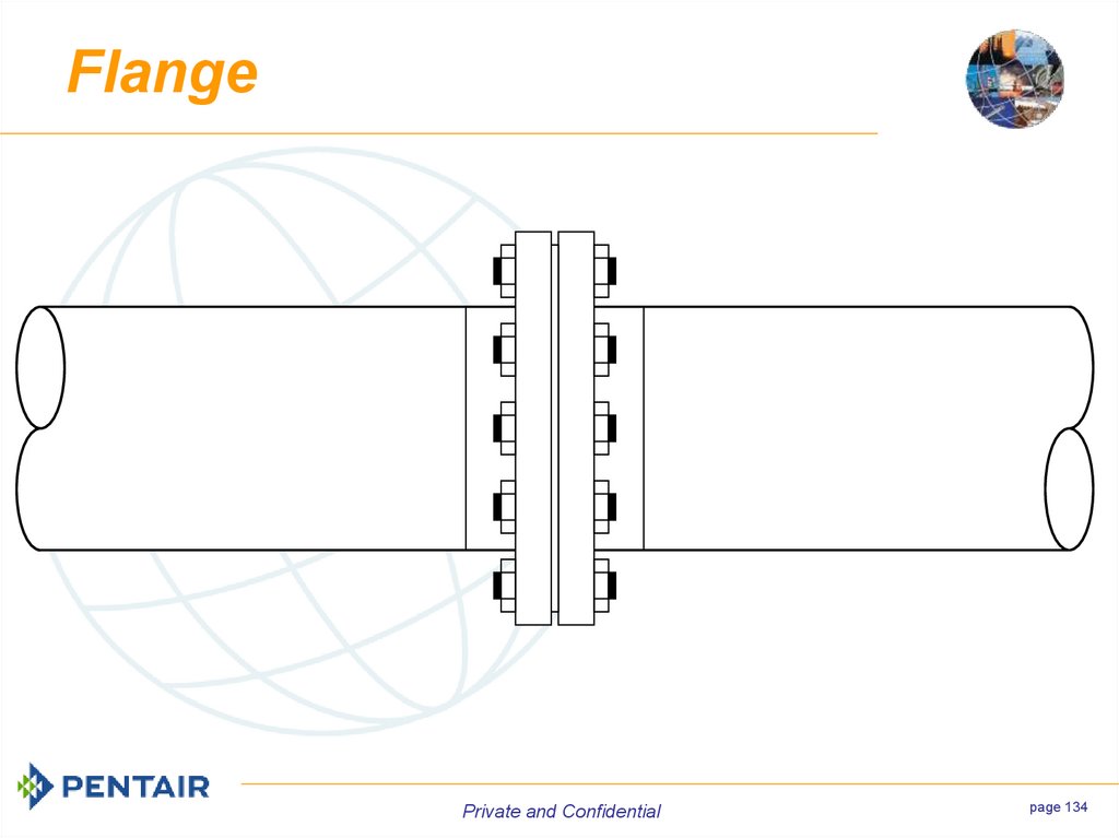
FlangePrivate and Confidential
page 134
134. Flange
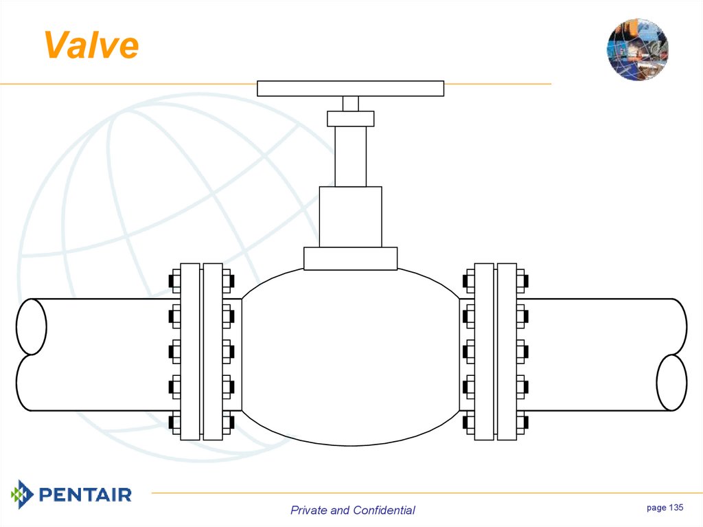
ValvePrivate and Confidential
page 135
135. Valve
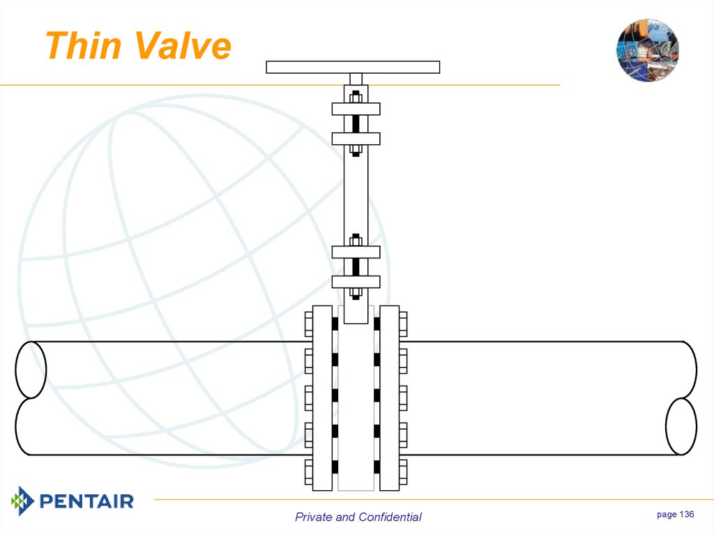
Thin ValvePrivate and Confidential
page 136
136. Thin Valve
Dummy SupportDUMMY LEG
PIPE SHOE
Private and Confidential
page 137
137. Dummy Support
Pipe ShoePrivate and Confidential
page 138
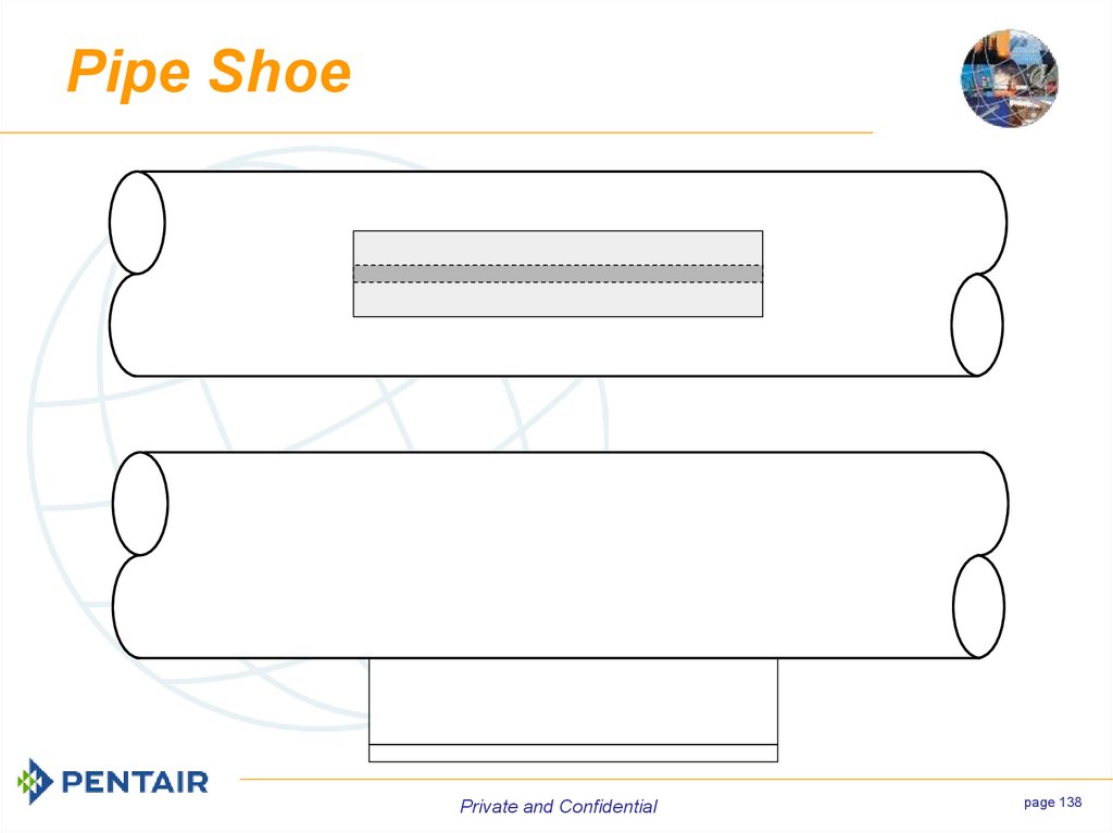
138. Pipe Shoe
BlankPrivate and Confidential
page 139







 Промышленность


