


 Механика
Похожие презентации:

")

 - Technical Highlights")


 Application Model")


Monitor panel
1.
3. Monitor panelC/S Team
2.
1. Gauge panel2. Warning lamp
3. Multi display LCD
4. Switch panel
5. Main menu
6. Special menu
C/S Team
3.
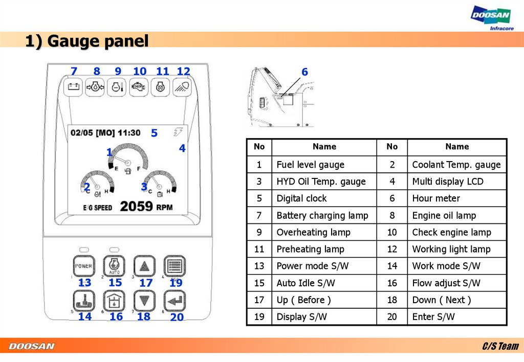
1) Gauge panel7
8
9
10 11 12
6
5
4
1
2
13
14
3
15
16
17
18
19
20
No
Name
No
Name
1
Fuel level gauge
2
Coolant Temp. gauge
3
HYD Oil Temp. gauge
4
Multi display LCD
5
Digital clock
6
Hour meter
7
Battery charging lamp
8
Engine oil lamp
9
Overheating lamp
10
Check engine lamp
11
Preheating lamp
12
Working light lamp
13
Power mode S/W
14
Work mode S/W
15
Auto Idle S/W
16
Flow adjust S/W
17
Up ( Before )
18
Down ( Next )
19
Display S/W
20
Enter S/W
C/S Team
4.
1) Gauge panel- Steering consol (Wheel)
1
8
3 4
5
6
7
2
No
Name
No
Name
No
Name
1
Combination S/W
2
Hazard lamp S/W
3
Turn signal (Left)
4
High beam light
5
Ram lock lamp
6
Turn signal (Right)
7
Working,traveling S/W
8
Travel select S/W
C/S Team
5.
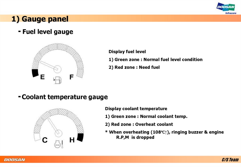
1) Gauge panel- Fuel level gauge
Display fuel level
1) Green zone : Normal fuel level condition
2) Red zone : Need fuel
- Coolant temperature gauge
Display coolant temperature
1) Green zone : Normal coolant temp.
2) Red zone : Overheat coolant
* When overheating (108℃↑), ringing buzzer & engine
R.P,M is dropped
C/S Team
6.
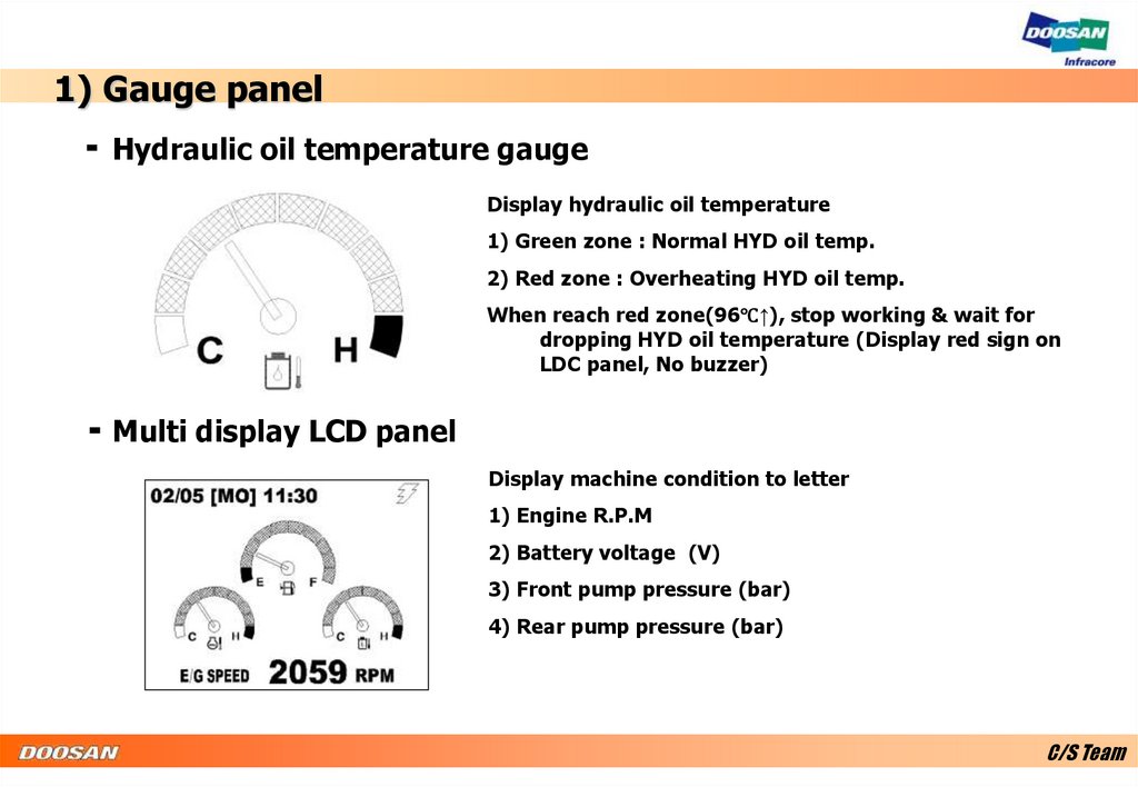
1) Gauge panel- Hydraulic oil temperature gauge
Display hydraulic oil temperature
1) Green zone : Normal HYD oil temp.
2) Red zone : Overheating HYD oil temp.
When reach red zone(96℃↑), stop working & wait for
dropping HYD oil temperature (Display red sign on
LDC panel, No buzzer)
- Multi display LCD panel
Display machine condition to letter
1) Engine R.P.M
2) Battery voltage (V)
3) Front pump pressure (bar)
4) Rear pump pressure (bar)
C/S Team
7.
1) Gauge panel- Hour meter
Display total working hour
Blinking time is every 4 sec.
C/S Team
8.
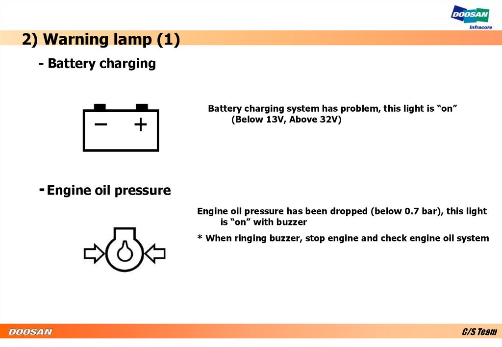
2) Warning lamp (1)- Battery charging
Battery charging system has problem, this light is “on”
(Below 13V, Above 32V)
- Engine oil pressure
Engine oil pressure has been dropped (below 0.7 bar), this light
is “on” with buzzer
* When ringing buzzer, stop engine and check engine oil system
C/S Team
9.
2) Warning lamp (2)- Coolant temperature
Overheat coolant, the light is “on” with buzzer
* When overheating, engine R.P.M is dropped to low
R.P.M.
- Check engine
Need checking engine, light is “on”
C/S Team
10.
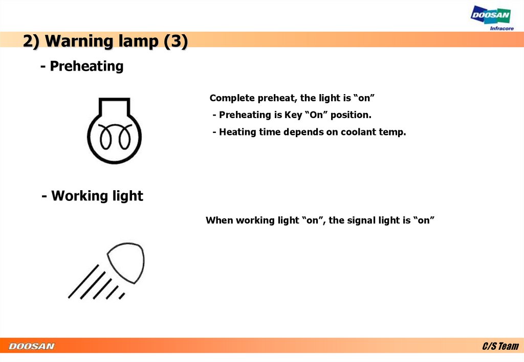
2) Warning lamp (3)- Preheating
Complete preheat, the light is “on”
- Preheating is Key “On” position.
- Heating time depends on coolant temp.
- Working light
When working light “on”, the signal light is “on”
C/S Team
11.
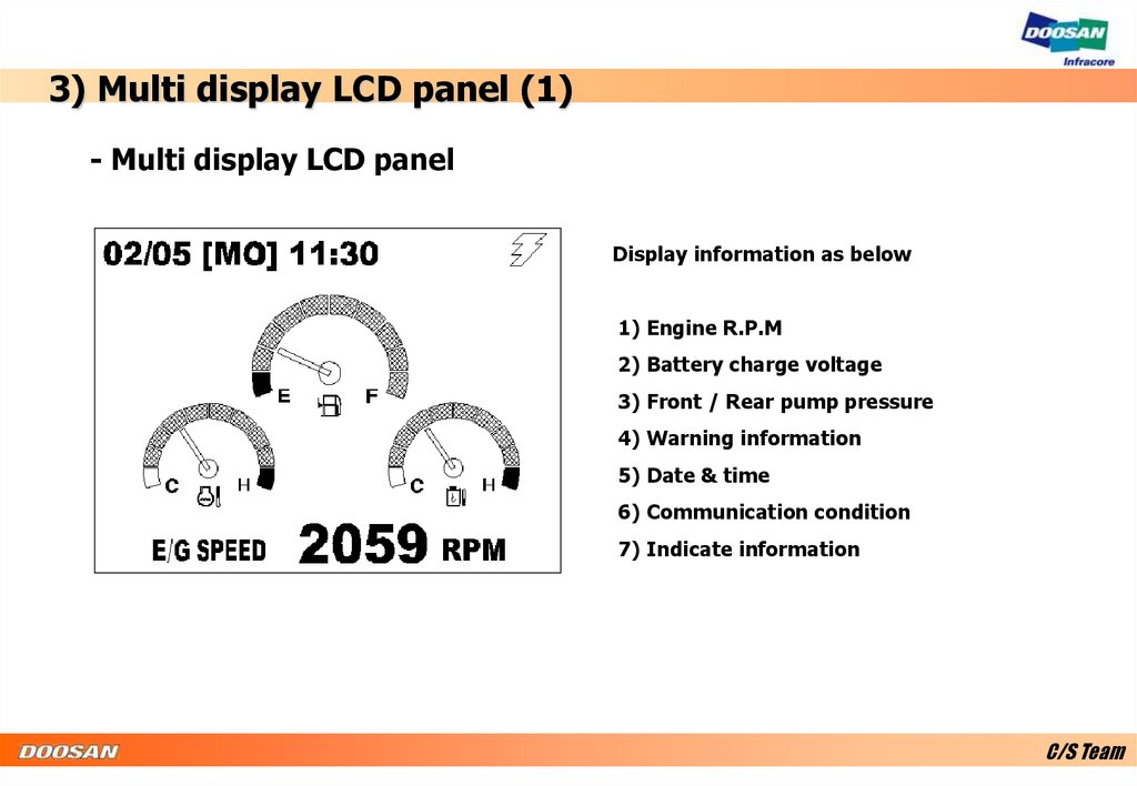
3) Multi display LCD panel (1)- Multi display LCD panel
Display information as below
1) Engine R.P.M
2) Battery charge voltage
3) Front / Rear pump pressure
4) Warning information
5) Date & time
6) Communication condition
7) Indicate information
C/S Team
12.
3) Multi display LCD panel (2)- Display communication condition
Display communication condition with E EOPS
- Display machine condition
E/G SPEED 2059 RPM
BATTEY
27.5 VOLT
Normal charging condition is 26~30 volt.
FRONT PUMP 320 BAR
REAR PUMP
313 BAR
C/S Team
13.
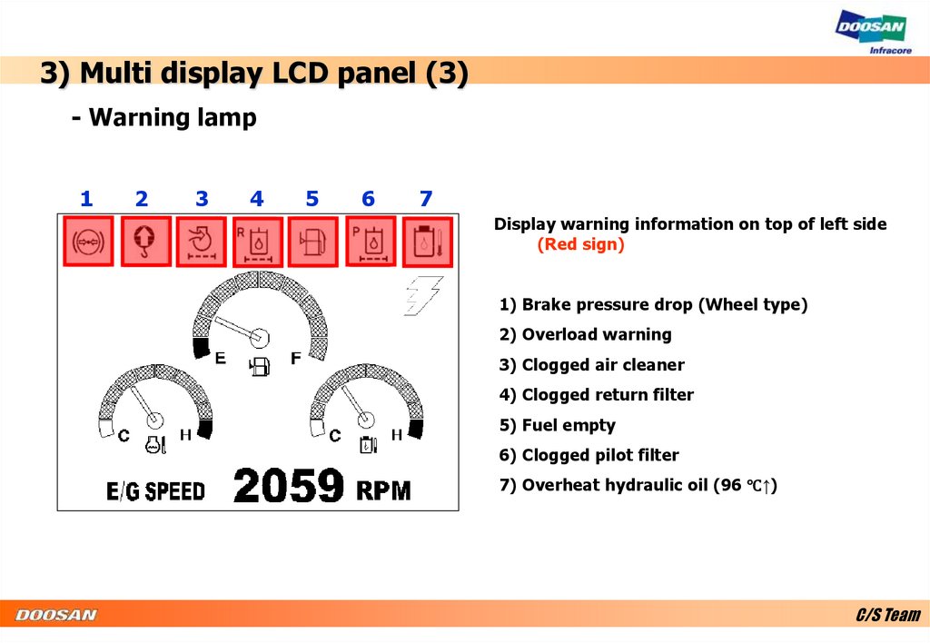
3) Multi display LCD panel (3)- Warning lamp
1
2
3
4
5
6
7
Display warning information on top of left side
(Red sign)
1) Brake pressure drop (Wheel type)
2) Overload warning
3) Clogged air cleaner
4) Clogged return filter
5) Fuel empty
6) Clogged pilot filter
7) Overheat hydraulic oil (96 ℃↑)
C/S Team
14.
3) Multi display LCD panel (4)- Indicate lamp
Display below switch condition (Green sign)
1) Pressure up
2) Breaker
3) Shear
4) Travel (Wheel)
C/S Team
15.
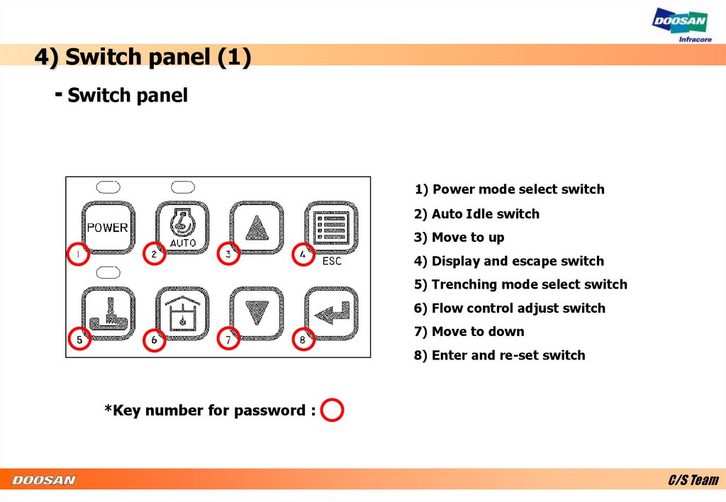
4) Switch panel (1)- Switch panel
1) Power mode select switch
2) Auto Idle switch
3) Move to up
4) Display and escape switch
5) Trenching mode select switch
6) Flow control adjust switch
7) Move to down
8) Enter and re-set switch
*Key number for password :
C/S Team
16.
4) Switch panel (2)- Power/Work mode switch
Power mode
- On : Power mode
- Off : Standard mode
* For heavy or fastworking
Trenching mode
- On : Trenching mode
- Off : Digging mode
* When start engine, set digging mode automatically
C/S Team
17.
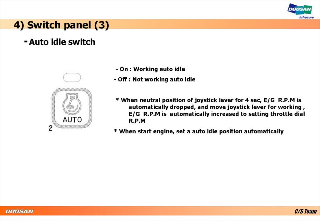
4) Switch panel (3)- Auto idle switch
- On : Working auto idle
- Off : Not working auto idle
* When neutral position of joystick lever for 4 sec, E/G R.P.M is
automatically dropped, and move joystick lever for working ,
E/G R.P.M is automatically increased to setting throttle dial
R.P.M
* When start engine, set a auto idle position automatically
C/S Team
18.
4) Switch panel (4)- Flow control switch
Adjusting flow for attachment as below
For breaker
For crusher
*Adjusting flow
Press
, adjust flow through
and
, and
to go first screen .
When use attachment, the flow is set by pervious setting flow.
C/S Team
19.
4) Switch panel (5)- Main menu
- Move cursor to up
or previous screen
- Move cursor to down
or next screen
- Display machine condition
or escape main menu
- Entering or re set
filter/oil using time
C/S Team
20.
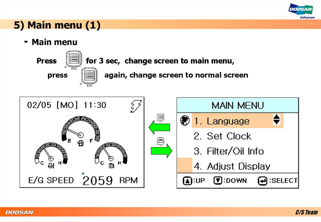
5) Main menu (1)- Main menu
Press
press
for 3 sec, change screen to main menu,
again, change screen to normal screen
C/S Team
21.
5) Main menu (2)- Language setting
Press
, set your language
through
and
.
Press
for 1 sec to escape.
C/S Team
22.
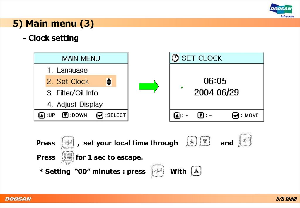
5) Main menu (3)- Clock setting
Press
, set your local time through
Press
for 1 sec to escape.
* Setting “00” minutes : press
and
.
With
C/S Team
23.
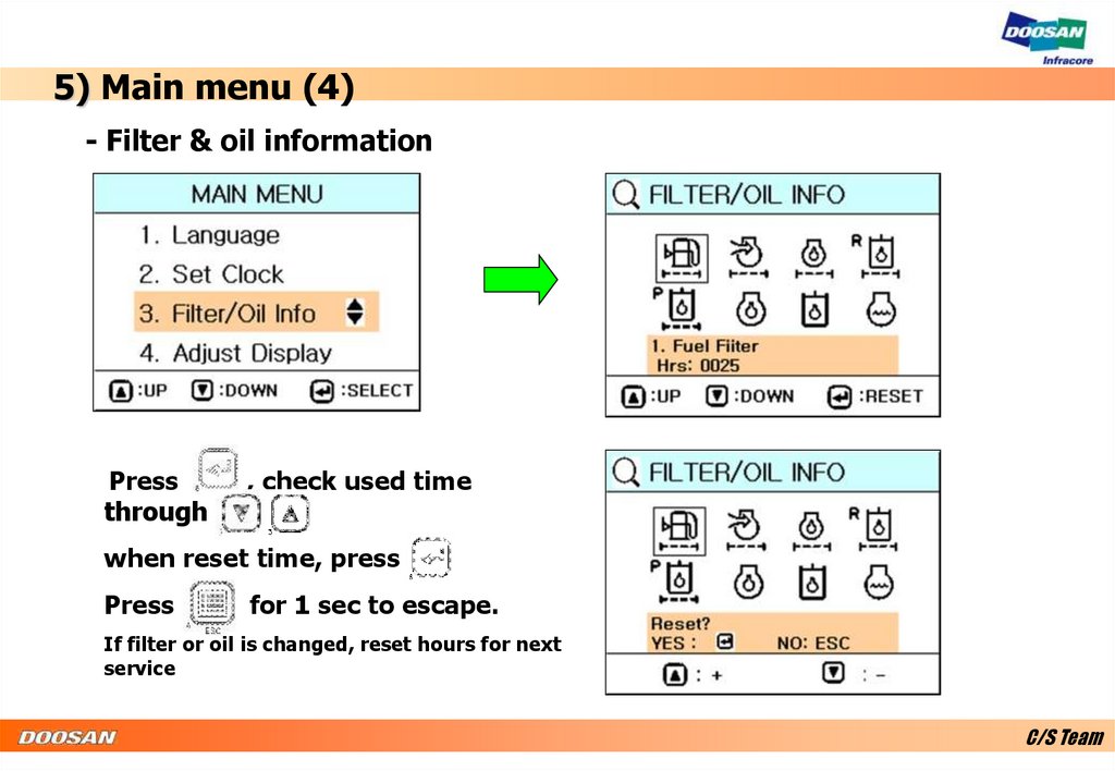
5) Main menu (4)- Filter & oil information
Press
through
, check used time
.
when reset time, press
Press
for 1 sec to escape.
If filter or oil is changed, reset hours for next
service
C/S Team
24.
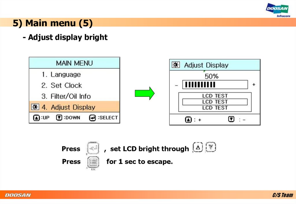
5) Main menu (5)- Adjust display bright
Press
, set LCD bright through
Press
for 1 sec to escape.
.
C/S Team
25.
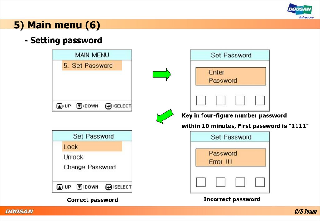
5) Main menu (6)- Setting password
Key in four-figure number password
within 10 minutes, First password is “1111”
Correct password
Incorrect password
C/S Team
26.
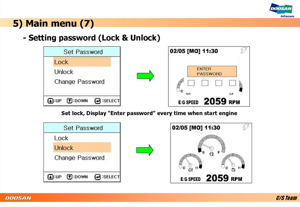
5) Main menu (7)- Setting password (Lock & Unlock)
Set lock, Display “Enter password” every time when start engine
C/S Team
27.
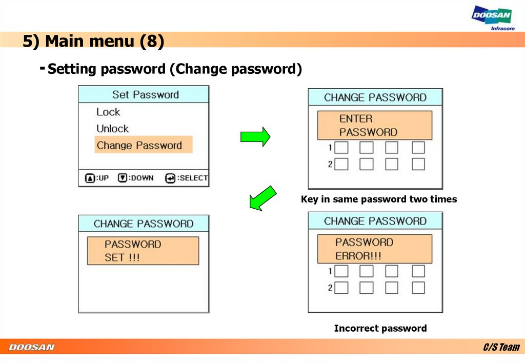
5) Main menu (8)- Setting password (Change password)
Key in same password two times
Incorrect password
C/S Team
28.
6) Special menu (1)- Special menu
Press
press
and
for 3 sec, change screen to special menu,
again, change screen to normal screen.
C/S Team
29.
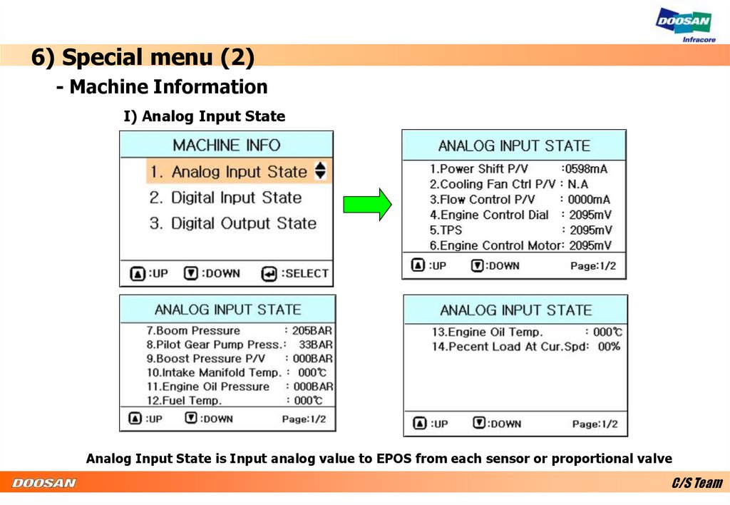
6) Special menu (2)- Machine Information
I) Analog Input State
Analog Input State is Input analog value to EPOS from each sensor or proportional valve
C/S Team
30.
6) Special menu (3)2) Machine Information
II) Digital Input State
Digital Input State is Input Digital signal ( On or Off) to EPOS from each switch
C/S Team
31.
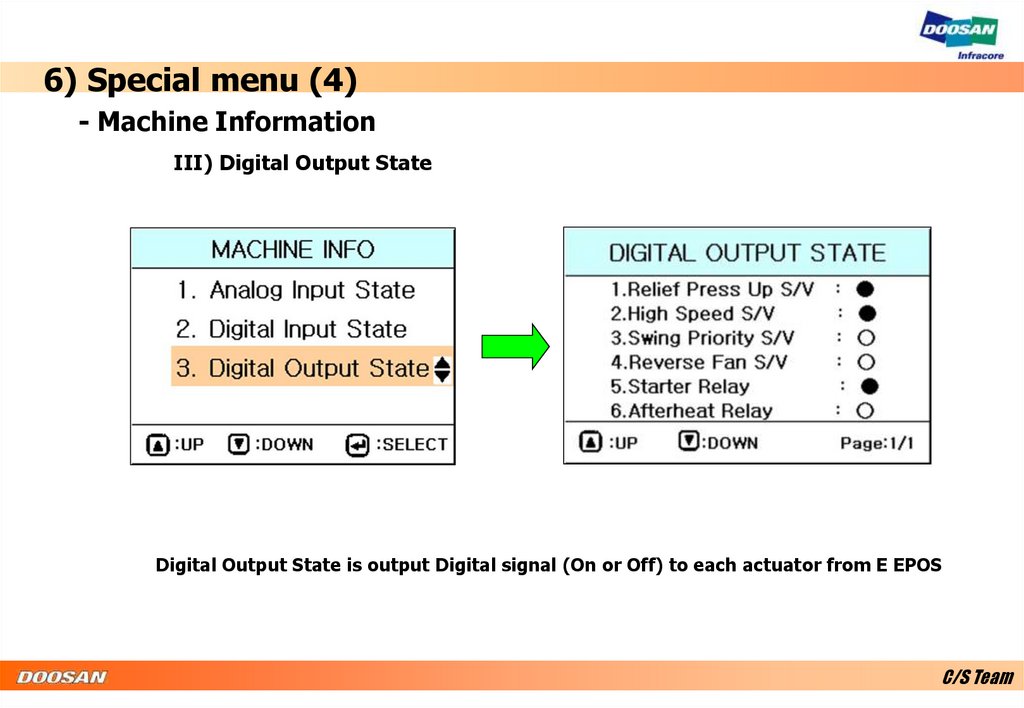
6) Special menu (4)- Machine Information
III) Digital Output State
Digital Output State is output Digital signal (On or Off) to each actuator from E EPOS
C/S Team
32.
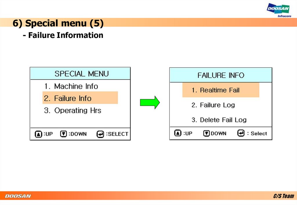
6) Special menu (5)- Failure Information
C/S Team
33.
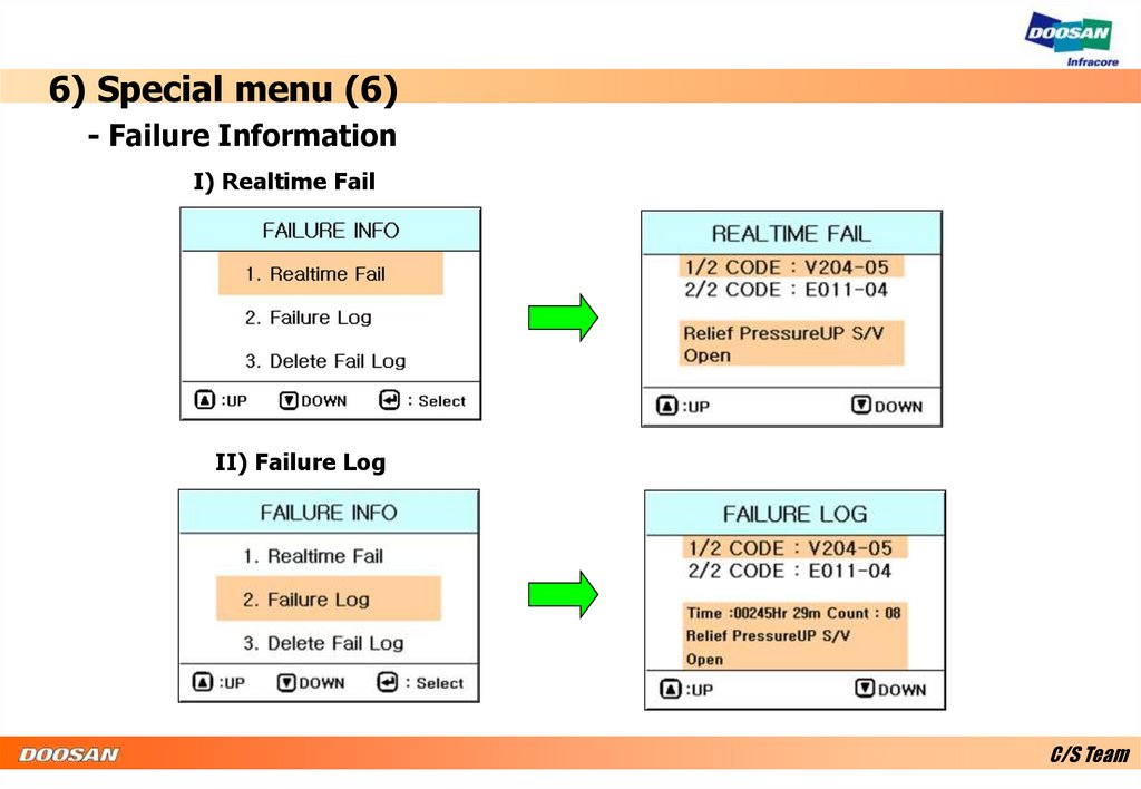
6) Special menu (6)- Failure Information
I) Realtime Fail
II) Failure Log
C/S Team
34.
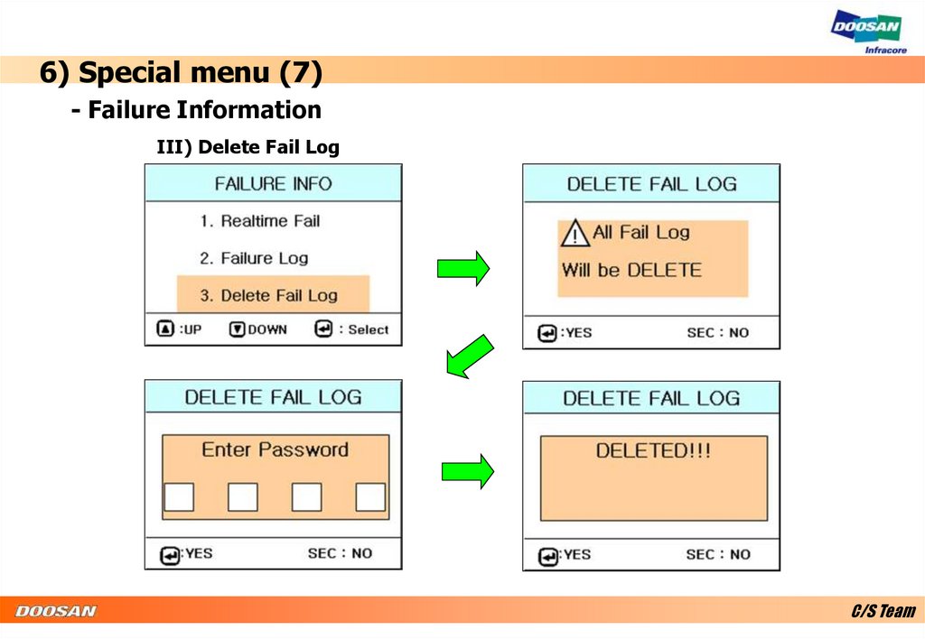
6) Special menu (7)- Failure Information
III) Delete Fail Log
C/S Team
35.
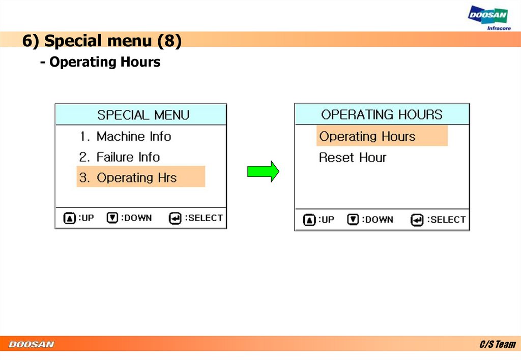
6) Special menu (8)- Operating Hours
C/S Team
36.
6) Special menu (9)- Operating Hours
I) Operating Hours
C/S Team
37.
6) Special menu (10)- Operating Hours
I) Reset Hour
C/S Team