


 Электроника
Похожие презентации:


Central Processing Unit
1.
Chapter 8: Central Processing UnitBCSC1005: Computer Organization
1
2. CENTRAL PROCESSING UNIT
• Introduction• General Register Organization
• Stack Organization
• Instruction Formats
• Addressing Modes
• Data Transfer and Manipulation
• Program Control
• Reduced Instruction Set Computer (RISC)
BCSC1005: Computer
Organization
2
3. MAJOR COMPONENTS OF CPU
Storage Components:Registers
Flip-flops
Execution (Processing) Components:
Arithmetic Logic Unit (ALU):
Arithmetic calculations, Logical computations, Shifts/Rotates
Transfer Components:
Bus
Control Components:
Control Unit
Register
File
ALU
Control Unit
BCSC1005: Computer
Organization
3
4. GENERAL REGISTER ORGANIZATION
InputClock
R1
R2
R3
R4
R5
R6
R7
Load
(7 lines)
SELA
{
3x8
decoder
MUX
MUX
A bus
SELD
OPR
} SELB
B bus
ALU
Output
BCSC1005: Computer
Organization
4
5. OPERATION OF CONTROL UNIT
The control unit directs the information flow through ALU by:- Selecting various Components in the system
- Selecting the Function of ALU
Example: R1 <- R2 + R3
[1] MUX A selector (SELA): BUS A R2
[2] MUX B selector (SELB): BUS B R3
[3] ALU operation selector (OPR): ALU to ADD
[4] Decoder destination selector (SELD): R1 Out Bus
3
SELA
3
SELB
3
SELD
Control Word
Encoding of register selection fields
5
OPR
Binary
Code
SELA
SELB
000
Input
Input
001
R1
R1
010
R2
R2
011
R3
R3
100
R4
R4
101
R5
R5
110
R6
R6
111
R7
R7
BCSC1005: Computer
Organization
SELD
None
R1
R2
R3
R4
R5
R6
R7
5
6. ALU CONTROL
ControlALU CONTROL
Encoding of ALU operations
OPR
Select
00000
00001
00010
00101
00110
01000
01010
01100
01110
10000
11000
Operation
Transfer A
Increment A
ADD A + B
Subtract A - B
Decrement A
AND A and B
OR A and B
XOR A and B
Complement A
Shift right A
Shift left A
Symbol
TSFA
INCA
ADD
SUB
DECA
AND
OR
XOR
COMA
SHRA
SHLA
Examples of ALU Microoperations
Symbolic Designation
Microoperation
SELA SELB
SELD
OPR
R1 R2 - R3
R4 R4 R5
R6 R6 + 1
R7 R1
Output R2
Output Input
R2
R4
R6
R1
R2
Input
R3
R5
-
R1
R4
R6
R7
None
None
SUB
OR
INCA
TSFA
TSFA
TSFA
010 011 001 00101
100 101 100 01010
110 000 110 00001
001 000 111 00000
010 000 000 00000
000 000 000 00000
R4 shl R4
R5 0
R4
R5
R5
R4
R5
SHLA
XOR
100 000 100 11000
101 101 101 01100
BCSC1005: Computer
Organization
Control Word
6
7. REGISTER STACK ORGANIZATION
Stack- Very useful feature for nested subroutines, nested loops control
- Also efficient for arithmetic expression evaluation
- Storage which can be accessed in LIFO
- Pointer: SP
- Only PUSH and POP operations are applicable
stack
Register Stack
63
Flags
FULL
Address
EMPTY
Stack pointer
SP
C
B
A
Push, Pop operations
4
3
2
1
0
DR
/* Initially, SP = 0, EMPTY = 1, FULL = 0 */
PUSH
SP SP + 1
M[SP] DR
If (SP = 0) then (FULL 1)
EMPTY 0
POP
DR M[SP]
SP SP - 1
If (SP = 0) then (EMPTY 1)
FULL 0
BCSC1005: Computer
Organization
7
8. MEMORY STACK ORGANIZATION
1000Memory with Program, Data,
and Stack Segments
PC
Program
(instructions)
AR
Data
(operands)
SP
- A portion of memory is used as a stack with a
processor register as a stack pointer
- PUSH:
- POP:
3000
stack
3997
3998
3999
4000
4001
DR
SP SP - 1
M[SP] DR
DR M[SP]
SP SP + 1
- Most computers do not provide hardware to check
stack overflow (full stack) or underflow(empty stack)
BCSC1005: Computer
Organization
8
9. REVERSE POLISH NOTATION
Arithmetic Expressions: A + BA+B
+AB
AB+
Infix notation
Prefix or Polish notation
Postfix or reverse Polish notation
- The reverse Polish notation is very suitable for stack
manipulation
Evaluation of Arithmetic Expressions
Any arithmetic expression can be expressed in parenthesis-free
Polish notation, including reverse Polish notation
(3 * 4) + (5 * 6)
34*56*+
3
4
3
12
5
12
6
5
12
3
4
*
5
6
30
12
42
*
+
BCSC1005: Computer
Organization
9
10.
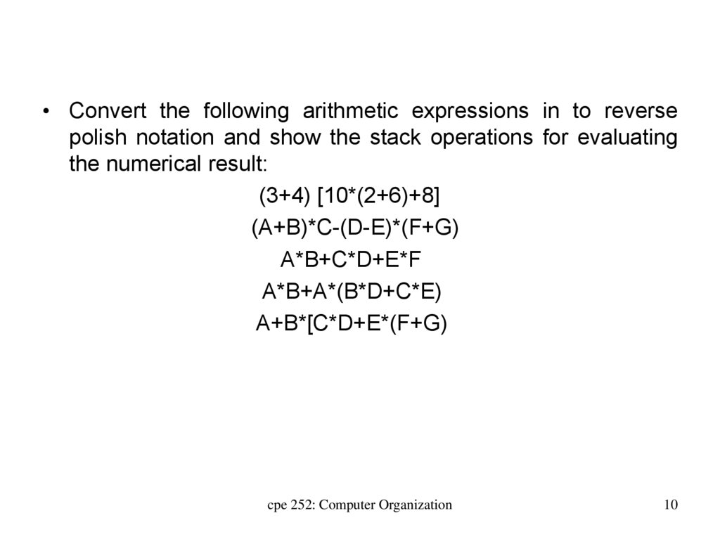
• Convert the following arithmetic expressions in to reversepolish notation and show the stack operations for evaluating
the numerical result:
(3+4) [10*(2+6)+8]
(A+B)*C-(D-E)*(F+G)
A*B+C*D+E*F
A*B+A*(B*D+C*E)
A+B*[C*D+E*(F+G)
cpe 252: Computer Organization
10
11. INSTRUCTION FORMAT
Instruction FormatINSTRUCTION FORMAT
Instruction Fields
OP-code field - specifies the operation to be performed
Address field - designates memory address(s) or a processor register(s)
Mode field
- specifies the way the operand or the
effective address is determined
The number of address fields in the instruction format
depends on the internal organization of CPU
- The three most common CPU organizations:
Single accumulator organization:
ADD
X
/* AC AC + M[X] */
General register organization:
ADD
R1, R2, R3
/* R1 R2 + R3 */
ADD
R1, R2
/* R1 R1 + R2 */
MOV R1, R2
/* R1 R2 */
ADD
R1, X
/* R1 R1 + M[X] */
Stack organization:
PUSH X
/* TOS M[X] */
ADD
BCSC1005: Computer
Organization
11
12. THREE, and TWO-ADDRESS INSTRUCTIONS
Three-Address Instructions:Program to evaluate X = (A + B) * (C + D) :
ADD R1, A, B
/* R1 M[A] + M[B]
ADD R2, C, D
/* R2 M[C] + M[D]
MUL X, R1, R2
/* M[X] R1 * R2
*/
*/
*/
- Results in short programs
- Instruction becomes long (many bits)
Two-Address Instructions:
Program to evaluate X = (A + B) * (C + D) :
MOV
ADD
MOV
ADD
MUL
MOV
R1, A
R1, B
R2, C
R2, D
R1, R2
X, R1
/* R1 M[A]
*/
/* R1 R1 + M[B] */
/* R2 M[C]
*/
/* R2 R2 + M[D] */
/* R1 R1 * R2
*/
/* M[X] R1
*/
BCSC1005: Computer
Organization
12
13. ONE, and ZERO-ADDRESS INSTRUCTIONS
One-Address Instructions:- Use an implied AC register for all data manipulation
- Program to evaluate X = (A + B) * (C + D) :
LOAD
A
/* AC M[A]
ADD
B
/* AC AC + M[B]
STORE
T
/* M[T] AC
LOAD
C
/* AC M[C]
ADD
D
/* AC AC + M[D]
MUL
T
/* AC AC * M[T]
STORE
X
/* M[X] AC
*/
*/
*/
*/
*/
*/
*/
Zero-Address Instructions:
- Can be found in a stack-organized computer
- Program to evaluate X = (A + B) * (C + D) :
PUSH
A
/* TOS A
*/
PUSH
B
/* TOS B
*/
ADD
/* TOS (A + B)
*/
PUSH
C
/* TOS C
*/
PUSH
D
/* TOS D
*/
ADD
/* TOS (C + D)
*/
MUL
/* TOS (C + D) * (A + B) */
POP
X
/* M[X] TOS
*/
BCSC1005: Computer
Organization
13
14. ADDRESSING MODES
Addressing Modes:* Specifies a rule for interpreting or modifying the
address field of the instruction (before the operand
is actually referenced)
* Variety of addressing modes
- to give programming flexibility to the user
- to use the bits in the address field of the
instruction efficiently
BCSC1005: Computer
Organization
14
15. TYPES OF ADDRESSING MODES
Implied ModeAddress of the operands are specified implicitly
in the instruction
- No need to specify address in the instruction
- Ex: CMA(Complement the accumulator)
Immediate Mode
Instead of specifying the address of the operand,
the instruction contains the operand itself.
Direct Address Mode
Instruction specifies the memory address which
can be used directly to get the operand.
Indirect Addressing Mode
The address field of an instruction specifies the address of a
memory location that contains the address of the operand.
cpe 252: Computer Organization
15
16. TYPES OF ADDRESSING MODES
Register ModeAddress specified in the instruction is the register address
Register Indirect Mode
Instruction specifies a register which contains the memory address of
operand
the
Auto-increment
Same as the Register Indirect, but when the address in the register is used to access
memory, the value in the register is incremented after the execution of the
instruction.
Auto-decrement features:
Same as the Register Indirect, but when the address in the register is used to
access memory, the value in the register is decremented before the execution of the
instruction.
cpe 252: Computer Organization
16
17. TYPES OF ADDRESSING MODES
Relative Addressing ModesThe Address fields of an instruction specifies the part of the address
(abbreviated address) which can be used along with a PC to calculate the address of
the operand
EA = PC + IR(address)
- Address field of the instruction is short
- Large physical memory can be accessed with a small number of
address bits
Indexed Addressing Mode
XR: Index Register:
- EA = XR + IR(address)
Base Register Addressing Mode
BAR: Base Address Register:
- EA = BAR + IR(address)
cpe 252: Computer Organization
17
18. ADDRESSING MODES - EXAMPLES
AddressPC = 200
Memory
200
201
202
Load to AC Mode
Address = 500
Next instruction
399
400
450
700
500
800
600
900
702
325
800
300
R1 = 400
XR = 100
AC
Addressing
Effective
Mode
Address
Direct address
500
Immediate operand Indirect address
800
Relative address
702
Indexed address
600
Register
Register indirect
400
Autoincrement
400
Autodecrement
399
Content
of AC
/* AC (500)
*/
800
/* AC 500
*/
500
/* AC ((500))
*/
300
/* AC (PC+500) */
325
/* AC (XR+500) */
900
/* AC R1
*/
400
/* AC (R1)
*/
700
/* AC (R1)+
*/
700
/* AC -(R)
*/
450
BCSC1005: Computer
Organization
18
19.
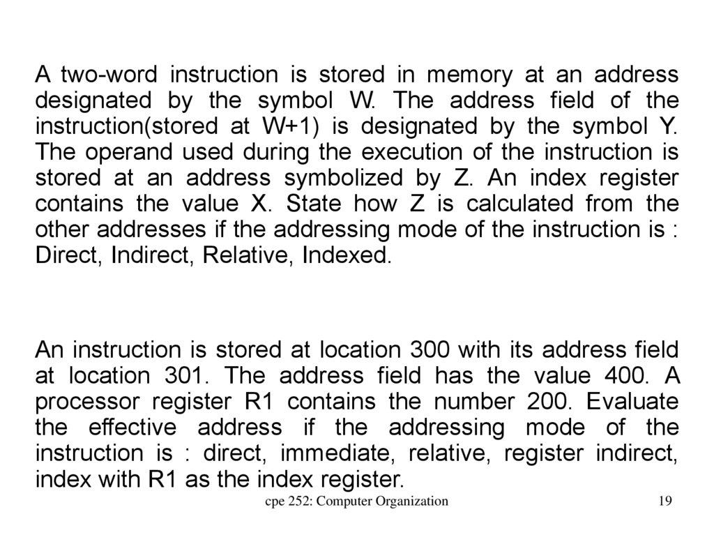
A two-word instruction is stored in memory at an addressdesignated by the symbol W. The address field of the
instruction(stored at W+1) is designated by the symbol Y.
The operand used during the execution of the instruction is
stored at an address symbolized by Z. An index register
contains the value X. State how Z is calculated from the
other addresses if the addressing mode of the instruction is :
Direct, Indirect, Relative, Indexed.
An instruction is stored at location 300 with its address field
at location 301. The address field has the value 400. A
processor register R1 contains the number 200. Evaluate
the effective address if the addressing mode of the
instruction is : direct, immediate, relative, register indirect,
index with R1 as the index register.
cpe 252: Computer Organization
19