


 Информатика
Похожие презентации:


Installation Requirements
1.
NW6000 TRAININGModule 2 – Installation Requirements
2.
NW6000 – INSTALLATION REQUIREMENTS2
3.
NW6000 – INSTALLATION REQUIREMENTSIMO 2014 PERFORMANCE STANDARDS
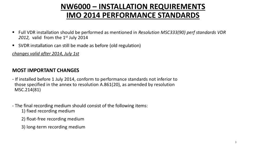
Full VDR installation should be performed as mentioned in Resolution MSC333(90) perf standards VDR
2012, valid from the 1st July 2014
SVDR installation can still be made as before (old regulation)
changes valid after 2014, July 1st
MOST IMPORTANT CHANGES
- If installed before 1 July 2014, conform to performance standards not inferior to
those specified in the annex to resolution A.861(20), as amended by resolution
MSC.214(81)
- The final recording medium should consist of the following items:
1) fixed recording medium
2) float-free recording medium
3) long-term recording medium
3
4.
NW6000 – INSTALLATION REQUIREMENTSIMO 2014 PERFORMANCE STANDARDS
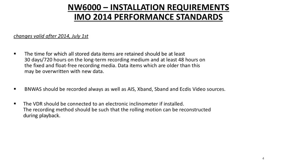
changes valid after 2014, July 1st
The time for which all stored data items are retained should be at least
30 days/720 hours on the long-term recording medium and at least 48 hours on
the fixed and float-free recording media. Data items which are older than this
may be overwritten with new data.
BNWAS should be recorded always as well as AIS, Xband, Sband and Ecdis Video sources.
The VDR should be connected to an electronic inclinometer if installed.
The recording method should be such that the rolling motion can be reconstructed
during playback.
4
5.
NW6000 – INSTALLATION REQUIREMENTSIMO 2014 PERFORMANCE STANDARDS
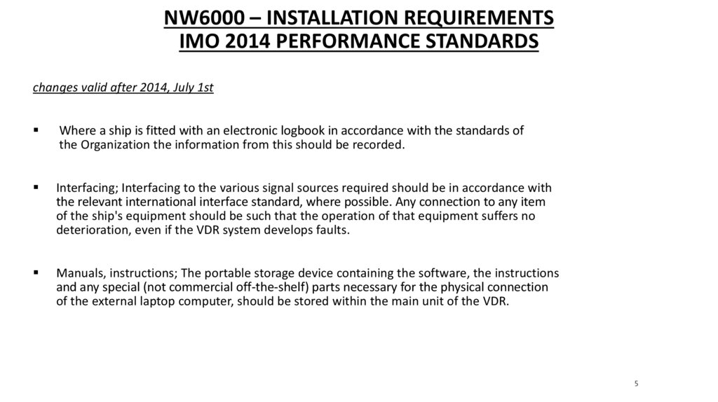
changes valid after 2014, July 1st
Where a ship is fitted with an electronic logbook in accordance with the standards of
the Organization the information from this should be recorded.
Interfacing; Interfacing to the various signal sources required should be in accordance with
the relevant international interface standard, where possible. Any connection to any item
of the ship's equipment should be such that the operation of that equipment suffers no
deterioration, even if the VDR system develops faults.
Manuals, instructions; The portable storage device containing the software, the instructions
and any special (not commercial off-the-shelf) parts necessary for the physical connection
of the external laptop computer, should be stored within the main unit of the VDR.
5
6.
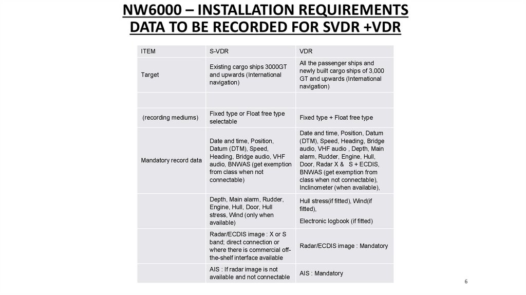
NW6000 – INSTALLATION REQUIREMENTSDATA TO BE RECORDED FOR SVDR +VDR
ITEM
S-VDR
VDR
Target
Existing cargo ships 3000GT
and upwards (International
navigation)
All the passenger ships and
newly built cargo ships of 3,000
GT and upwards (International
navigation)
(recording mediums)
Fixed type or Float free type
selectable
Fixed type + Float free type
Date and time, Position,
Datum (DTM), Speed,
Heading, Bridge audio, VHF
audio, BNWAS (get exemption
from class when not
connectable)
Date and time, Position, Datum
(DTM), Speed, Heading, Bridge
audio, VHF audio , Depth, Main
alarm, Rudder, Engine, Hull,
Door, Radar X & S + ECDIS,
BNWAS (get exemption from
class when not connectable),
Inclinometer (when available),
Mandatory record data
Depth, Main alarm, Rudder,
Engine, Hull, Door, Hull
stress, Wind (only when
available)
Hull stress(if fitted), Wind(if
fitted),
Electronic logbook (if fitted)
Radar/ECDIS image : X or S
band; direct connection or
where there is commercial offthe-shelf interface available
Radar/ECDIS image : Mandatory
AIS : If radar image is not
available and not connectable
AIS : Mandatory
6
7.
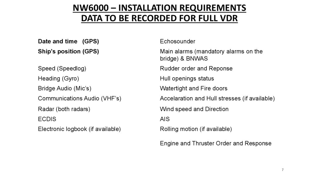
NW6000 – INSTALLATION REQUIREMENTSDATA TO BE RECORDED FOR FULL VDR
Date and time (GPS)
Echosounder
Ship’s position (GPS)
Main alarms (mandatory alarms on the
bridge) & BNWAS
Speed (Speedlog)
Rudder order and Reponse
Heading (Gyro)
Hull openings status
Bridge Audio (Mic’s)
Watertight and Fire doors
Communications Audio (VHF’s)
Accelaration and Hull stresses (if available)
Radar (both radars)
Wind speed and Direction
ECDIS
AIS
Electronic logbook (if available)
Rolling motion (if available)
Engine and Thruster Order and Response
7
8.
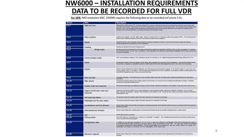
NW6000 – INSTALLATION REQUIREMENTSDATA TO BE RECORDED FOR FULL VDR
For VDR, IMO resolution MSC. 333(90) requires the following data to be recorded (ref article 5.5):
Article
Data
Description
5.5.1
Date and time
Date and time, referenced to UTC, should be obtained from a source external to the ship and an internal clock should be synchronized with
valid date and time data. During times of a loss of the external source, the internal clock should be used. The recording should indicate which
source is in use. The recording method should be such that the timing of all other recorded data items can be derived on playback with a
resolution and continuity sufficient to reconstruct the history of the incident in detail.
5.5.2
Ship’s position
Latitude and longitude, and the datum used, should be derived from an electronic position-fixing system (EPFS). The recording should
ensure that the identity and status of the EPFS can always be determined on playback.
5.5.3
Speed
Speed through the water and speed over the ground, including an indication of which it is, derived from the ship's speed and distance
measuring equipment, as required by SOLAS regulations.
5.5.4
5.5.5
Heading
5.5.6
Communication audio
VHF communications relating to ship operations should be recorded on an additional separate channel to those referred to in 5.5.5.
5.5.7
Radar
The electronic signals of the main displays of both ship's radar installations as required by SOLAS regulations. The recording method should
be such that, on playback, it is possible to present a faithful replica of the entire radar display that was on view at the time of recording,
5.5.8
ECDIS
Where a vessel is fitted with an ECDIS installation, the VDR should record the electronic signals of the ECDIS display in use at the time
as the primary means of navigation. The recording method should be such that, on playback, it is possible to present a faithful replica of the
entire ECDIS display that was on view at the time of recording
5.5.9
Echo sounder
5.5.10
Main alarms
The depth information. This should include, where available, depth under keel, the depth scale currently being displayed and other status
information.
This should include the status of all mandatory alarms on the bridge2 or as received from the Bridge Alert Management System, if installed,
recorded as individually identified alarms.
5.5.11
Rudder order and response
This should include status and settings of heading or track controller, if fitted and indicate the control station, mode, and power unit(s) in use
5.5.12
Engine and thruster order and
response
This should include the positions of any engine telegraphs or direct engine/propeller controls and feedback indications on the bridge, if
fitted, including ahead/astern indicators and indicate the control station in use. This should also include any thrusters if fitted and indicate the
control station in use.
5.5.13
Hull openings status
This should include all mandatory status information required to be displayed on the bridge.
5.5.14
Watertight and fire door status
This should include all mandatory status information required to be displayed on the bridge
5.5.15
Accelerations and hull stresses
Where a ship is fitted with hull stress and response monitoring equipment, all the data items that have been pre-selected within that equipment
should be recorded.
5.5.16
Wind speed and direction
Where a ship is fitted with a suitable sensor, wind speed and direction should be recorded, including its true or relative status.
5.5.17
5.5.18
AIS
Rolling motion
All AIS data should be recorded.
5.5.19
Configuration data
In addition to the data items specified in 5.5.1 to 5.5.18, a data block defining the configuration of the VDR and the sensors to which it
is connected should be written into the final recording medium during commissioning of the VDR. The data block should be maintained
up to date with respect to the vessel installation. It should include details on the manufacturer, type and version number of a sensor, the
identification and location of the sensor and the interpretation of the sensor data.
5.5.20
Electronic logbook
Where a ship is fitted with an electronic logbook in accordance with the standards of the Organization the information from this should be
recorded.
Heading as indicated by the ship's heading source.
Bridge audio
Microphones should be positioned on the bridge covering all work stations as described in MSC/Circ.982 so that conversation is recorded.
The recording should be such that, on playback, a normal speaking voice should provide adequate intelligibility while the ship is performing
its normal operations.
The VDR should be connected to an electronic inclinometer if installed.
can be reconstructed during playback.
The recording method should be such that the rolling motion
8
9.
NW6000 – MANDATORY DOCUMENTS, DATA AND DRAWINGSAFTER INSTALLATION
To provide optimal warranty support, it is essential that after installation the following data set will be
provided to Netwave Systems:
Overview/drawing of the Bridge/wheelhouse/monkey deck
Connection sheet mentioning the connected signals to specific inputs
All configuration files including vidchan’s (video configuration files)
Data sample from Core module containing 5 minutes with sound check
NW6000-90 VDR Commissioning PT and TA Certificate, filled in signed by the installer
Programming report TRON40VDR capsule (EPIRB report PRU40 or 50)
Photographs from all installed units and cabling/connections
Photographs from PSU batteries, outside expiry sticker, PT9-ninety label, Jotron labelling, HRU
Warranty will only be applied on those cases when above mentioned data is provided
after commissioning of the system.
TO BE SEND TO: netwavesystems.wetransfer.com
Note: find examples and the NW6000-90 VDR Commissioning PT and TA Certificate in folder APT &
Commissioning
9
10.
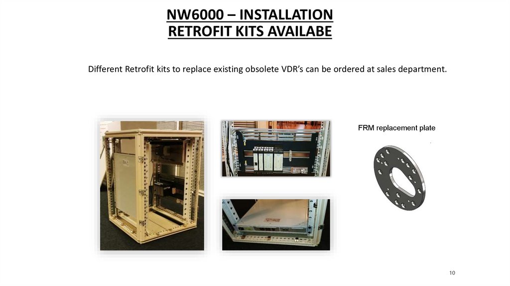
NW6000 – INSTALLATIONRETROFIT KITS AVAILABE
Different Retrofit kits to replace existing obsolete VDR’s can be ordered at sales department.
FRM replacement plate
10
11.
QUESTIONS?11
12.
NW6000 – MANDATORY DOCUMENTS, DATA AND DRAWINGSAFTER INSTALLATION
All cabling should be made with tension relief and fixed to the vessel approved CAT6/7 cabling should be used
only and can be pre ordered via Netwave-Loose cabling and bad made connectors or connections will not be
excepted!
all inputs on the signal cabling (NMEA, DIGI etc) should be labeled on the inputs of the adapter or hardware
device referring to an overview which is mentioning and explaining were the signal is coming from and leading
to.
single line drawings should be made about positions from the mic’s and connected equipment on the bridge,
as well an overview of the monkey deck were the capsule’s FRM & FFRM are located
photographs should be made and send to Netwave to prove that the installation is made in a right and proper
way.
certified engineer should explain afterwards to the cpt how the system is operating and can be checked (OPT),
a demonstration is required, the instruction video as well all the s/w in order to make a download should be
left on board.
if all above mentioned actions are not be taken or not according installation instructions by Netwave, warranty
will not be given, and all additional costs made in a later condition will be presented to the installer!!
12
13.
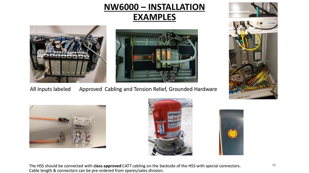
NW6000 – INSTALLATIONEXAMPLES
All inputs labeled
Approved Cabling and Tension Relief, Grounded Hardware
The HSS should be connected with class approved CAT7 cabling on the backside of the HSS with special connectors.
Cable length & connectors can be pre-ordered from spares/sales division.
13
14.
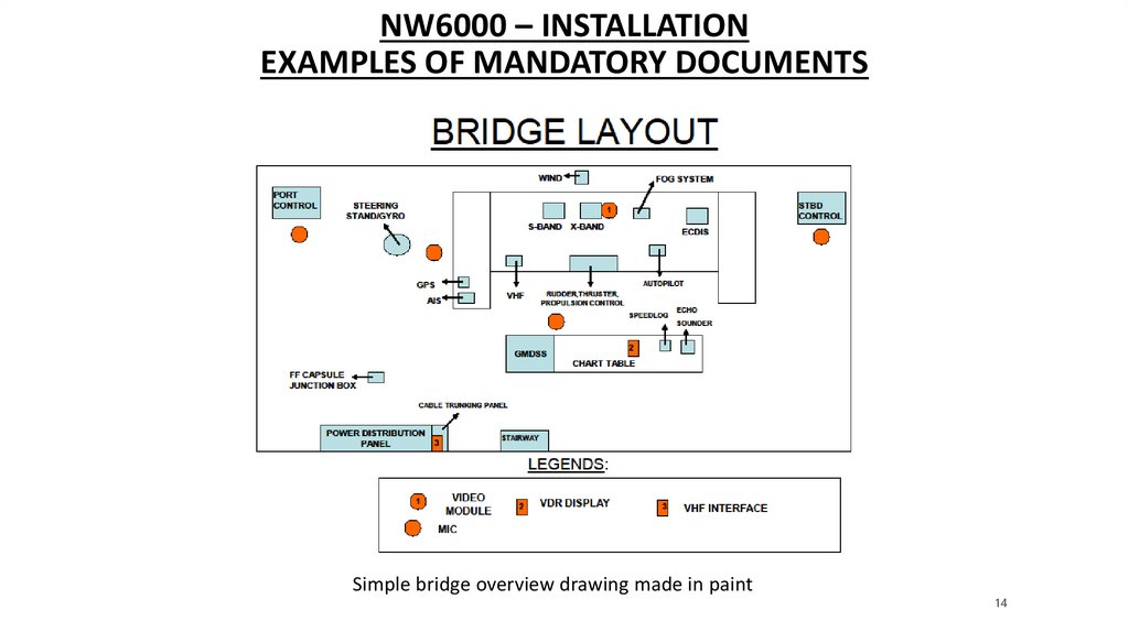
NW6000 – INSTALLATIONEXAMPLES OF MANDATORY DOCUMENTS
Simple bridge overview drawing made in paint
14
15.
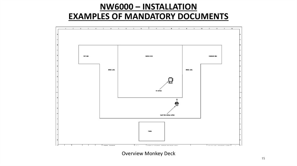
NW6000 – INSTALLATIONEXAMPLES OF MANDATORY DOCUMENTS
Overview Monkey Deck
15
16.
NW6000 – INSTALLATIONEXAMPLES OF MANDATORY DOCUMENTS
Overview connections
Jotron programming report
16
17.
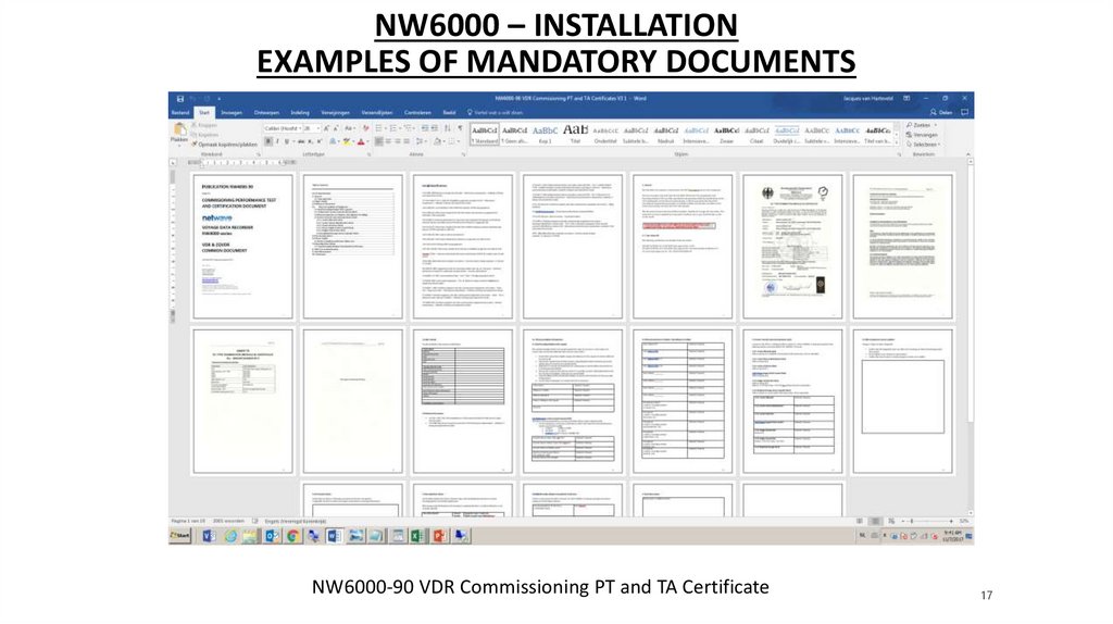
NW6000 – INSTALLATIONEXAMPLES OF MANDATORY DOCUMENTS
NW6000-90 VDR Commissioning PT and TA Certificate
17
18.
QUESTIONS?18