


 Информатика
Похожие презентации:


")

")


Connect to the VDR
1.
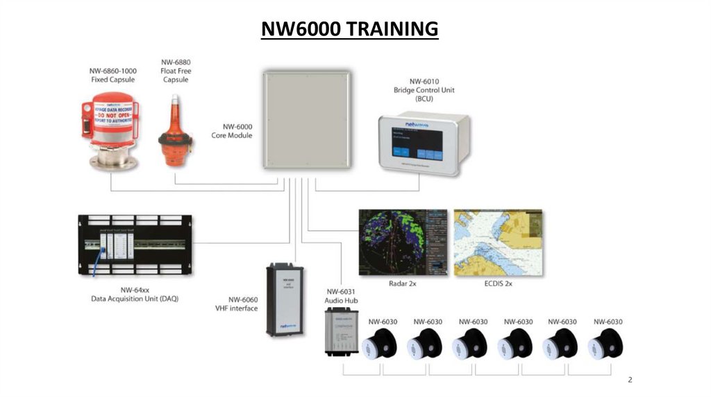
NW6000 TRAININGModule 5 – Configuring the VDR
2.
NW6000 TRAINING2
3.
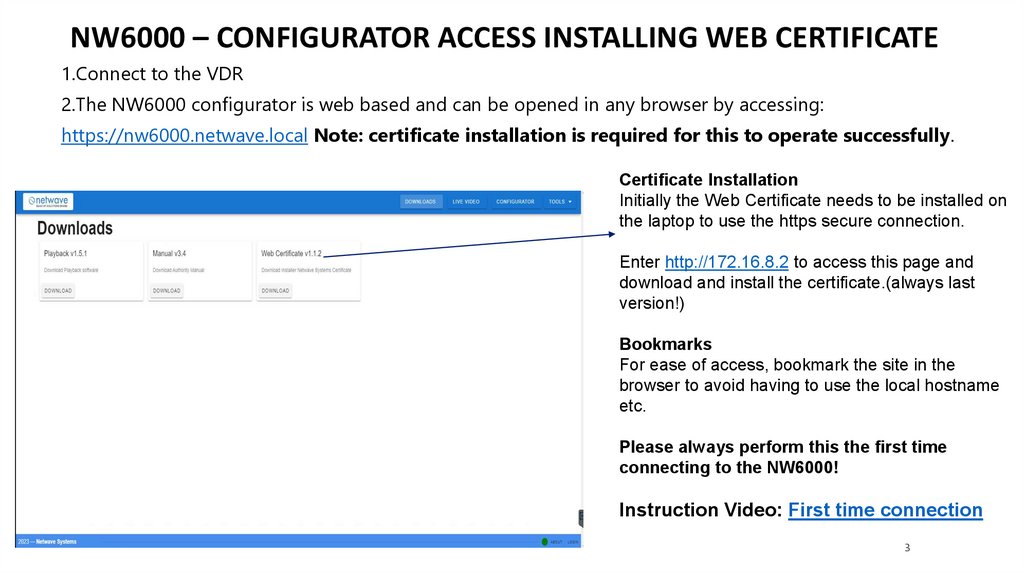
NW6000 – CONFIGURATOR ACCESS INSTALLING WEB CERTIFICATE1.Connect to the VDR
2.The NW6000 configurator is web based and can be opened in any browser by accessing:
https://nw6000.netwave.local Note: certificate installation is required for this to operate successfully.
Certificate Installation
Initially the Web Certificate needs to be installed on
the laptop to use the https secure connection.
Enter http://172.16.8.2 to access this page and
download and install the certificate.(always last
version!)
Bookmarks
For ease of access, bookmark the site in the
browser to avoid having to use the local hostname
etc.
Please always perform this the first time
connecting to the NW6000!
Instruction Video: First time connection
3
4.
NW6000 – DASHBOARD PAGEOn this page you will be able to download the playback software and to start applications.
Playback v2
manual for authorities
Live playing
Analyser
Video
+ BAM
live signals
Configuration set up
(Install on vessel’s connected computer
as well)
4
5.
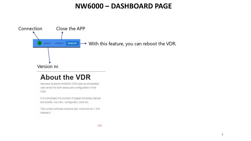
NW6000 – DASHBOARD PAGEConnection
Close the APP
With this feature, you can reboot the VDR.
Version nr.
5
6.
NW6000 – DASHBOARD PAGEThis tool will show live all incoming connected NMEA data.
The buttons in the left menu from top to down have the
following functionality.
Refresh
clears the list and continues to scan.
Pause
freezes updates to analyse table
Stop
stops the analyser
Disable alerts
timeouts for successive sentences are
displayed in red
Instruction video: NMEA Analyzer
6
7.
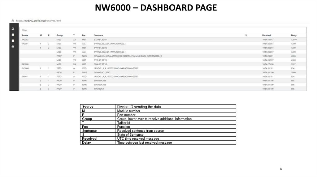
NW6000 – DASHBOARD PAGEThis tool will show live all incoming connected NMEA data.
The buttons in the left menu from top to down have the
following functionality.
Refresh
clears the list and continues to scan.
Pause
freezes updates to analyse table
Stop
stops the analyser
Disable alerts
timeouts for successive sentences are
displayed in red
Instruction video: NMEA Analyzer
7
8.
NW6000 – DASHBOARD PAGE8
9.
NW6000 – DASHBOARD PAGEThis BAM tool monitors, in real time, BAM
alert messages and displays them in a list.
The BAM Interface specification contains
a list with ID’s and description.
9
10.
NW6000 – DASHBOARD PAGEThe buttons in the left menu from top to down have the following
functionality.
Refresh clears BAM table.
Stop stops receiving BAM messages.
10
11.
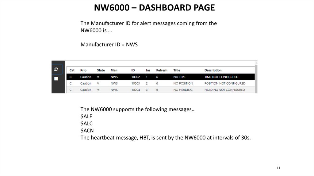
NW6000 – DASHBOARD PAGEThe Manufacturer ID for alert messages coming from the
NW6000 is …
Manufacturer ID = NWS
The NW6000 supports the following messages…
$ALF
$ALC
$ACN
The heartbeat message, HBT, is sent by the NW6000 at intervals of 30s.
11
12.
NW6000 – DASHBOARD PAGEThe description of the alert identifiers (ID) coming from the NW6000 are as follows:
Note: A second ALF message always accompanies the first message and contains additional channel information.
12
13.
NW6000 – CONFIGURATOR LOGINWhen opening the
configurator a username
and password is required.
Username: admin
Password: netwave
Don’t provide this
on board it’s for
tech’s only!!
Green = Connected
Red = Not Connected
13
14.
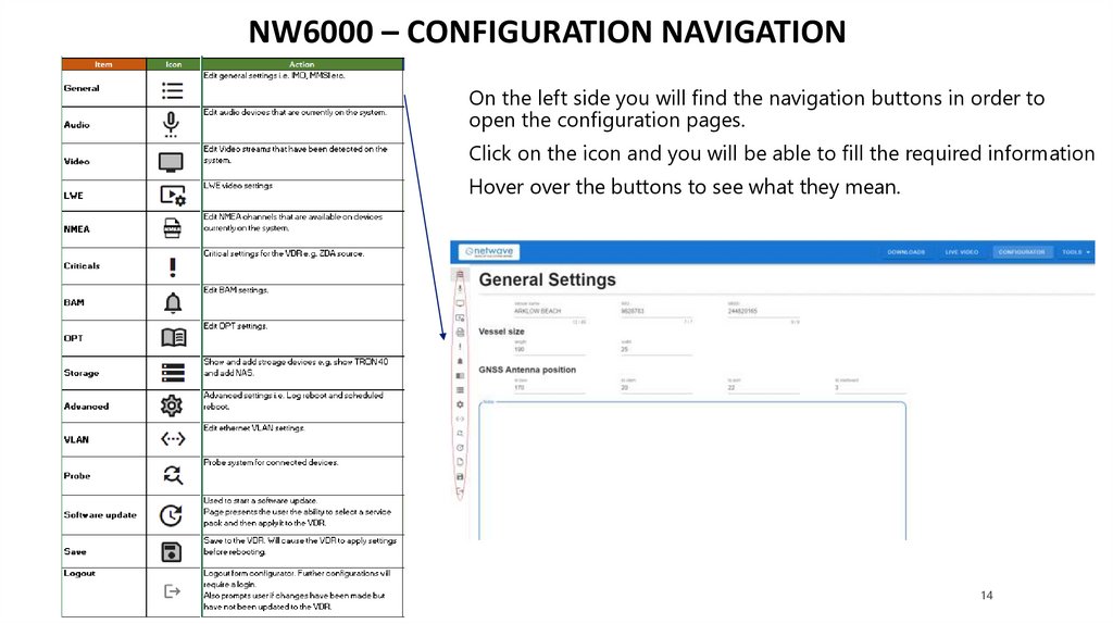
NW6000 – CONFIGURATION NAVIGATIONOn the left side you will find the navigation buttons in order to
open the configuration pages.
Click on the icon and you will be able to fill the required information
Hover over the buttons to see what they mean.
14
15.
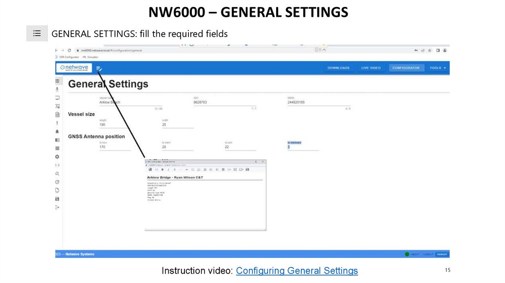
NW6000 – GENERAL SETTINGSGENERAL SETTINGS: fill the required fields
Instruction video: Configuring General Settings
15
16.
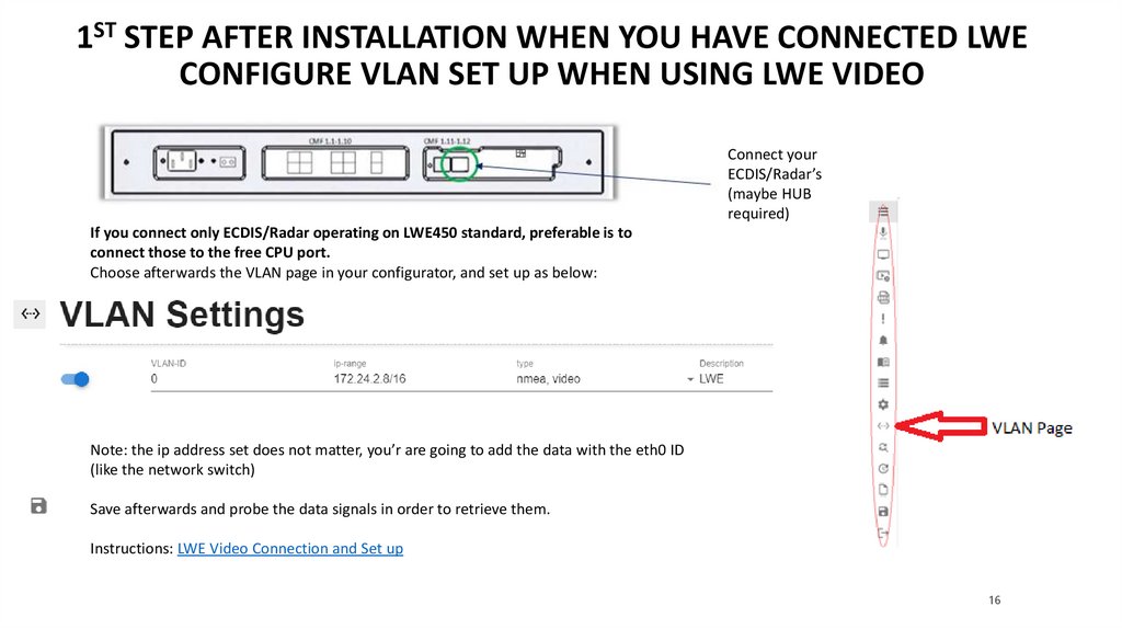
1ST STEP AFTER INSTALLATION WHEN YOU HAVE CONNECTED LWECONFIGURE VLAN SET UP WHEN USING LWE VIDEO
Connect your
ECDIS/Radar’s
(maybe HUB
required)
If you connect only ECDIS/Radar operating on LWE450 standard, preferable is to
connect those to the free CPU port.
Choose afterwards the VLAN page in your configurator, and set up as below:
Note: the ip address set does not matter, you’r are going to add the data with the eth0 ID
(like the network switch)
Save afterwards and probe the data signals in order to retrieve them.
Instructions: LWE Video Connection and Set up
16
17.
NW6000 - CONFIGURATORSTEPS AFTER INSTALLING EQUIPMENT, PROBE/SCAN
Connect to the VDR, be sure that the connection is active
Open probe,
Press scan,
the VDR will start searching for connected devices.
Detected Hardware
If some hardware is not detected, run the probe again.
17
18.
NW6000 - CONFIGURATORSTEPS AFTER INSTALLING EQUIPMENT
Press,
, system will scan for connected devices.
The configurator will import the found Devices, and list them as New Devices
Select
or, doubleclick on the ones you like to use only.
18
19.
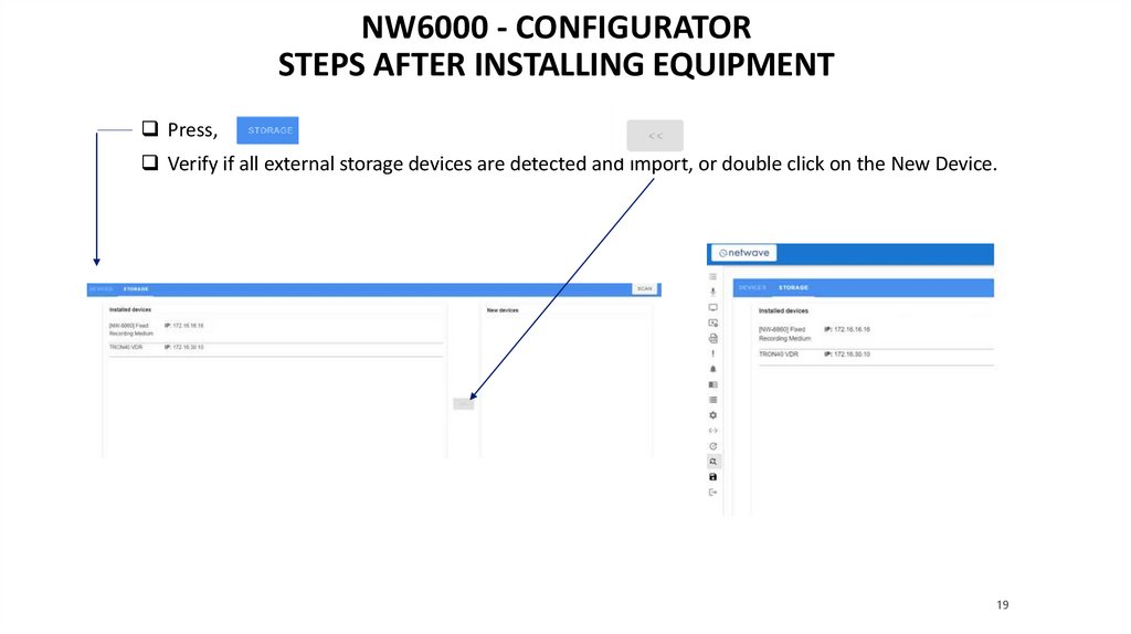
NW6000 - CONFIGURATORSTEPS AFTER INSTALLING EQUIPMENT
Press,
Verify if all external storage devices are detected and import, or double click on the New Device.
19
20.
NW6000 - CONFIGURATORSTEPS AFTER INSTALLING EQUIPMENT
Save,
Now you can continue with configuring, just click on an icon.
Instruction video: Probe Devices
20
21.
NW6000 - DEVICES AND NAMESThe configurator will be showing all connected devices which can be individually configured.
Opening the created cm config file (as text) you will find the devices.Explanation of the names:
PN400X.X
Microphones (analogue)
PN1XXX
Microphones (digital)
PN400X
Audio HUB
PN2000 – PN2999
VHF
PN500x
BCU
SI600x
Data acquisition modules(DAQ)
MODULES
SIM1 - BUSCOUPLER
SIMx - NMEA MODULE
DIMx – DIGITAL MODULE
AIMx – ANALOGUE MODULE
RMS = PN7000
HSS(FRM)
RV0001
Video Module
JOTRON
TRON40 FFRM
ECxxxx
connected ECDIS via LWE
Raxxxx
connected Radar via LWE
INxxxx
connected Video via LWE
21
22.
NW6000 – CONFIGURATION FILESAfter the probe the found devices with their ip’s on the probe page, will be shown
When all devices are found, it should be merged inside the VDR this will create cm-config.json
select: save
The main VDR configuration file = cm-config.json this will be used when the VDR is rebooted.
Note: probe is only used for adding or replacing devices afterwards
22
23.
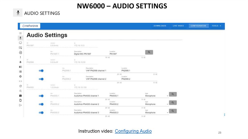
AUDIO SETTINGSNW6000 – AUDIO SETTINGS
Instruction video: Configuring Audio
23
24.
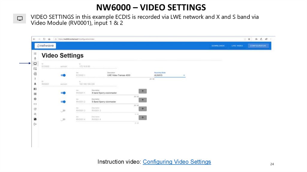
NW6000 – VIDEO SETTINGSVIDEO SETTINGS in this example ECDIS is recorded via LWE network and X and S band via
Video Module (RV0001), input 1 & 2
Instruction video: Configuring Video Settings
24
25.
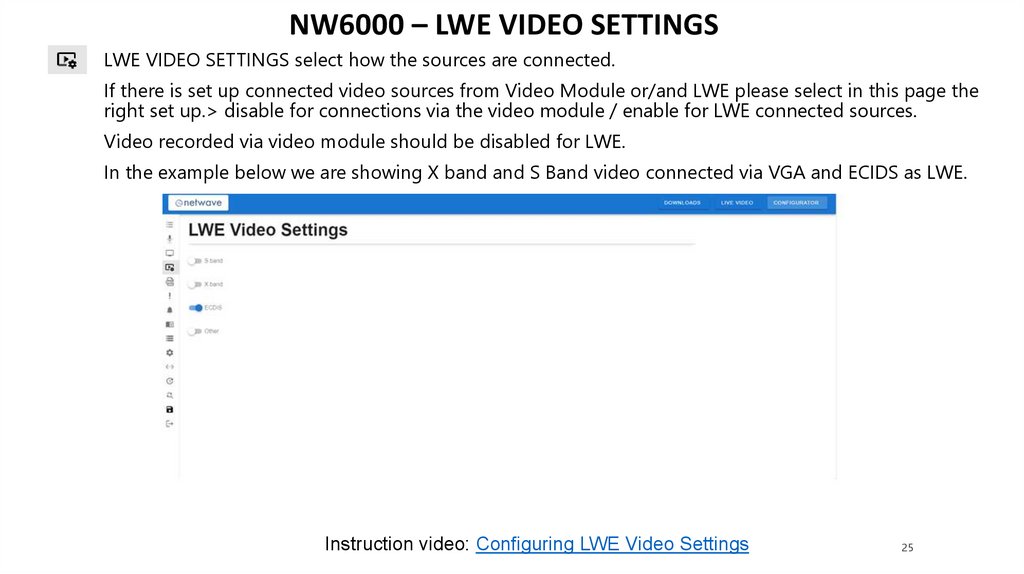
NW6000 – LWE VIDEO SETTINGSLWE VIDEO SETTINGS select how the sources are connected.
If there is set up connected video sources from Video Module or/and LWE please select in this page the
right set up.> disable for connections via the video module / enable for LWE connected sources.
Video recorded via video module should be disabled for LWE.
In the example below we are showing X band and S Band video connected via VGA and ECIDS as LWE.
Instruction video: Configuring LWE Video Settings
25
26.
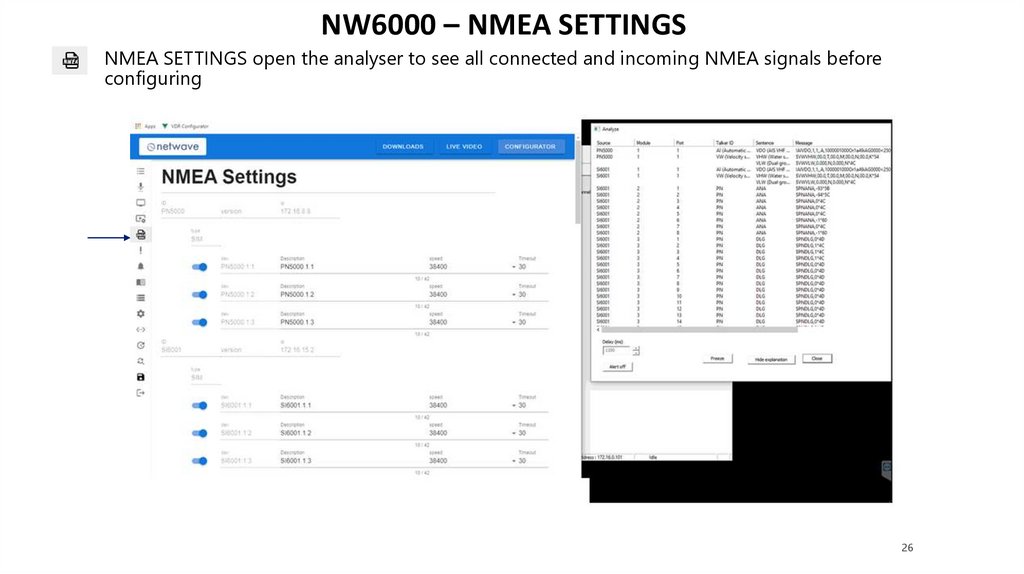
NW6000 – NMEA SETTINGSNMEA SETTINGS open the analyser to see all connected and incoming NMEA signals before
configuring
26
27.
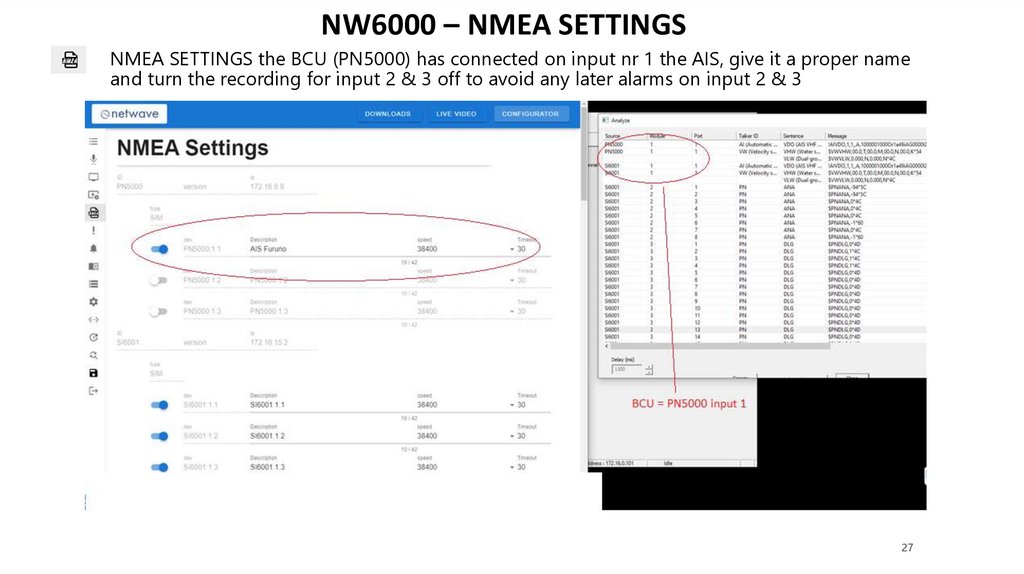
NW6000 – NMEA SETTINGSNMEA SETTINGS the BCU (PN5000) has connected on input nr 1 the AIS, give it a proper name
and turn the recording for input 2 & 3 off to avoid any later alarms on input 2 & 3
27
28.
NW6000 – NMEA SETTINGSNMEA SETTINGS the Buscoupler (PN600X) has connected on input nr 1 also an AIS signal in this
example, when the signal is live it will show itself in the Analyzer, give it a proper name, input 2 & 3
are not connected and not shown, so disable them!
28
29.
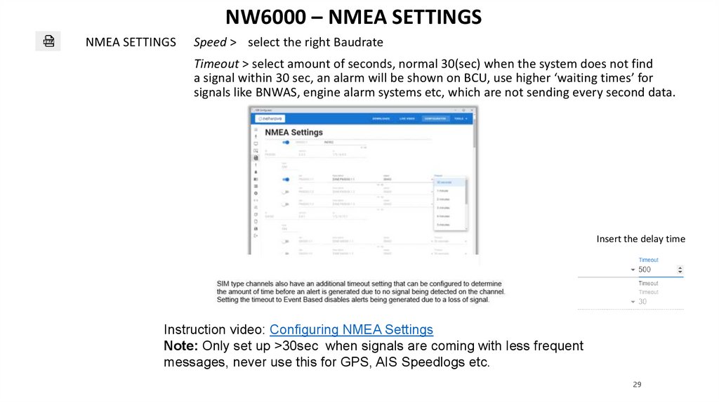
NW6000 – NMEA SETTINGSNMEA SETTINGS
Speed > select the right Baudrate
Timeout > select amount of seconds, normal 30(sec) when the system does not find
a signal within 30 sec, an alarm will be shown on BCU, use higher ‘waiting times’ for
signals like BNWAS, engine alarm systems etc, which are not sending every second data.
Insert the delay time
Instruction video: Configuring NMEA Settings
Note: Only set up >30sec when signals are coming with less frequent
messages, never use this for GPS, AIS Speedlogs etc.
29
30.
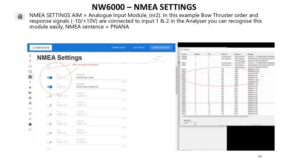
NW6000 – NMEA SETTINGSNMEA SETTINGS AIM = Analogue Input Module, (nr2). In this example Bow Thruster order and
response signals (-10/+10V) are connected to input 1 & 2 in the Analyser you can recognise this
module easily, NMEA sentence = PNANA
30
31.
NW6000 – NMEA SETTINGSNMEA SETTINGS AIM = Analogue Input Module, (nr2). In this example Bow Thruster order and
response signals (-10/+10V) are connected to input 1 & 2 with
you can configure what should be
displayed in the OPT on the BCU
When opened set up the
found calibration points
e.g. Bowthruster
31
32.
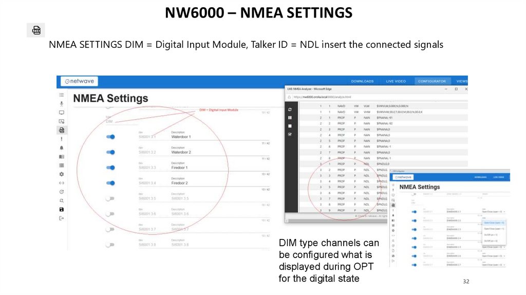
NW6000 – NMEA SETTINGSNMEA SETTINGS DIM = Digital Input Module, Talker ID = NDL insert the connected signals
DIM type channels can
be configured what is
displayed during OPT
for the digital state
32
33.
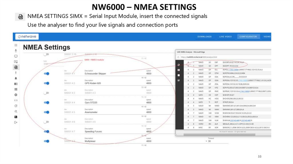
NW6000 – NMEA SETTINGSNMEA SETTINGS SIMX = Serial Input Module, insert the connected signals
Use the analyser to find your live signals and connection ports
33
34.
NW6000 – CRITICAL SETTINGSCRITICAL SETTINGS = sensors used by the VDR to provide alarm warnings in case the dat is not
been received.
Further, the system can and will accept Glonass/GPS
(“GN”) and Glonass (“GL”) receiver messages, to be filled
at the Talker ID.
Instruction video: Configuring Critical Settings
34
35.
NW6000 – BAM SETTINGSBAM SETTINGS = Bridge Alarm Management Settings, if NMEA can be connected to the central bridge
alarm system you can choose which connection is applied, Default = Network // Serial = NMEA
connection
NMEA connections can be made from free ports on BCU or BusCoupler.
Use a free port on BCU PN5000.1 /2 or 3 or BusCoupler free port PN600X.1 /2 or 3
Examples:
35
36.
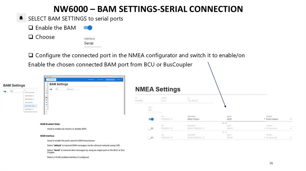
NW6000 – BAM SETTINGS-SERIAL CONNECTIONSELECT BAM SETTINGS to serial ports
Enable the BAM
Choose
Configure the connected port in the NMEA configurator and switch it to enable/on
Enable the chosen connected BAM port from BCU or BusCoupler
36
37.
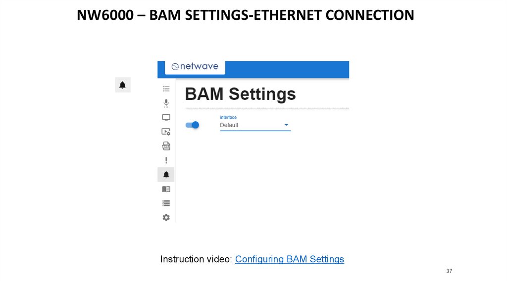
NW6000 – BAM SETTINGS-ETHERNET CONNECTIONInstruction video: Configuring BAM Settings
37
38.
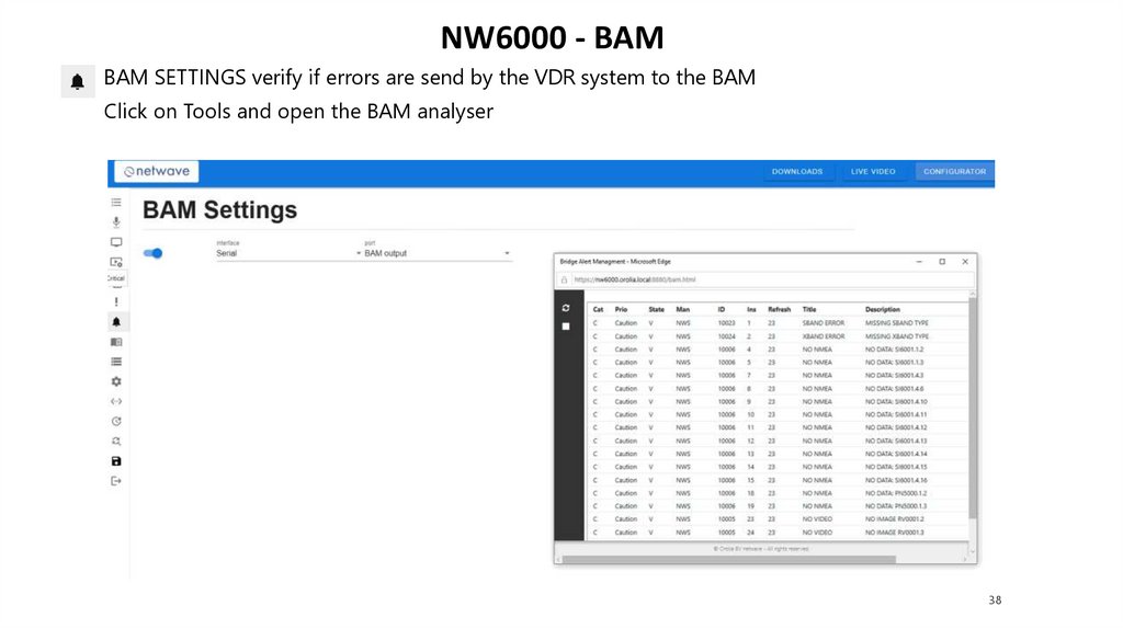
NW6000 - BAMBAM SETTINGS verify if errors are send by the VDR system to the BAM
Click on Tools and open the BAM analyser
38
39.
NW6000 – OPT SETTINGSOPT = Operational Performance Test.
To enable these tests on the system configuration is required for NMEA, Audio and Video.
Create Groups or categories, click add first category
39
40.
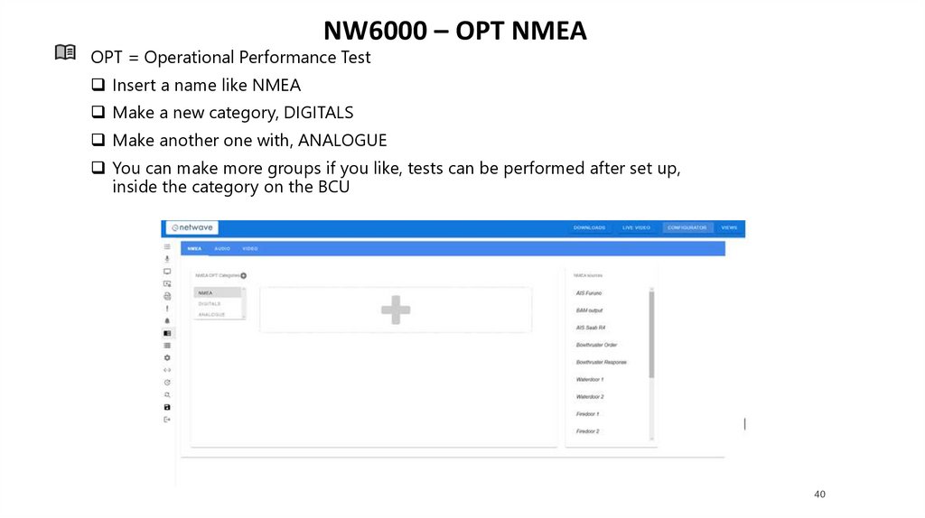
NW6000 – OPT NMEAOPT = Operational Performance Test
Insert a name like NMEA
Make a new category, DIGITALS
Make another one with, ANALOGUE
You can make more groups if you like, tests can be performed after set up,
inside the category on the BCU
40
41.
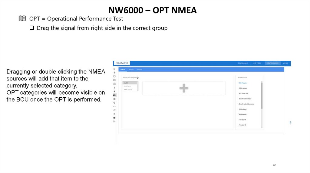
NW6000 – OPT NMEAOPT = Operational Performance Test
Drag the signal from right side in the correct group
Dragging or double clicking the NMEA
sources will add that item to the
currently selected category.
OPT categories will become visible on
the BCU once the OPT is performed.
41
42.
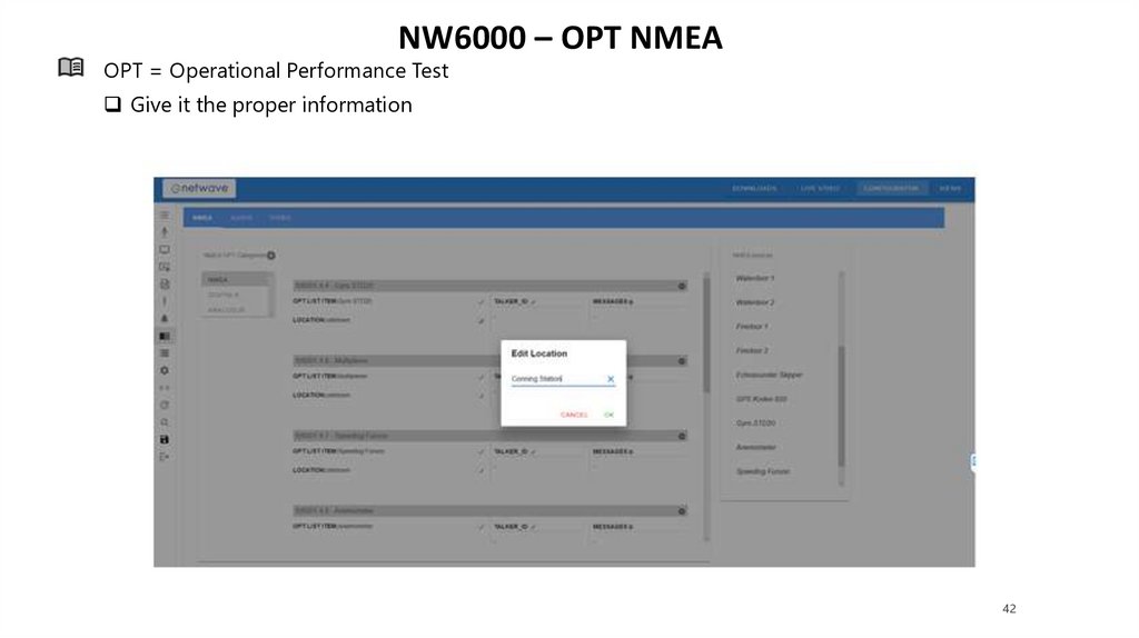
NW6000 – OPT NMEAOPT = Operational Performance Test
Give it the proper information
42
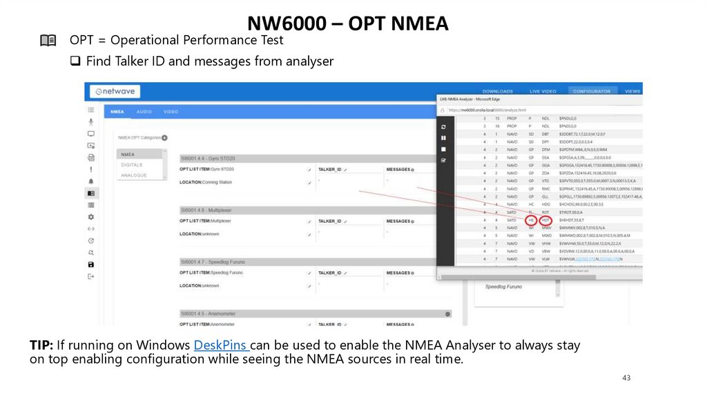
43.
NW6000 – OPT NMEAOPT = Operational Performance Test
Find Talker ID and messages from analyser
TIP: If running on Windows DeskPins can be used to enable the NMEA Analyser to always stay
on top enabling configuration while seeing the NMEA sources in real time.
43
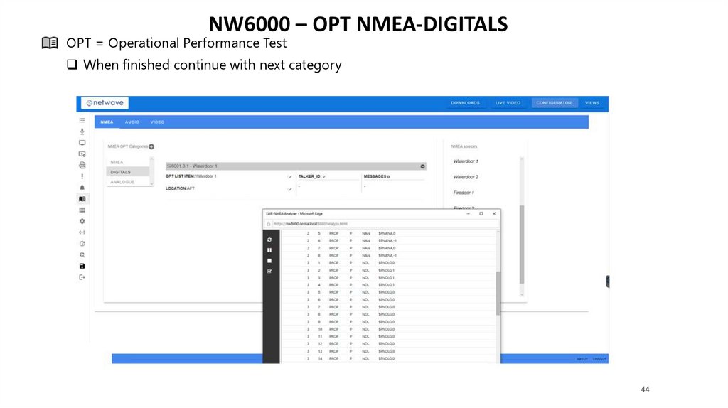
44.
NW6000 – OPT NMEA-DIGITALSOPT = Operational Performance Test
When finished continue with next category
44
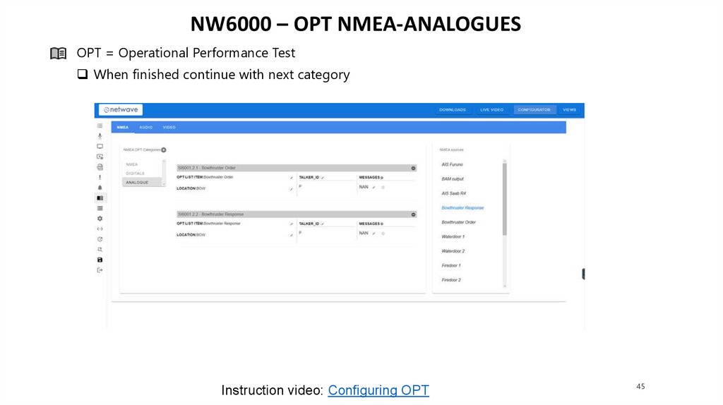
45.
NW6000 – OPT NMEA-ANALOGUESOPT = Operational Performance Test
When finished continue with next category
Instruction video: Configuring OPT
45
46.
NW6000 – EXTERNAL STORAGE SETTINGSEXT = External Storage Settings
This page will provide information regarding connected recording media
46
47.
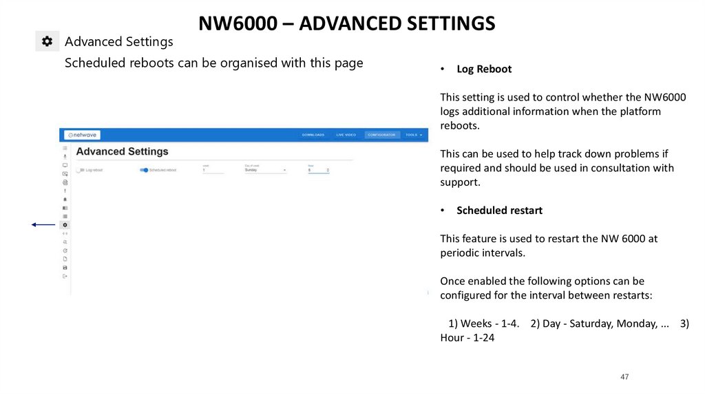
Advanced SettingsNW6000 – ADVANCED SETTINGS
Scheduled reboots can be organised with this page
Log Reboot
This setting is used to control whether the NW6000
logs additional information when the platform
reboots.
This can be used to help track down problems if
required and should be used in consultation with
support.
Scheduled restart
This feature is used to restart the NW 6000 at
periodic intervals.
Once enabled the following options can be
configured for the interval between restarts:
1) Weeks - 1-4. 2) Day - Saturday, Monday, ... 3)
Hour - 1-24
47
48.
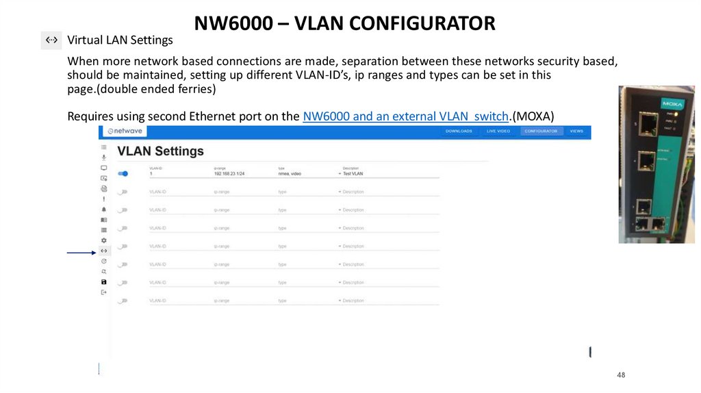
Virtual LAN SettingsNW6000 – VLAN CONFIGURATOR
When more network based connections are made, separation between these networks security based,
should be maintained, setting up different VLAN-ID’s, ip ranges and types can be set in this
page.(double ended ferries)
Requires using second Ethernet port on the NW6000 and an external VLAN switch.(MOXA)
48
49.
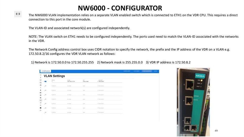
NW6000 - CONFIGURATORThe NW6000 VLAN implementation relies on a separate VLAN enabled switch which is connected to ETH1 on the VDR CPU. This requires a direct
connection to this port in the core module.
The VLAN-ID and associated network(s) are configured independently.
NOTE: The VLAN switch on ETH1 needs to be configured independently. The ports used need to match the VLAN-ID associated with the networks
in the VDR.
The Network Config address control box uses CIDR notation to specify the network, the prefix and the IP address of the VDR on a VLAN e.g.
172.50.8.2/16 configures the VDR VLAN network as follows:
1) Network is 172.50.0.0 to 172.50.255.255 2) Network mask is 255.255.0.0 3) VDR IP address is 172.50.8.2
49
50.
NW6000 - CONFIGURATORConnect to
additional
programmable
MOXA
NW6000 VLAN Configuration
50
51.
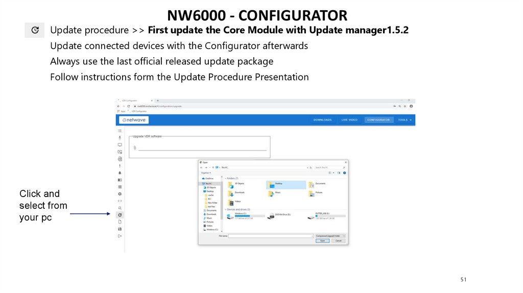
NW6000 - CONFIGURATORUpdate procedure >> First update the Core Module with Update manager1.5.2
Update connected devices with the Configurator afterwards
Always use the last official released update package
Follow instructions form the Update Procedure Presentation
Click and
select from
your pc
51
52.
Update procedureNW6000 - CONFIGURATOR
Video: Update Procedure
52
53.
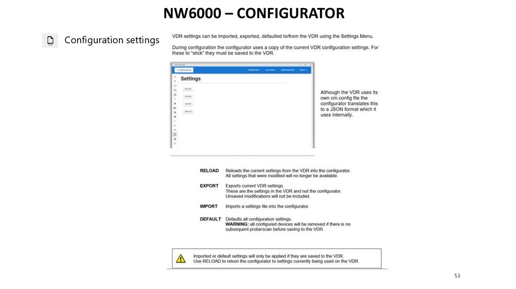
NW6000 – CONFIGURATORConfiguration settings
53
54.
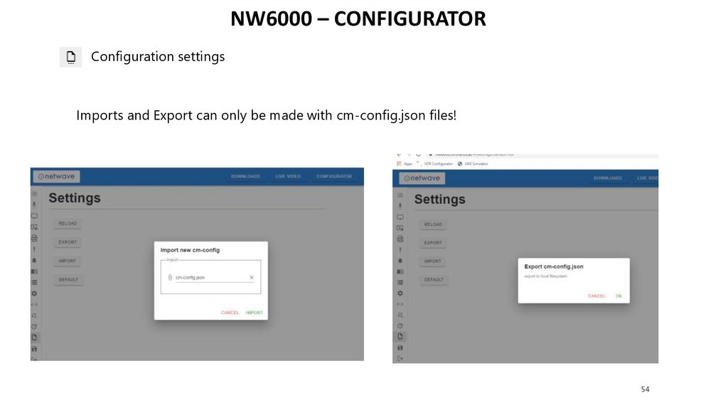
NW6000 – CONFIGURATORConfiguration settings
Imports and Export can only be made with cm-config.json files!
54
55.
NW6000 – CONFIGURATORSAVE = Save settings to the VDR.
After updating the VDR will reboot.
Select exit afterwards, and the VDR is configured
55
56.
NW6000 – CONFIGURATORREPLACING DEVICES
A new device needs to be updated before it can be probed!
Replace the broken device.
Open the configurator, and open the upgrade page
Select the last released service package and UPLOAD.
Update the new installed device
Probe & scan
Drag the new found device
to the left side & save
Video: Replacing Devices
56
57.
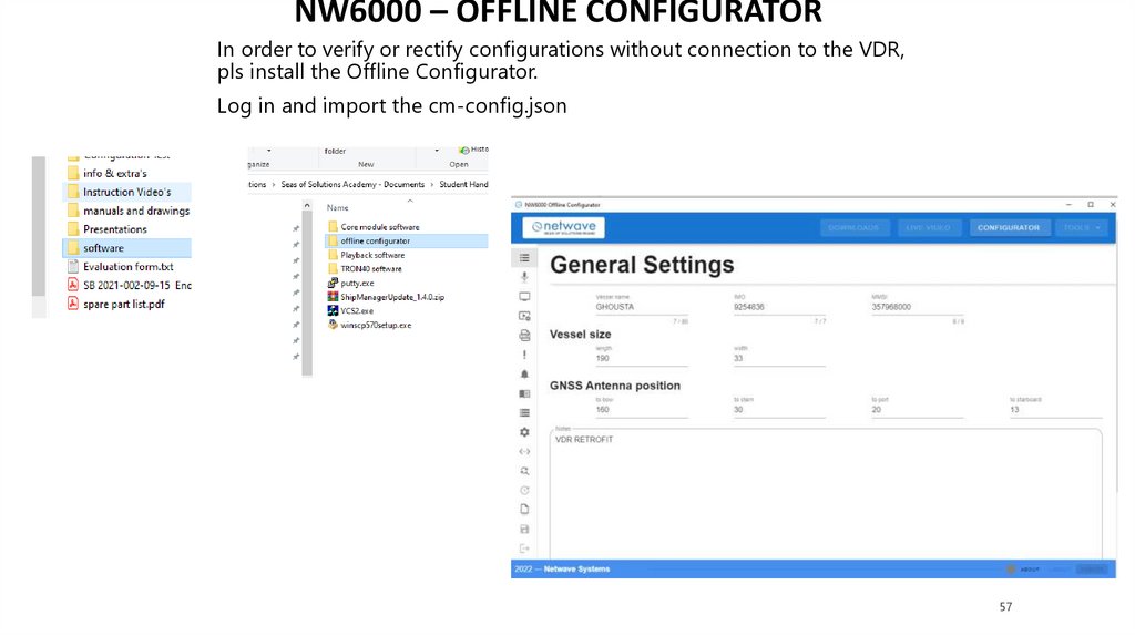
NW6000 – OFFLINE CONFIGURATORIn order to verify or rectify configurations without connection to the VDR,
pls install the Offline Configurator.
Log in and import the cm-config.json
57
58.
NW6000 – CONFIGURATOREXAMS
PRACTICAL EXAM:
Open the folder configuration test
Log in to the training room VDR and set up the configuration for the
Arklow Beach (TeamViewer required) in the VDR from the classroom, use
the camera installed to see results on BCU.
Log in access will be handed out during course
Since 3-4 people are connected, discuss with your colleagues a free time
window for everyone
Theoretical test to make:
MAKE TEST 1 AND SUBMIT
58