

 Электроника
 Военное дело
Похожие презентации:


ZARD K12 Anti-drone radar. Installation Instruction and Equipment Setup
1.
80 Installation Instruction2.
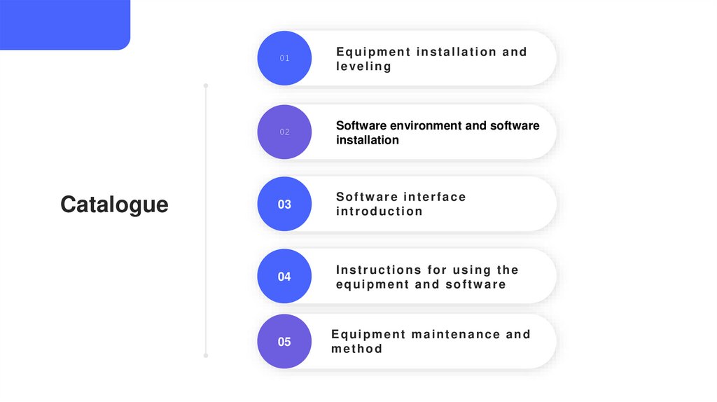
Catalogue01
Equipment installation and
leveling
02
Software environment and software
installation
03
Software interface
introduction
04
Instructions for using the
equipment and software
05
Equipment maintenance and
method
3.
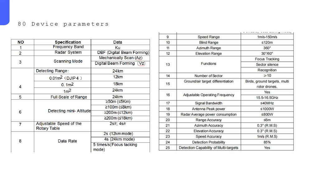
80 Device parameters4.
01Equipment installation
and leveling
5.
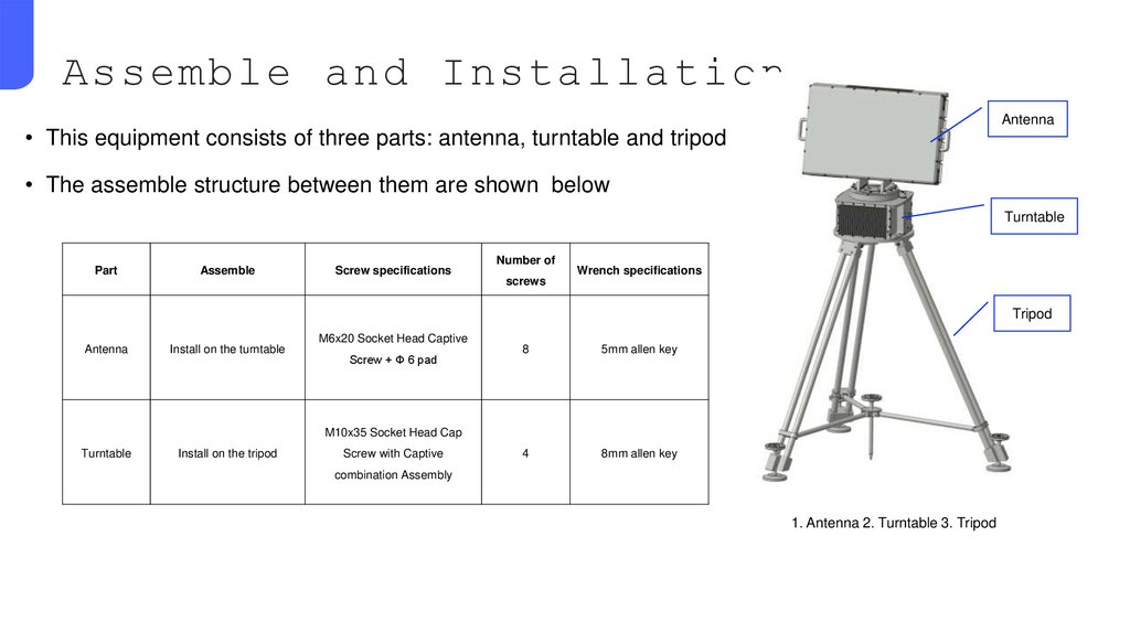
Assemble and InstallationAntenna
• This equipment consists of three parts: antenna, turntable and tripod
• The assemble structure between them are shown below
Turntable
Part
Assemble
Screw specifications
Number of
screws
Wrench specifications
Tripod
Antenna
Install on the turntable
M6x20 Socket Head Captive
Screw + Φ 6 pad
8
5mm allen key
4
8mm allen key
M10x35 Socket Head Cap
Turntable
Install on the tripod
Screw with Captive
combination Assembly
1. Antenna 2. Turntable 3. Tripod
6.
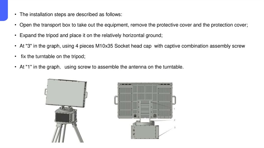
• The installation steps are described as follows:• Open the transport box to take out the equipment, remove the protective cover and the protection cover;
• Expand the tripod and place it on the relatively horizontal ground;
• At "3" in the graph, using 4 pieces M10x35 Socket head cap with captive combination assembly screw
• fix the turntable on the tripod;
• At "1" in the graph using screw to assemble the antenna on the turntable.
7.
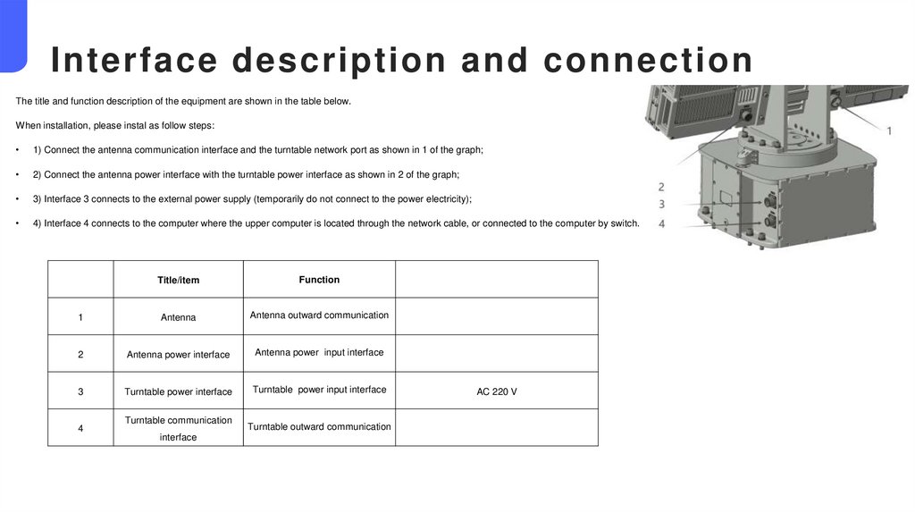
Interface description and connectionThe title and function description of the equipment are shown in the table below.
When installation, please instal as follow steps:
1) Connect the antenna communication interface and the turntable network port as shown in 1 of the graph;
2) Connect the antenna power interface with the turntable power interface as shown in 2 of the graph;
3) Interface 3 connects to the external power supply (temporarily do not connect to the power electricity);
4) Interface 4 connects to the computer where the upper computer is located through the network cable, or connected to the computer by switch.
Title/item
Function
1
Antenna
Antenna outward communication
2
Antenna power interface
Antenna power input interface
3
Turntable power interface
Turntable power input interface
4
Turntable communication
interface
Turntable outward communication
AC 220 V
8.
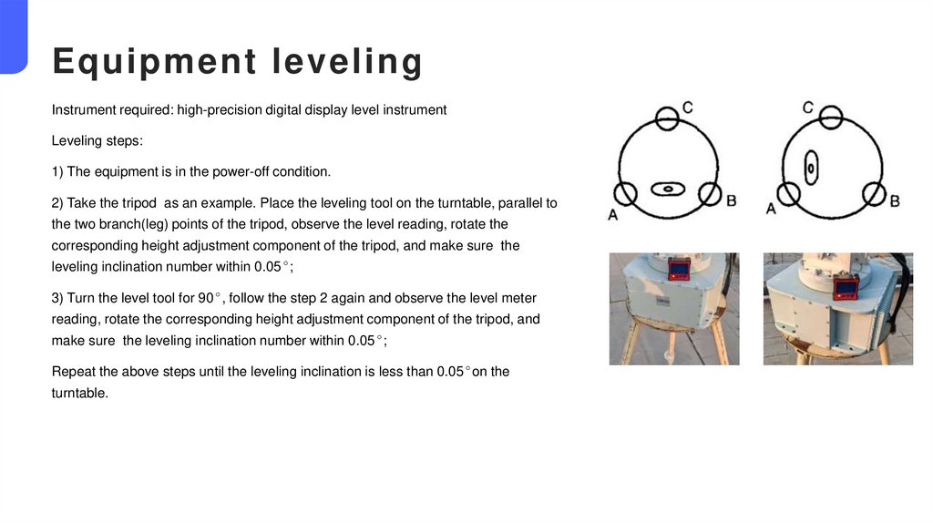
Equipment levelingInstrument required: high-precision digital display level instrument
Leveling steps:
1) The equipment is in the power-off condition.
2) Take the tripod as an example. Place the leveling tool on the turntable, parallel to
the two branch(leg) points of the tripod, observe the level reading, rotate the
corresponding height adjustment component of the tripod, and make sure the
leveling inclination number within 0.05°;
3) Turn the level tool for 90°, follow the step 2 again and observe the level meter
reading, rotate the corresponding height adjustment component of the tripod, and
make sure the leveling inclination number within 0.05°;
Repeat the above steps until the leveling inclination is less than 0.05°on the
turntable.
9.
02The software environment
and the software interface
10.
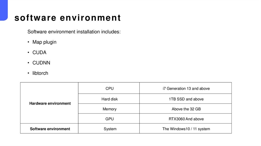
software environmentSoftware environment installation includes:
• Map plugin
• CUDA
• CUDNN
• libtorch
CPU
i7 Generation 13 and above
Hard disk
1TB SSD and above
Memory
Above the 32 GB
GPU
RTX3060 And above
System
The Windows10 / 11 system
Hardware environment
Software environment
11.
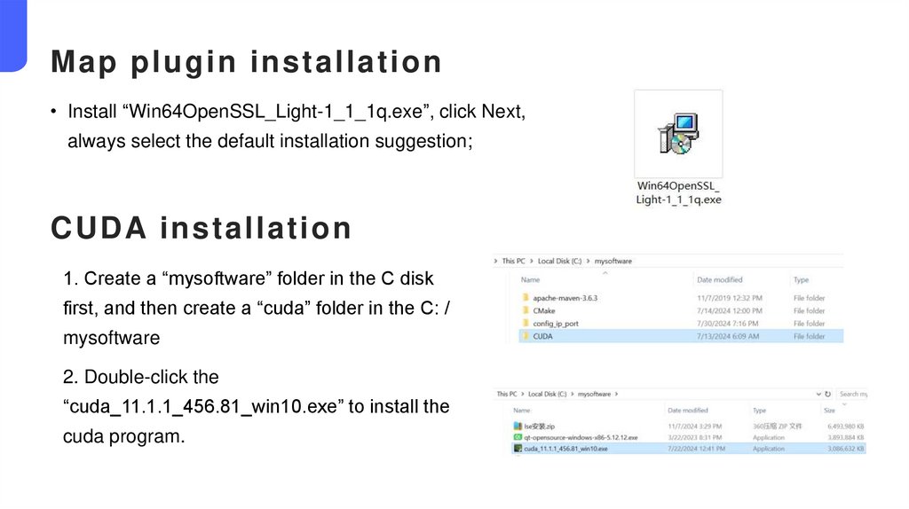
Map plugin installation• Install “Win64OpenSSL_Light-1_1_1q.exe”, click Next,
always select the default installation suggestion;
CUDA installation
1. Create a “mysoftware” folder in the C disk
first, and then create a “cuda” folder in the C: /
mysoftware
2. Double-click the
“cuda_11.1.1_456.81_win10.exe” to install the
cuda program.
12.
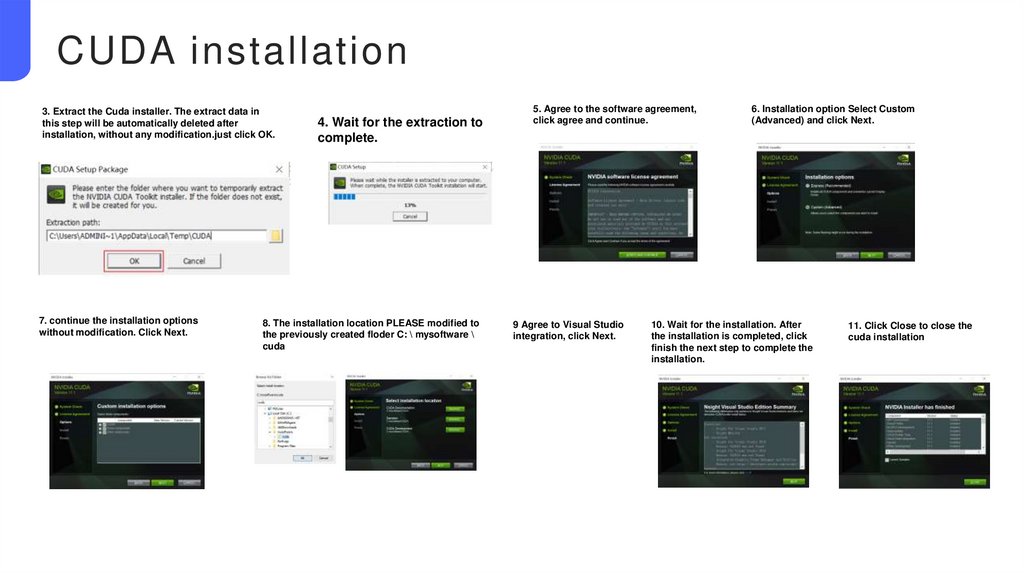
CUDA installation3. Extract the Cuda installer. The extract data in
this step will be automatically deleted after
installation, without any modification.just click OK.
7. continue the installation options
without modification. Click Next.
4. Wait for the extraction to
complete.
8. The installation location PLEASE modified to
the previously created floder C: \ mysoftware \
cuda
5. Agree to the software agreement,
click agree and continue.
9 Agree to Visual Studio
integration, click Next.
6. Installation option Select Custom
(Advanced) and click Next.
10. Wait for the installation. After
the installation is completed, click
finish the next step to complete the
installation.
11. Click Close to close the
cuda installation
13.
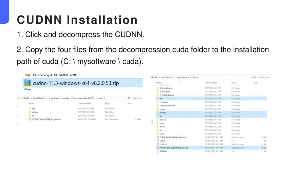
CUDNN Installation1. Click and decompress the CUDNN.
2. Copy the four files from the decompression cuda folder to the installation
path of cuda (C: \ mysoftware \ cuda).
14.
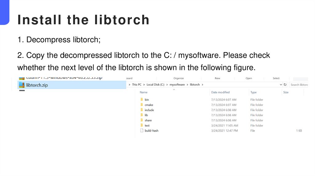
Install the libtorch1. Decompress libtorch;
2. Copy the decompressed libtorch to the C: / mysoftware. Please check
whether the next level of the libtorch is shown in the following figure.
15.
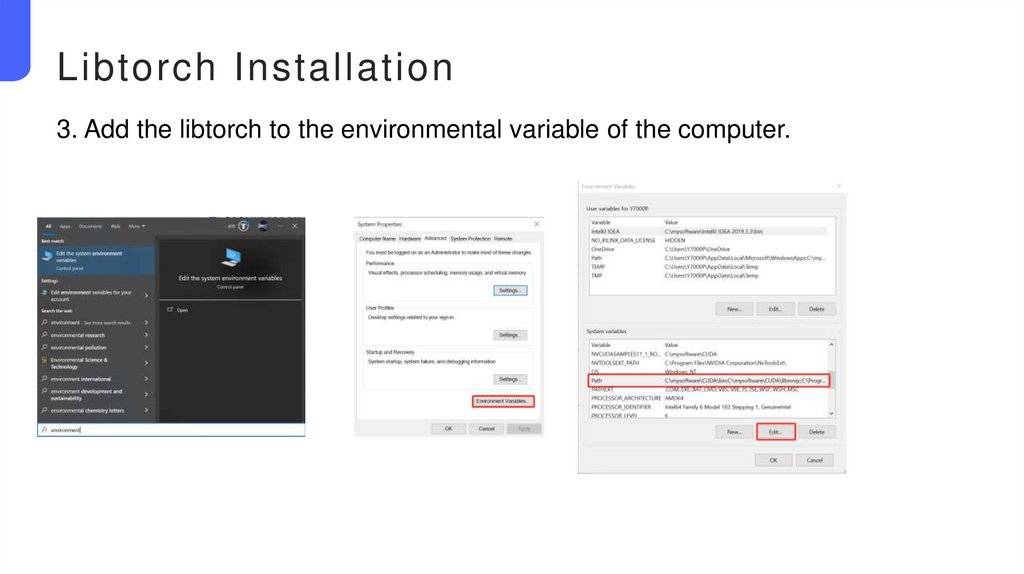
Libtorch Installation3. Add the libtorch to the environmental variable of the computer.
16.
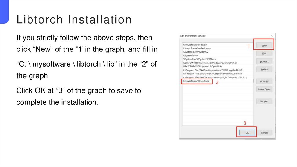
Libtorch InstallationIf you strictly follow the above steps, then
click “New” of the “1”in the graph, and fill in
“C: \ mysoftware \ libtorch \ lib” in the “2” of
the graph
Click OK at “3” of the graph to save to
complete the installation.
17.
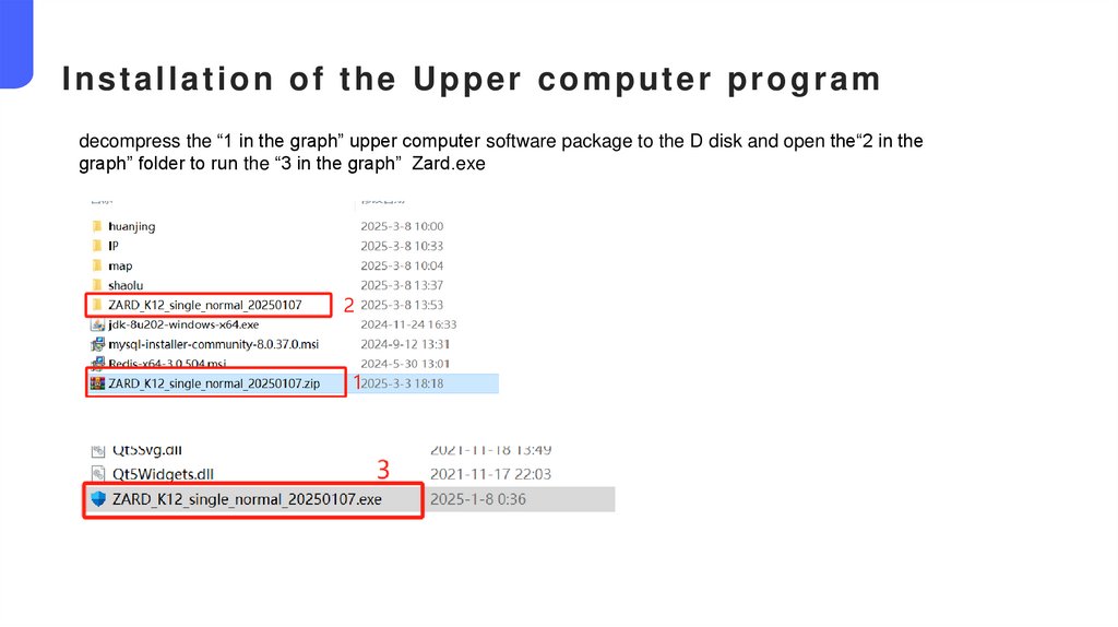
Installation of the Upper computer programdecompress the “1 in the graph” upper computer software package to the D disk and open the“2 in the
graph” folder to run the “3 in the graph” Zard.exe
18.
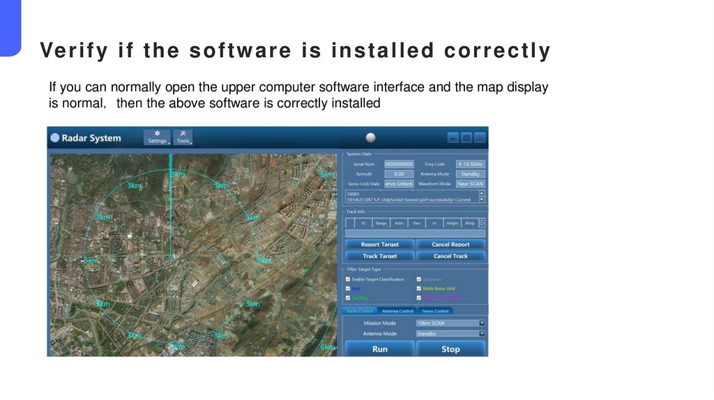
Ve r i f y i f t h e s o f t w a r e i s i n s t a l l e d c o r r e c t l yIf you can normally open the upper computer software interface and the map display
is normal then the above software is correctly installed
19.
03Software
Interface
Introduction
20.
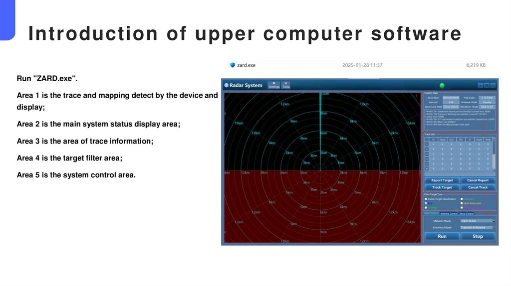
Introduction of upper computer softwareRun "ZARD.exe".
Area 1 is the trace and mapping detect by the device and
display;
Area 2 is the main system status display area;
Area 3 is the area of trace information;
Area 4 is the target filter area;
Area 5 is the system control area.
21.
Area 1Item
Definition
Time
Present time
No
The batch number of the trace
Mode
The waveform pattern corresponding to the flight tracc
Range
The distance between the target and the device
connection
Azim
Azimuth of the current dot of the trace
Elev
The pitch angle of the current dot of the trace
Vr
Radial velocity, measured in m / s
Speed
Target speed in the space, in m / s
Height
The height of the target relative to the device
Amp
The amplitude of the target echo obtained after signal
processing
SNR
The signal-to-noise ratio of the target echo obtained after
signal processing
RCS
The radar cross-sectional area of the target echo
Heading
Current heading angle of the target
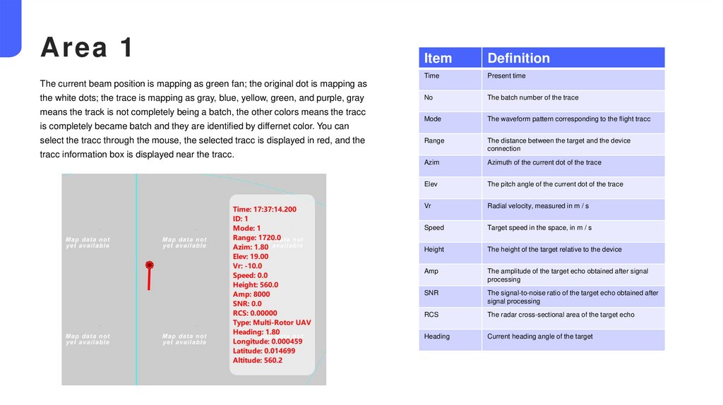
The current beam position is mapping as green fan; the original dot is mapping as
the white dots; the trace is mapping as gray, blue, yellow, green, and purple, gray
means the track is not completely being a batch, the other colors means the tracc
is completely became batch and they are identified by differnet color. You can
select the tracc through the mouse, the selected tracc is displayed in red, and the
tracc information box is displayed near the tracc.
22.
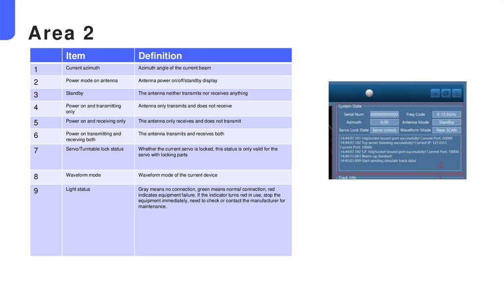
Area 2Item
Definition
1
Current azimuth
Azimuth angle of the current beam
2
Power mode on antenna
Antenna power on/off/standby display
3
Standby
The antenna neither transmits nor receives anything
4
Power on and transmitting
only
Antenna only transmits and does not receive
5
Power on and receiving only
The antenna only receives and does not transmit
6
Power on transmitting and
receiving both
The antenna transmits and receives both
7
Servo/Turntable lock status
Whether the current servo is locked, this status is only valid for the
servo with locking parts
8
Waveform mode
Waveform mode of the current device
9
Light status
Gray means no connection, green means normal connection, red
indicates equipment failure. If the indicator turns red in use, stop the
equipment immediately, need to check or contact the manufacturer for
maintenance.
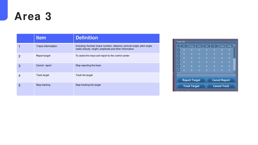
23.
Area 3Item
Definition
1
Trace information
Including: Number (trace number), distance, azimuth angle, pitch angle,
radial velocity, height, amplitude and other information
2
Report target
To select the trace and report to the control center
3
Cancel report
Stop reporting the trace
4
Track target
Track the target
5
Stop tracking
Stop tracking the target
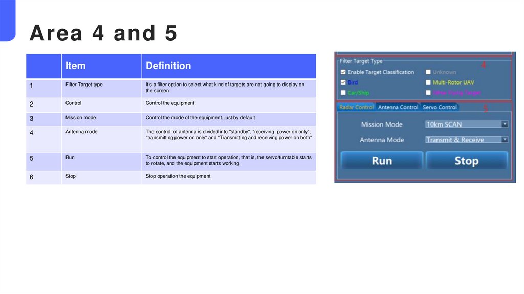
24.
Area 4 and 5Item
Definition
1
Filter Target type
It's a filter option to select what kind of targets are not going to display on
the screen
2
Control
Control the equipment
3
Mission mode
Control the mode of the equipment, just by default
4
Antenna mode
The control of antenna is divided into "standby", "receiving power on only",
"transmitting power on only" and "Transmitting and receiving power on both"
5
Run
To control the equipment to start operation, that is, the servo/turntable starts
to rotate, and the equipment starts working
6
Stop
Stop operation the equipment
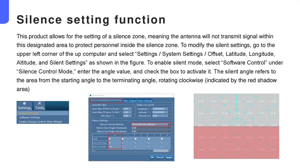
25.
Silence setting functionThis product allows for the setting of a silence zone, meaning the antenna will not transmit signal within
this designated area to protect personnel inside the silence zone. To modify the silent settings, go to the
upper left corner of the up computer and select “Settings / System Settings / Offset, Latitude, Longitude,
Altitude, and Silent Settings” as shown in the figure. To enable silent mode, select “Software Control” under
“Silence Control Mode,” enter the angle value, and check the box to activate it. The silent angle refers to
the area from the starting angle to the terminating angle, rotating clockwise (indicated by the red shadow
area)
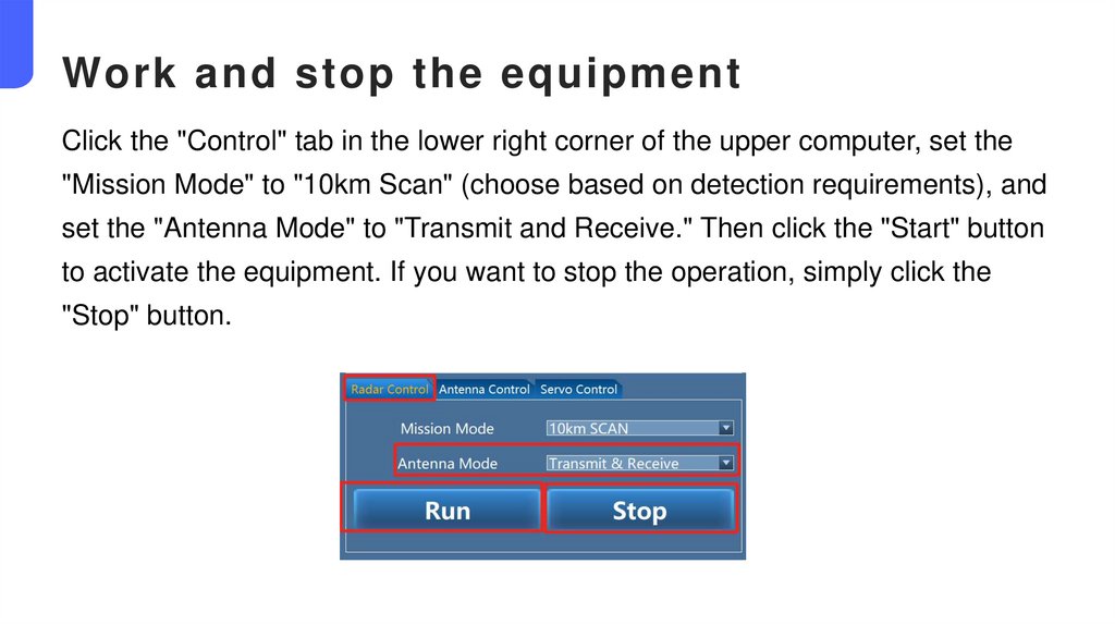
26.
Work and stop the equipmentClick the "Control" tab in the lower right corner of the upper computer, set the
"Mission Mode" to "10km Scan" (choose based on detection requirements), and
set the "Antenna Mode" to "Transmit and Receive." Then click the "Start" button
to activate the equipment. If you want to stop the operation, simply click the
"Stop" button.
27.
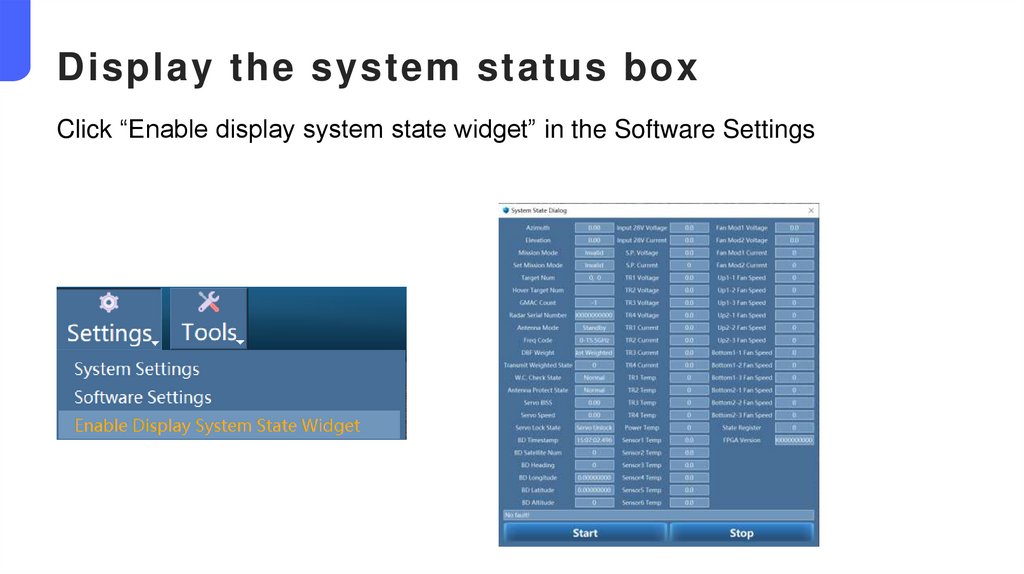
Display the system status boxClick “Enable display system state widget” in the Software Settings
28.
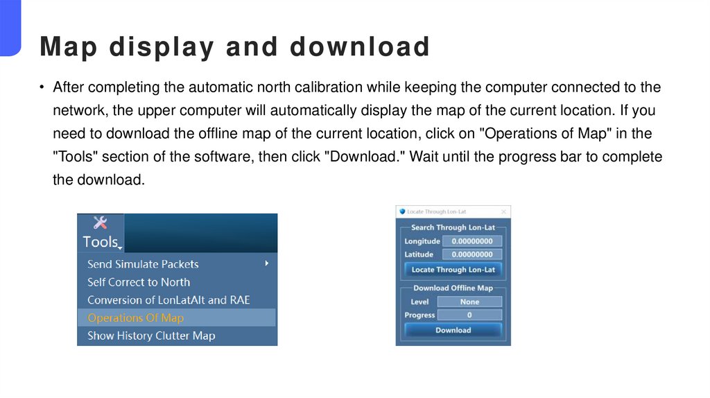
Map display and download• After completing the automatic north calibration while keeping the computer connected to the
network, the upper computer will automatically display the map of the current location. If you
need to download the offline map of the current location, click on "Operations of Map" in the
"Tools" section of the software, then click "Download." Wait until the progress bar to complete
the download.
29.
04In s t r uc tio n s o f e q u ip me nt a n d s o f tw ar e
30.
Equipment and software operation process1. Complete all the operations in chapter 1-2, the equipment has been installed, the software has been
installed, and the power supply is normal;
2. Fill in the IP address of the control computer correctly;
3. Open the upper computer software and check whether the device IP is correct. If the light in the upper
right corner of the main interface is green, indicating that the device is connected normally;
4. North finding (for the first time operation after the installation of the new position, it is recommended that
the north finding process be 2-3 times are more accurate), and remove the Beidou antenna after the
completion of the North finding process;
5. Select the working mode-transmit and receive both, and click the work;
6. Select the target to verify whether the equipment can accurately identify and track the target. When the
suspected target trace appears on the map, select the track, compare and verify the height, distance, rate,
identification type and other information with the remote control interface information of the target;
31.
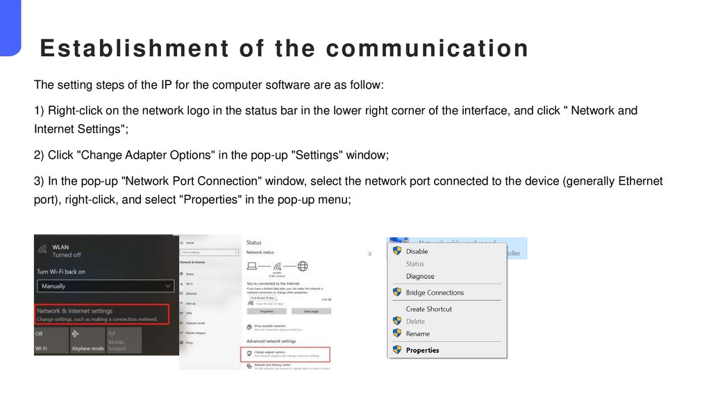
Establishment of the communicationThe setting steps of the IP for the computer software are as follow:
1) Right-click on the network logo in the status bar in the lower right corner of the interface, and click " Network and
Internet Settings";
2) Click "Change Adapter Options" in the pop-up "Settings" window;
3) In the pop-up "Network Port Connection" window, select the network port connected to the device (generally Ethernet
port), right-click, and select "Properties" in the pop-up menu;
32.
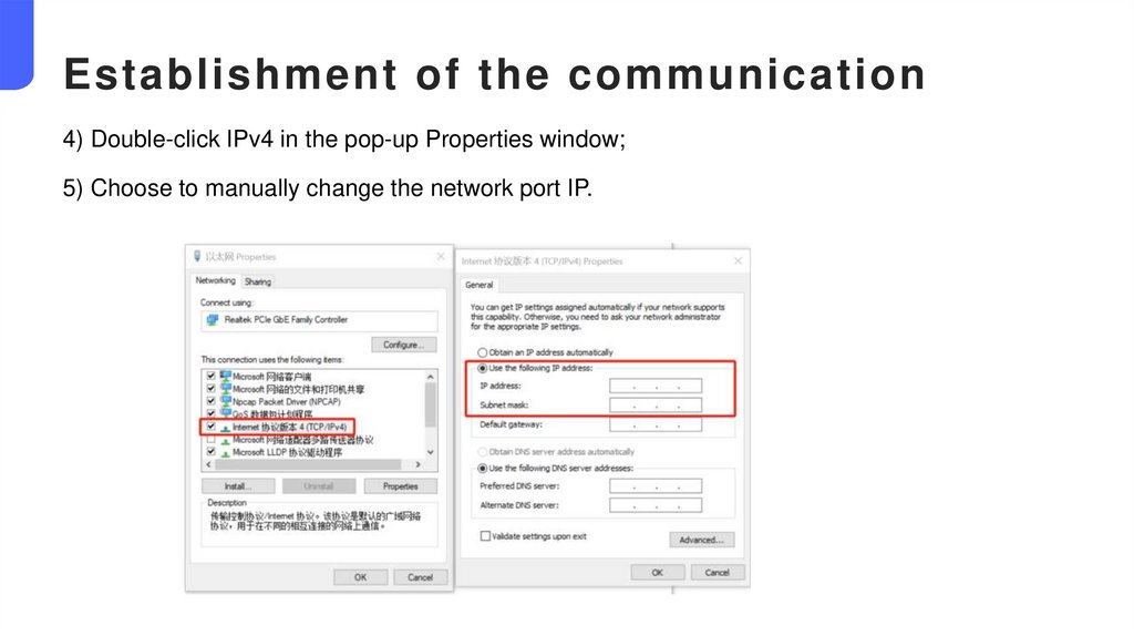
Establishment of the communication4) Double-click IPv4 in the pop-up Properties window;
5) Choose to manually change the network port IP.
33.
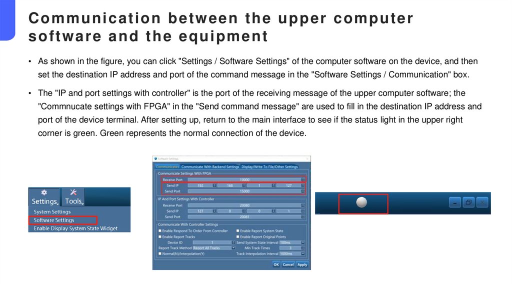
Communication between the upper computersoftware and the equipment
• As shown in the figure, you can click "Settings / Software Settings" of the computer software on the device, and then
set the destination IP address and port of the command message in the "Software Settings / Communication" box.
• The "IP and port settings with controller" is the port of the receiving message of the upper computer software; the
"Commnucate settings with FPGA" in the "Send command message" are used to fill in the destination IP address and
port of the device terminal. After setting up, return to the main interface to see if the status light in the upper right
corner is green. Green represents the normal connection of the device.
34.
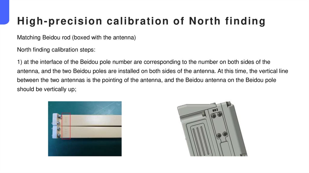
High-precision calibration of North findingMatching Beidou rod (boxed with the antenna)
North finding calibration steps:
1) at the interface of the Beidou pole number are corresponding to the number on both sides of the
antenna, and the two Beidou poles are installed on both sides of the antenna. At this time, the vertical line
between the two antennas is the pointing of the antenna, and the Beidou antenna on the Beidou pole
should be vertically up;
35.
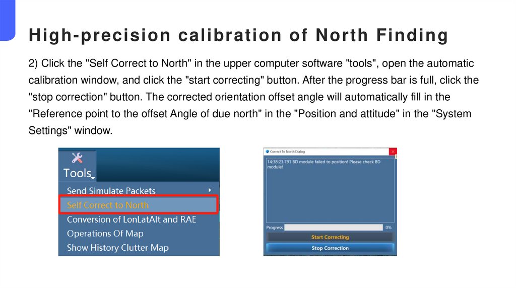
High-precision calibration of North Finding2) Click the "Self Correct to North" in the upper computer software "tools", open the automatic
calibration window, and click the "start correcting" button. After the progress bar is full, click the
"stop correction" button. The corrected orientation offset angle will automatically fill in the
"Reference point to the offset Angle of due north" in the "Position and attitude" in the "System
Settings" window.
36.
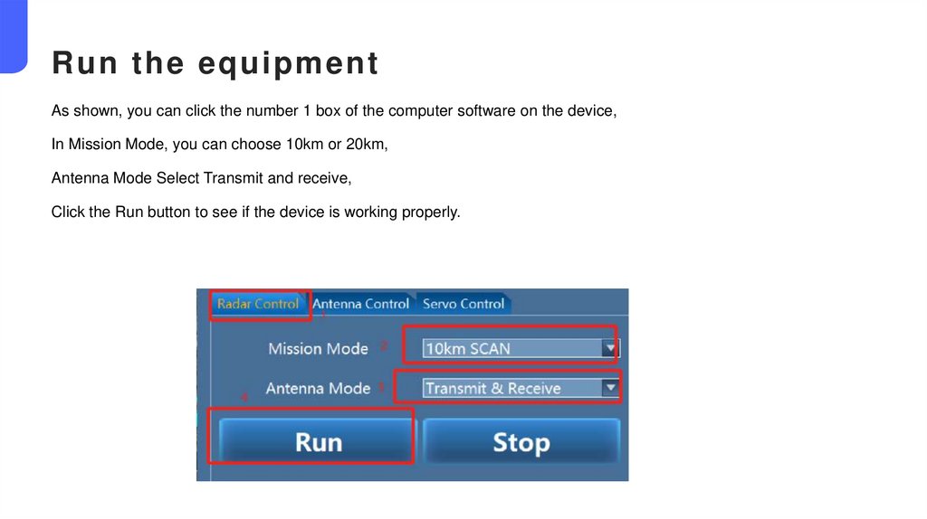
Run the equipmentAs shown, you can click the number 1 box of the computer software on the device,
In Mission Mode, you can choose 10km or 20km,
Antenna Mode Select Transmit and receive,
Click the Run button to see if the device is working properly.
37.
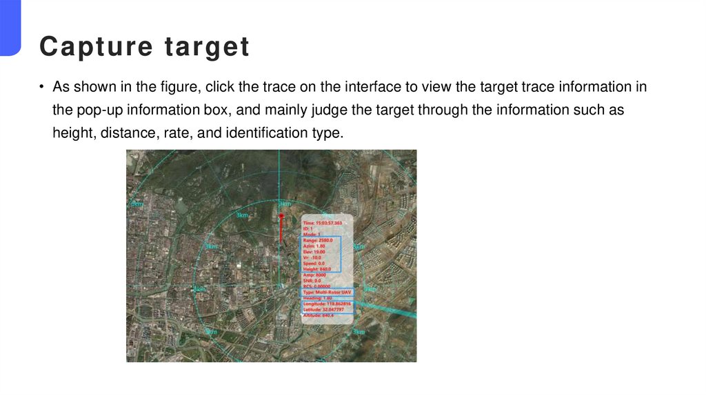
Capture target• As shown in the figure, click the trace on the interface to view the target trace information in
the pop-up information box, and mainly judge the target through the information such as
height, distance, rate, and identification type.
38.
04Equipment maintenance
and maintenance method
39.
Maintenance project instructions• The appearance maintenance
• Fan and air duct maintenance
• Waterproof air transmission valve
maintenance
• Turntable maintenance.
40.
Appearance maintenance● Appearance maintenance is mainly based on the appearance of the equipment, and the
contents of appearance maintenance are as follows:
1) Clean dust and stains on the equipment surface
● The surface conditions of the turntable, such as dust and stains need to be cleaned. Please
use clean tower for cleaning, it is strictly prohibited to use alcohol or substances containing
corrosive materials to clean.
2) Inspection of the antenna cover
● The cover is a composite material with wave transmission function, and its mechanical strength
is weaker than metal, so it is necessary to regularl y check whether the cover has cracks or
damage. Any exception requires the repair or replacement of the cover/radome.
3) Inspection of equipment cables and aviation plugs
● Check the cables and plugs of the antenna and turntable, check any cracks and damaged
insulation materials , loosening and rust of the external cables and the air plug; recommend
appearance maintenance cycle once a month.
41.
Maintenance of the fan and the air duct● This antenna adopts air cooling, with two independent air duct and four independent
fan modules, two air in fan modules and two air out fan modules.
● The air duct is separated from the interior of the antenna, that is, the external water
and air cannot enter the antenna through the air duct. Check the fan module and air
duct regularly for the dust. You can use a high pressure air gun to blow away dust, or
you can also use clean water for cleaning.
● The maintenance cycle of the fan and air duct is recommended once a month.
42.
Maintenance of the waterproof air transmission valve● The waterproof transmission valve is located at the bottom of the antenna. In order to
prevent the waterproof transmission valve from being blocked by dust, the waterproof
transmission valve needs to be checked and cleaned. You can use clean water to keep
it clean.The maintenance cycle of the waterproof vent valve is recommended once a
month.
Tu r n t a b l e m a i n t e n a n c e
● Whether there are dust blockage at the gap of the rotating plate of the turntable. If
there is sand dust blockage, it needs to be cleaned in time to avoid abnormal rotation
of the turntable.At sand dust or harsh environment, it is recommended to check it
weekly.
Tr i p o d m a i n t e n a n c e
● Check the screws for loosening regularly.
43.
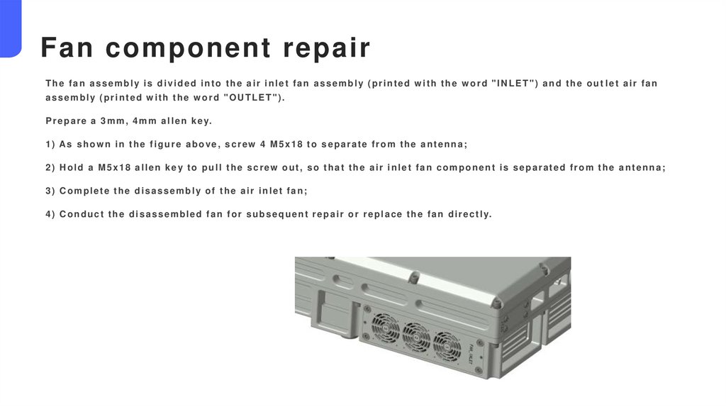
Fan component repairThe fan assembly is divided into the air inlet fan assembly (printed w ith the w ord "INLET") and the out let air fan
assembly (printed with the word "OUTLET").
P r e p a r e a 3 m m , 4 m m a l l e n k e y.
1 ) As s h o w n i n t h e f i g u r e a b o v e , s c r e w 4 M 5 x 1 8 t o s e p a r a t e f r o m t h e a n t e n n a ;
2) Hold a M5x18 allen key to pull the screw out, so that the air inlet fan component is separated from the antenna;
3) Complete the disassembly of the air inlet fan;
4 ) C o n d u c t t h e d i s a s s e m b l e d f a n f o r s u b s e q u e n t r e p a i r o r r e p l a c e t h e f a n d i r e c t l y.
44.
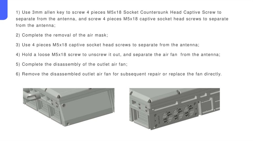
1) Use 3mm allen key to screw 4 pieces M5x18 Socket Countersunk Head Captive Screw toseparate from the antenna, and screw 4 pieces M5x18 captive socket head screws to separate
from the antenna;
2) Complete the removal of the air mask;
3) Use 4 pieces M5x18 captive socket head screws to separate from the antenna;
4) Hold a loose M5x18 screw to unscrew it out, and separate the air fan from the antenna;
5) Complete the disassembly of the outlet air fan;
6) Remove the disassembled outlet air fan for subsequent repair or replace the fan directly.