

 Электроника
Похожие презентации:


")
samsung_ww90j5456fw_eu_ww5000j_wf80f5e_ww7x_ww8x_ww9x_training_manual (1)
1.
WW5000J - PJTSAMSUNG Clothes Washer
Training Manual
Basic Model : WF80F5E
(F500E PROJECT)
Model Name : WW7*J5/WW8*J5/WW9*J5
(WW5000J PROJECT)
Model Code : WW7*J52***W/X WW7*J53***W/X
WW7*J54***W/X WW7*J55***W/X
WW8*J52***W/X WW8*J53***W/X
WW8*J54***W/X WW8*J55***W/X
WW9*J52***W/X WW9*J53***W/X
WW9*J54***W/X WW9*J55***W/X
(WW5000J PROJECT)
WW90J5456FW/EU
JANUARY 2017
-1-
Digital Appliances Division
2.
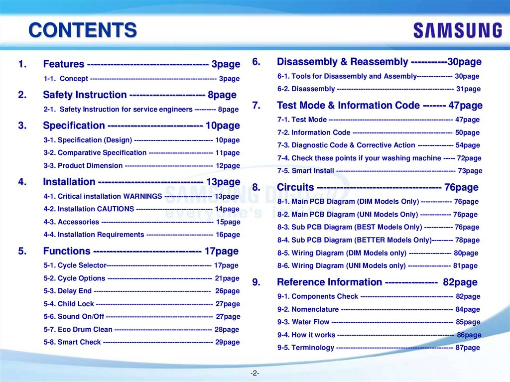
CONTENTS1.
Features ------------------------------------- 3page
6.
6-1. Tools for Disassembly and Assembly--------------- 30page
1-1. Concept ----------------------------------------------------- 3page
2.
3.
6-2. Disassembly ------------------------------------------------- 31page
Safety Instruction ----------------------- 8page
2-1. Safety Instruction for service engineers --------- 8page
7.
7-2. Information Code ------------------------------------------ 50page
7-3. Diagnostic Code & Corrective Action --------------- 54page
3-2. Comparative Specification --------------------------- 11page
7-4. Check these points if your washing machine ----- 72page
3-3. Product Dimension ------------------------------------- 12page
Installation -------------------------------- 13page
7-5. Smart Install -------------------------------------------------- 73page
8.
4-1. Critical installation WARNINGS -------------------- 13page
Circuits -------------------------------------- 76page
8-1. Main PCB Diagram (DIM Models Only) ------------- 76page
4-2. Installation CAUTIONS -------------------------------- 14page
8-2. Main PCB Diagram (UNI Models Only) ------------- 76page
4-3. Accessories ----------------------------------------------- 15page
8-3. Sub PCB Diagram (BEST Models Only) ------------ 76page
4-4. Installation Requirements ---------------------------- 16page
5.
Test Mode & Information Code ------- 47page
7-1. Test Mode ---------------------------------------------------- 47page
Specification ----------------------------- 10page
3-1. Specification (Design) --------------------------------- 10page
4.
Disassembly & Reassembly -----------30page
8-4. Sub PCB Diagram (BETTER Models Only)--------- 78page
Functions --------------------------------- 17page
8-5. Wiring Diagram (DIM Models only) ------------------ 80page
5-1. Cycle Selector-------------------------------------------- 17page
8-6. Wiring Diagram (UNI Models only) ------------------ 81page
5-2. Cycle Options -------------------------------------------- 21page
9.
5-3. Delay End ------------------------------------------------- 26page
Reference Information ---------------- 82page
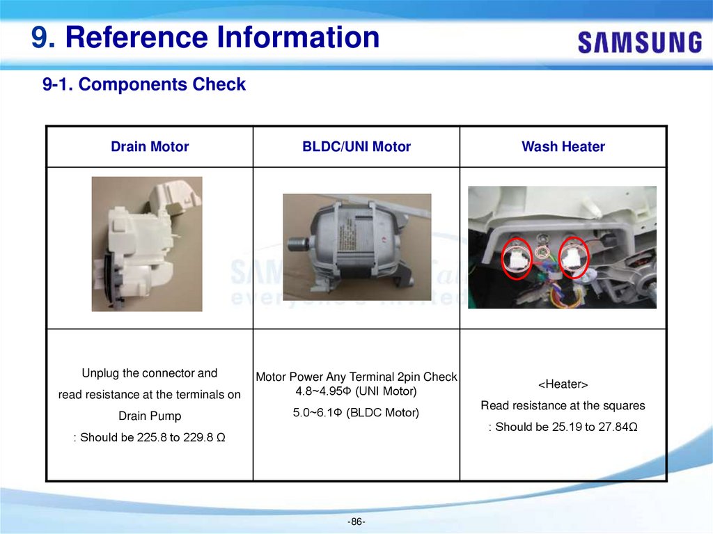
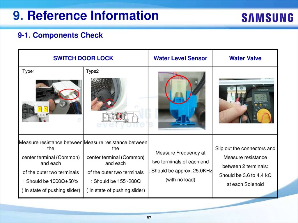
9-1. Components Check --------------------------------------- 82page
5-4. Child Lock ------------------------------------------------- 27page
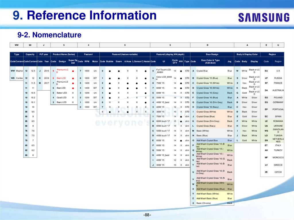
9-2. Nomenclature ----------------------------------------------- 84page
5-6. Sound On/Off --------------------------------------------- 27page
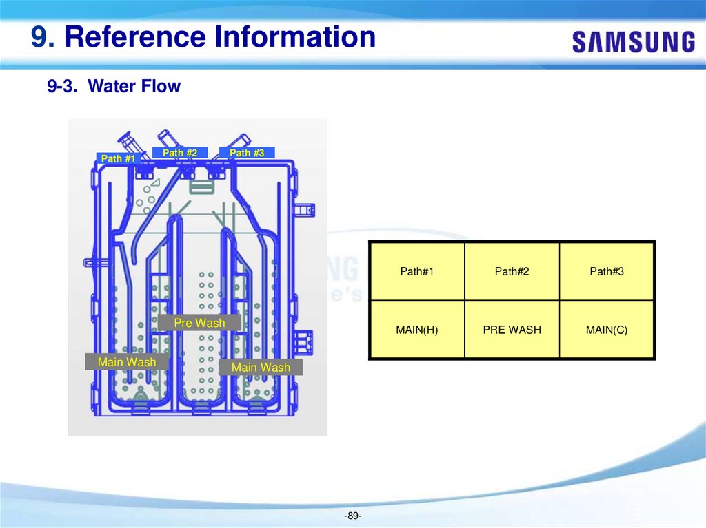
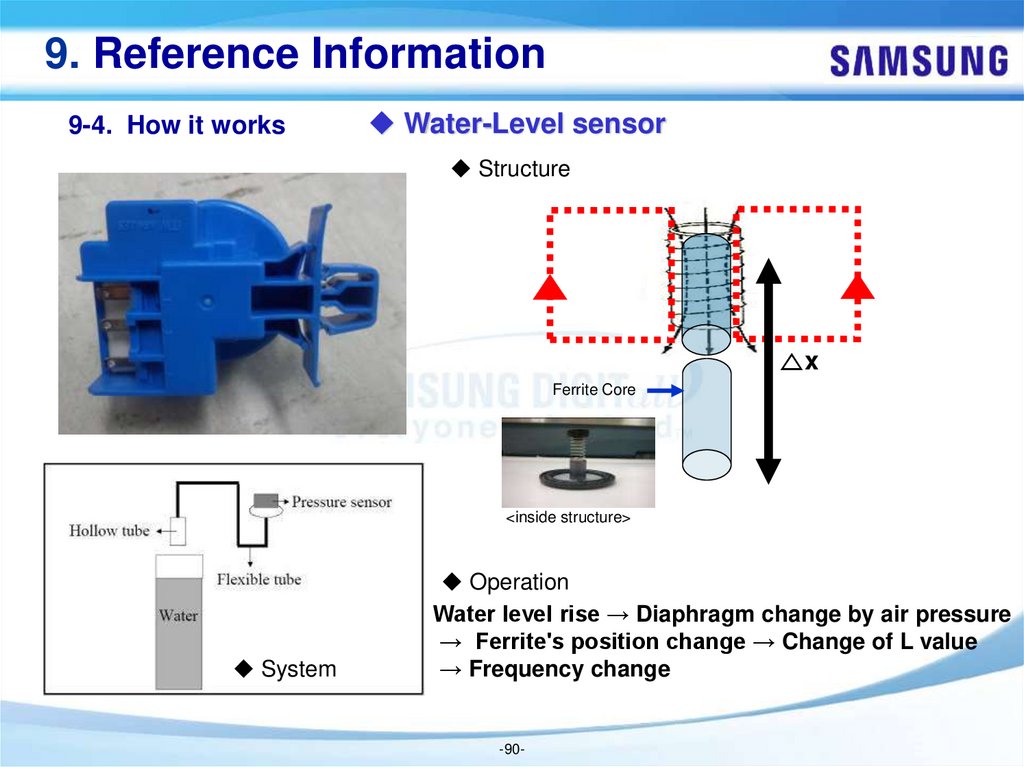
9-3. Water Flow --------------------------------------------------- 85page
5-7. Eco Drum Clean ----------------------------------------- 28page
9-4. How it works ------------------------------------------------- 86page
5-8. Smart Check ---------------------------------------------- 29page
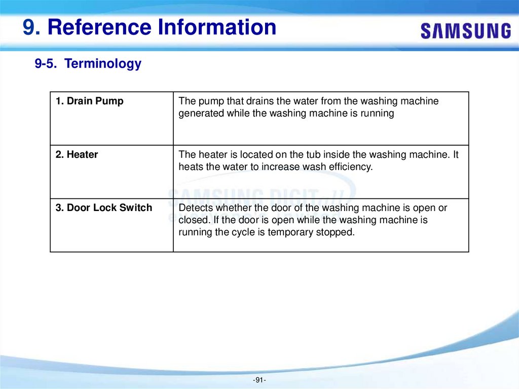
9-5. Terminology ------------------------------------------------- 87page
-2-
3.
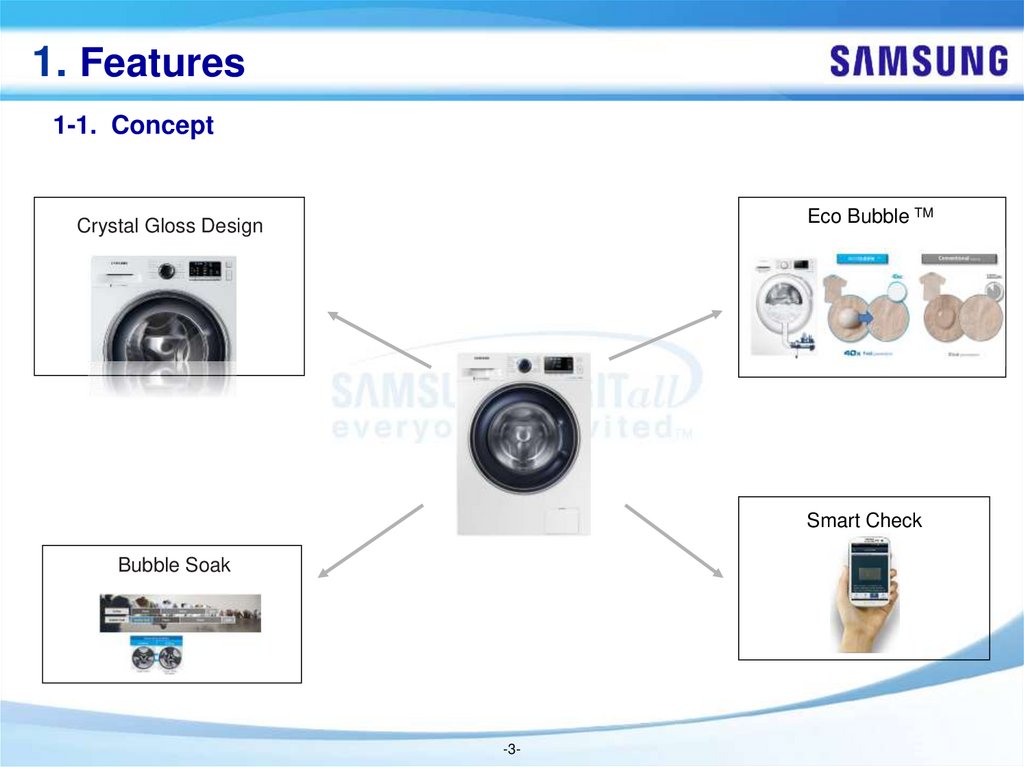
1. Features1-1. Concept
Eco Bubble TM
Crystal Gloss Design
Smart Check
Bubble Soak
-3-
4.
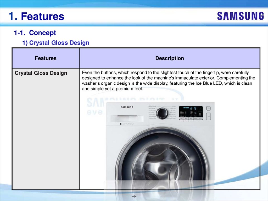
1. Features1-1. Concept
1) Crystal Gloss Design
Features
Crystal Gloss Design
Description
Even the buttons, which respond to the slightest touch of the fingertip, were carefully
designed to enhance the look of the machine's immaculate exterior. Complementing the
washer’s organic design is the wide display, featuring the Ice Blue LED, which is clean
and simple yet a premium feel.
-4-
5.
1. Features1-1. Concept
2) Smart Check
Features
Smart Check
Description
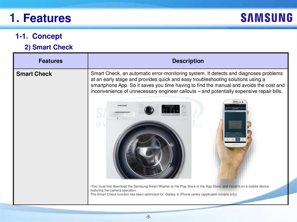
Smart Check, an automatic error-monitoring system. It detects and diagnoses problems
at an early stage and provides quick and easy troubleshooting solutions using a
smartphone App. So it saves you time having to find the manual and avoids the cost and
inconvenience of unnecessary engineer callouts – and potentially expensive repair bills.
•You must first download the Samsung Smart Washer at the Play Store or the App Store, and install it on a mobile device
featuring the camera operation.
The Smart Check function has been optimized for: Galaxy & iPhone series (applicable models only)
-5-
6.
1. Features1-1. Concept
3) Eco BubbleTM
Features
Eco BubbleTM
Description
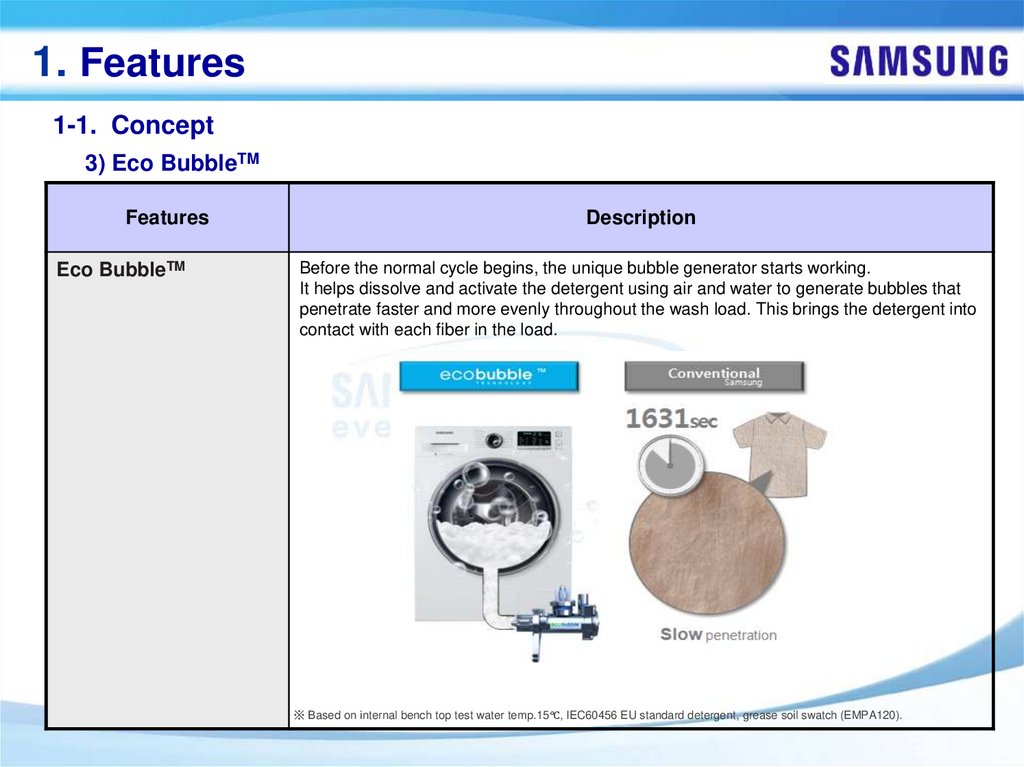
Before the normal cycle begins, the unique bubble generator starts working.
It helps dissolve and activate the detergent using air and water to generate bubbles that
penetrate faster and more evenly throughout the wash load. This brings the detergent into
contact with each fiber in the load.
※ Based on internal bench top test water temp.15℃, IEC60456 EU standard detergent, grease soil swatch (EMPA120).
7.
1. Features1-1. Concept
4) Bubble Soak
Features
Bubble Soak
Description
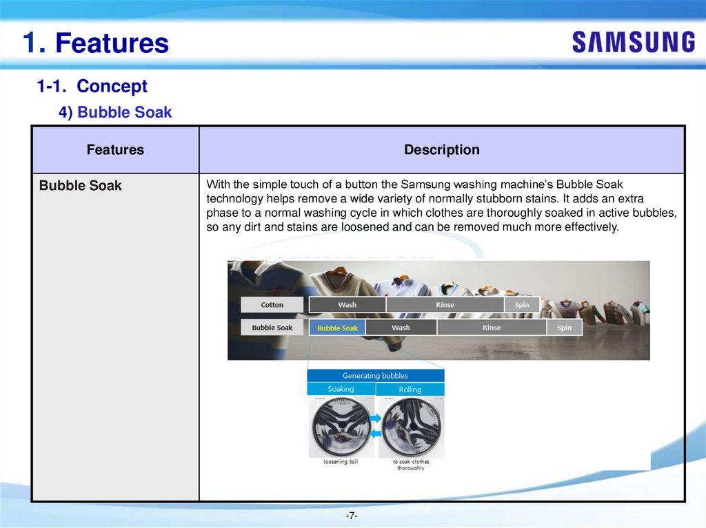
With the simple touch of a button the Samsung washing machine’s Bubble Soak
technology helps remove a wide variety of normally stubborn stains. It adds an extra
phase to a normal washing cycle in which clothes are thoroughly soaked in active bubbles,
so any dirt and stains are loosened and can be removed much more effectively.
-7-
8.
2. Safety Instruction2-1. SAFETY INSTRUCTIONS FOR SERVICE ENGINEERS
► Make sure to observe the following instructions to operate the product correctly and safely and prevent possible
accidents and hazards while servicing.
► Two types of safety symbols, Warning and Caution, are used in the safety instructions.
Hazards or unsafe practices that may result in severe personal injury or death.
Hazards or unsafe practices that may result in minor personal injury or property damage.
WARNING
BEFORE SERVICING
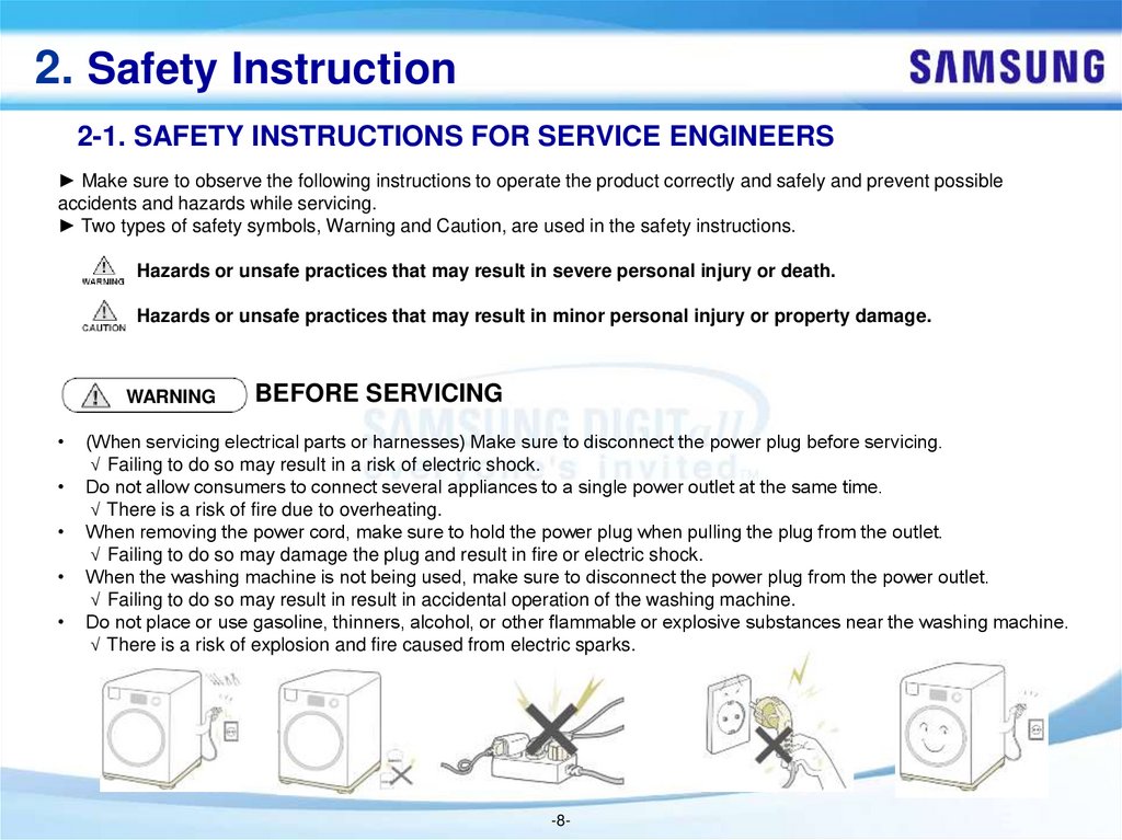
(When servicing electrical parts or harnesses) Make sure to disconnect the power plug before servicing.
√ Failing to do so may result in a risk of electric shock.
Do not allow consumers to connect several appliances to a single power outlet at the same time.
√ There is a risk of fire due to overheating.
When removing the power cord, make sure to hold the power plug when pulling the plug from the outlet.
√ Failing to do so may damage the plug and result in fire or electric shock.
When the washing machine is not being used, make sure to disconnect the power plug from the power outlet.
√ Failing to do so may result in result in accidental operation of the washing machine.
Do not place or use gasoline, thinners, alcohol, or other flammable or explosive substances near the washing machine.
√ There is a risk of explosion and fire caused from electric sparks.
-8-
9.
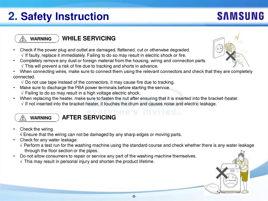
2. Safety InstructionWARNING
WHILE SERVICING
Check if the power plug and outlet are damaged, flattened, cut or otherwise degraded.
√ If faulty, replace it immediately. Failing to do so may result in electric shock or fire.
• Completely remove any dust or foreign material from the housing, wiring and connection parts.
√ This will prevent a risk of fire due to tracking and shorts in advance.
• When connecting wires, make sure to connect them using the relevant connectors and check that they are completely
connected.
√ Do not use tape instead of the connectors, it may cause fire due to tracking.
• Make sure to discharge the PBA power terminals before starting the service.
√ Failing to do so may result in a high voltage electric shock.
• When replacing the heater, make sure to fasten the nut after ensuring that it is inserted into the bracket-heater.
√ If not inserted into the bracket-heater, it touches the drum and causes noise and electric leakage.
WARNING
AFTER SERVICING
Check the wiring.
√ Ensure that the wiring can not be damaged by any sharp edges or moving parts.
Check for any water leakage.
√ Perform a test run for the washing machine using the standard course and check whether there is any water leakage
through the floor section or the pipes.
Do not allow consumers to repair or service any part of the washing machine themselves.
√ This may result in personal injury and shorten the product lifetime.
-9-
10.
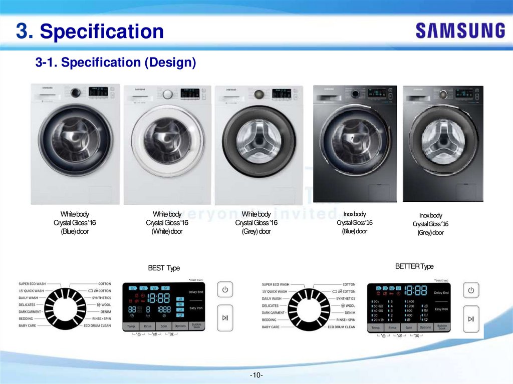
3. Specification3-1. Specification (Design)
White body
Crystal Gloss ’16
(Blue) door
White body
Crystal Gloss ’16
(White) door
White body
Crystal Gloss ’16
(Grey) door
Inoxbody
CrystalGloss’16
(Blue)door
Inoxbody
CrystalGloss’16
(Grey)door
BETTER Type
BEST Type
-10-
11.
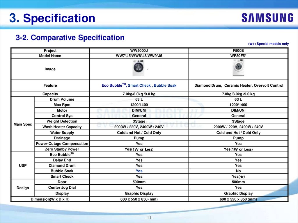
3. Specification3-2. Comparative Specification
(★) : Special models only
Project
Model Name
WW5000J
WW7*J5/WW8*J5/WW9*J5
F500E
WF80F5*
Eco BubbleTM, Smart Check , Bubble Soak
Diamond Drum, Ceramic Heater, Overvolt Control
Capacity
Drum Volume
Max Rpm
Motor
Control Sys
Weight Detection
7.0kg/8.0kg /9.0 kg
63 L
1200/1400
DIM/UNI
General
3Stage
7.0kg/8.0kg /9.0 kg
63 L
1200/1400
DIM/UNI
General
3Stage
Wash Heater Capacity
2000W / 220V, 2400W / 240V
2000W / 220V, 2400W / 240V
Water Supply
Drainage
Power-Outage Compensation
Zero Stanby Power
Eco BubbleTM
Delay End
Diamond Drum
Bubble Soak
Smart Check
Door
Center Jog Dial
Cold and Hot / Cold Only
Pump
Yes
Yes(1W or Less)
Yes
Yes
Yes
Yes
Yes
500mm
Yes
Cold and Hot / Cold Only
Pump
Yes
Yes(1W or Less)
Yes
Yes
Yes
No
Yes(★)
500mm
Yes
Display
Graphic Display
Graphic Display
600 x 550 x 850 (mm)
600 x 550 x 850 (mm)
Image
Feature
Main Spec
USP
Design
Dimension(W x D x H)
-11-
12.
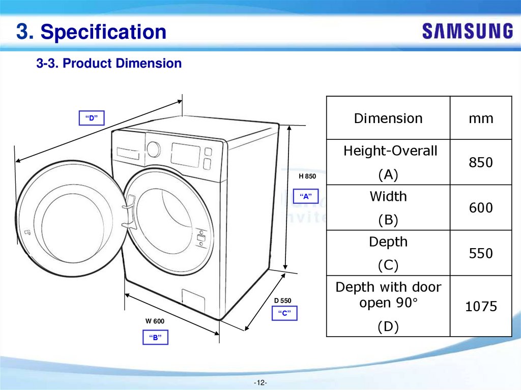
3. Specification3-3. Product Dimension
Dimension
“D”
Height-Overall
H 850
(A)
“A”
Width
(B)
Depth
(C)
D 550
“C”
Depth with door
open 90°
(D)
W 600
“B”
-12-
mm
850
600
550
1075
13.
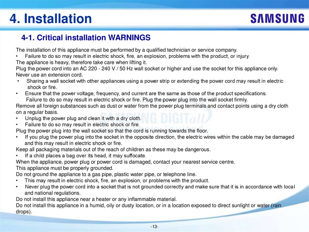
4. Installation4-1. Critical installation WARNINGS
The installation of this appliance must be performed by a qualified technician or service company.
• Failure to do so may result in electric shock, fire, an explosion, problems with the product, or injury.
The appliance is heavy, therefore take care when lifting it.
Plug the power cord into an AC 220 - 240 V / 50 Hz wall socket or higher and use the socket for this appliance only.
Never use an extension cord.
• Sharing a wall socket with other appliances using a power strip or extending the power cord may result in electric
shock or fire.
• Ensure that the power voltage, frequency, and current are the same as those of the product specifications.
Failure to do so may result in electric shock or fire. Plug the power plug into the wall socket firmly.
Remove all foreign substances such as dust or water from the power plug terminals and contact points using a dry cloth
on a regular basis.
• Unplug the power plug and clean it with a dry cloth.
• Failure to do so may result in electric shock or fire.
Plug the power plug into the wall socket so that the cord is running towards the floor.
• If you plug the power plug into the socket in the opposite direction, the electric wires within the cable may be damaged
and this may result in electric shock or fire.
Keep all packaging materials out of the reach of children as these may be dangerous.
• If a child places a bag over its head, it may suffocate.
When the appliance, power plug or power cord is damaged, contact your nearest service centre.
This appliance must be properly grounded.
Do not ground the appliance to a gas pipe, plastic water pipe, or telephone line.
• This may result in electric shock, fire, an explosion, or problems with the product.
• Never plug the power cord into a socket that is not grounded correctly and make sure that it is in accordance with local
and national regulations.
Do not install this appliance near a heater or any inflammable material.
Do not install this appliance in a humid, oily or dusty location, or in a location exposed to direct sunlight or water (rain
drops).
-13-
14.
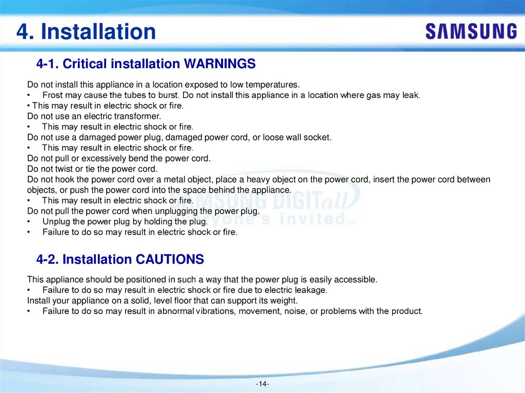
4. Installation4-1. Critical installation WARNINGS
Do not install this appliance in a location exposed to low temperatures.
• Frost may cause the tubes to burst. Do not install this appliance in a location where gas may leak.
• This may result in electric shock or fire.
Do not use an electric transformer.
• This may result in electric shock or fire.
Do not use a damaged power plug, damaged power cord, or loose wall socket.
• This may result in electric shock or fire.
Do not pull or excessively bend the power cord.
Do not twist or tie the power cord.
Do not hook the power cord over a metal object, place a heavy object on the power cord, insert the power cord between
objects, or push the power cord into the space behind the appliance.
• This may result in electric shock or fire.
Do not pull the power cord when unplugging the power plug.
• Unplug the power plug by holding the plug.
• Failure to do so may result in electric shock or fire.
4-2. Installation CAUTIONS
This appliance should be positioned in such a way that the power plug is easily accessible.
• Failure to do so may result in electric shock or fire due to electric leakage.
Install your appliance on a solid, level floor that can support its weight.
• Failure to do so may result in abnormal vibrations, movement, noise, or problems with the product.
-14-
15.
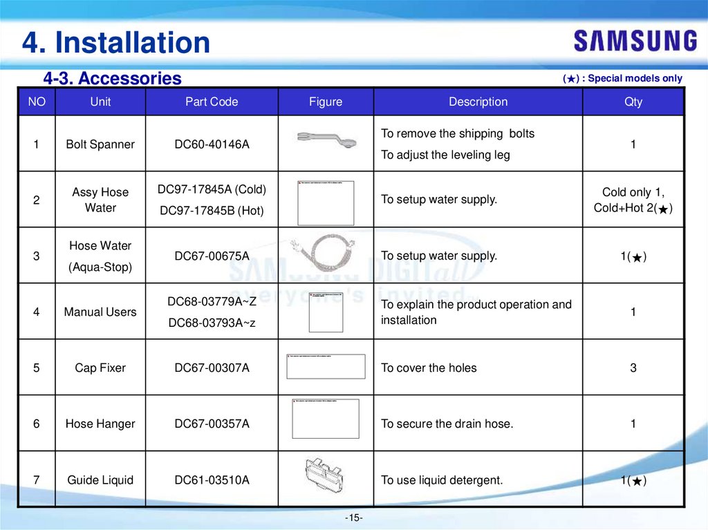
4. Installation4-3. Accessories
(★) : Special models only
NO
Unit
Part Code
1
Bolt Spanner
DC60-40146A
2
Assy Hose
Water
DC97-17845A (Cold)
3
Hose Water
(Aqua-Stop)
Figure
Description
To remove the shipping bolts
To adjust the leveling leg
Qty
1
To setup water supply.
Cold only 1,
Cold+Hot 2(★)
DC67-00675A
To setup water supply.
1(★)
DC68-03779A~Z
DC68-03793A~z
To explain the product operation and
installation
1
DC97-17845B (Hot)
4
Manual Users
5
Cap Fixer
DC67-00307A
To cover the holes
3
6
Hose Hanger
DC67-00357A
To secure the drain hose.
1
7
Guide Liquid
DC61-03510A
To use liquid detergent.
1(★)
-15-
16.
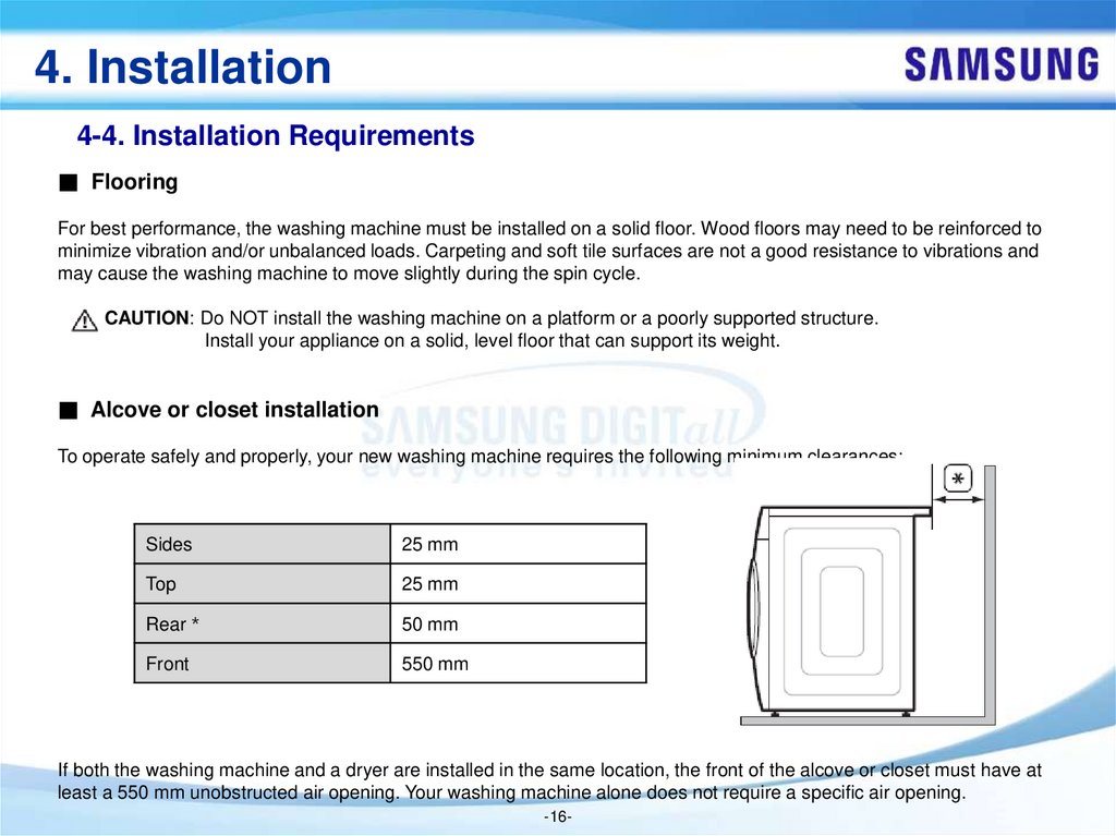
4. Installation4-4. Installation Requirements
■ Flooring
For best performance, the washing machine must be installed on a solid floor. Wood floors may need to be reinforced to
minimize vibration and/or unbalanced loads. Carpeting and soft tile surfaces are not a good resistance to vibrations and
may cause the washing machine to move slightly during the spin cycle.
CAUTION: Do NOT install the washing machine on a platform or a poorly supported structure.
Install your appliance on a solid, level floor that can support its weight.
■ Alcove or closet installation
To operate safely and properly, your new washing machine requires the following minimum clearances:
Sides
25 mm
Top
25 mm
Rear
50 mm
Front
550 mm
If both the washing machine and a dryer are installed in the same location, the front of the alcove or closet must have at
least a 550 mm unobstructed air opening. Your washing machine alone does not require a specific air opening.
-16-
17.
5. Functions5-1. Cycle Selector
WW7*J5**6**/WW8*J5**6**
WW9*J5**6**
WW7*J5**5**/WW8*J5**5**
WW9*J5**5**
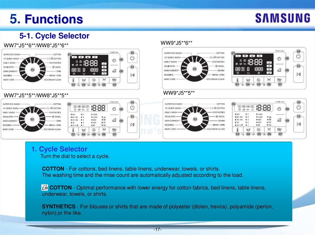
1. Cycle Selector
Turn the dial to select a cycle.
COTTON - For cottons, bed linens, table linens, underwear, towels, or shirts.
The washing time and the rinse count are automatically adjusted according to the load.
COTTON - Optimal performance with lower energy for cotton fabrics, bed linens, table linens,
underwear, towels, or shirts.
SYNTHETICS - For blouses or shirts that are made of polyester (diolen, trevira), polyamide (perlon,
nylon),or the like.
-17-
18.
5. Functions5-1. Cycle Selector
WW7*J5**6**/WW8*J5**6**
WW9*J5**6**
WW7*J5**5**/WW8*J5**5**
WW9*J5**5**
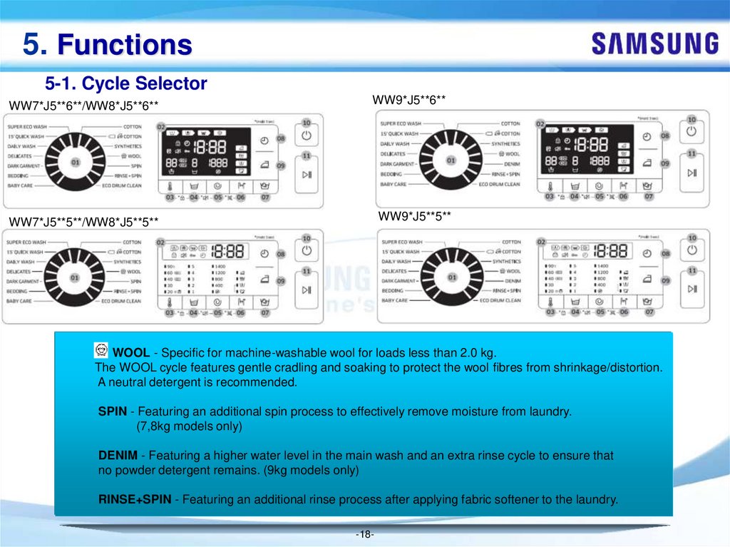
WOOL - Specific for machine-washable wool for loads less than 2.0 kg.
The WOOL cycle features gentle cradling and soaking to protect the wool fibres from shrinkage/distortion.
A neutral detergent is recommended.
SPIN - Featuring an additional spin process to effectively remove moisture from laundry.
(7,8kg models only)
DENIM - Featuring a higher water level in the main wash and an extra rinse cycle to ensure that
no powder detergent remains. (9kg models only)
RINSE+SPIN - Featuring an additional rinse process after applying fabric softener to the laundry.
-18-
19.
5. Functions5-1. Cycle Selector
WW7*J5**6**/WW8*J5**6**
WW9*J5**6**
WW7*J5**5**/WW8*J5**5**
WW9*J5**5**
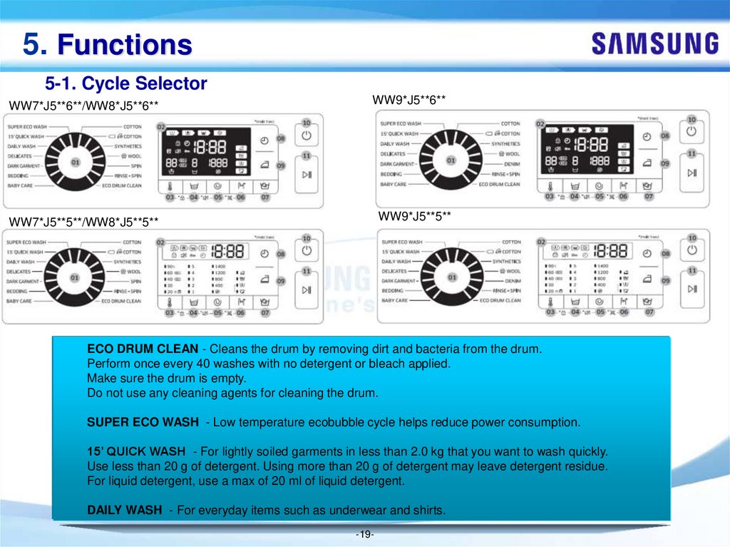
ECO DRUM CLEAN - Cleans the drum by removing dirt and bacteria from the drum.
Perform once every 40 washes with no detergent or bleach applied.
Make sure the drum is empty.
Do not use any cleaning agents for cleaning the drum.
SUPER ECO WASH - Low temperature ecobubble cycle helps reduce power consumption.
15’ QUICK WASH - For lightly soiled garments in less than 2.0 kg that you want to wash quickly.
Use less than 20 g of detergent. Using more than 20 g of detergent may leave detergent residue.
For liquid detergent, use a max of 20 ml of liquid detergent.
DAILY WASH - For everyday items such as underwear and shirts.
-19-
20.
5. Functions5-1. Cycle Selector
WW7*J5**6**/WW8*J5**6**
WW9*J5**6**
WW7*J5**5**/WW8*J5**5**
WW9*J5**5**
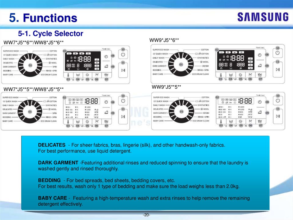
DELICATES - For sheer fabrics, bras, lingerie (silk), and other handwash-only fabrics.
For best performance, use liquid detergent.
DARK GARMENT -Featuring additional rinses and reduced spinning to ensure that the laundry is
washed gently and rinsed thoroughly.
BEDDING - For bed spreads, bed sheets, bedding covers, etc.
For best results, wash only 1 type of bedding and make sure the load weighs less than 2.0kg.
BABY CARE - Featuring a high-temperature wash and extra rinses to help remove the remaining
detergent effectively.
-20-
21.
5. Functions5-2. Cycle Options
WW7*J5**6**/WW8*J5**6**
WW9*J5**6**
WW7*J5**5**/WW8*J5**5**
WW9*J5**5**
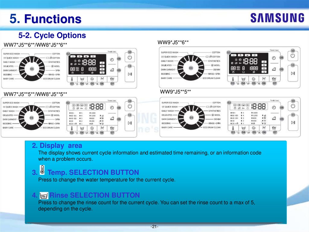
2. Display area
The display shows current cycle information and estimated time remaining, or an information code
when a problem occurs.
3.
Temp. SELECTION BUTTON
Press to change the water temperature for the current cycle.
4.
Rinse SELECTION BUTTON
Press to change the rinse count for the current cycle. You can set the rinse count to a max of 5,
depending on the cycle.
-21-
22.
5. Functions5-2. Cycle Options
WW7*J5**6**/WW8*J5**6**
WW9*J5**6**
WW7*J5**5**/WW8*J5**5**
WW9*J5**5**
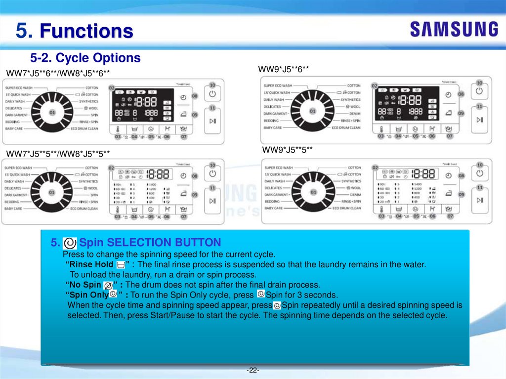
5.
Spin SELECTION BUTTON
Press to change the spinning speed for the current cycle.
“Rinse Hold ” : The final rinse process is suspended so that the laundry remains in the water.
To unload the laundry, run a drain or spin process.
“No Spin ” : The drum does not spin after the final drain process.
“Spin Only ” : To run the Spin Only cycle, press Spin for 3 seconds.
When the cycle time and spinning speed appear, press Spin repeatedly until a desired spinning speed is
selected. Then, press Start/Pause to start the cycle. The spinning time depends on the selected cycle.
-22-
23.
5. Functions5-2. Cycle Options
WW7*J5**6**/WW8*J5**6**
WW9*J5**6**
WW7*J5**5**/WW8*J5**5**
WW9*J5**5**
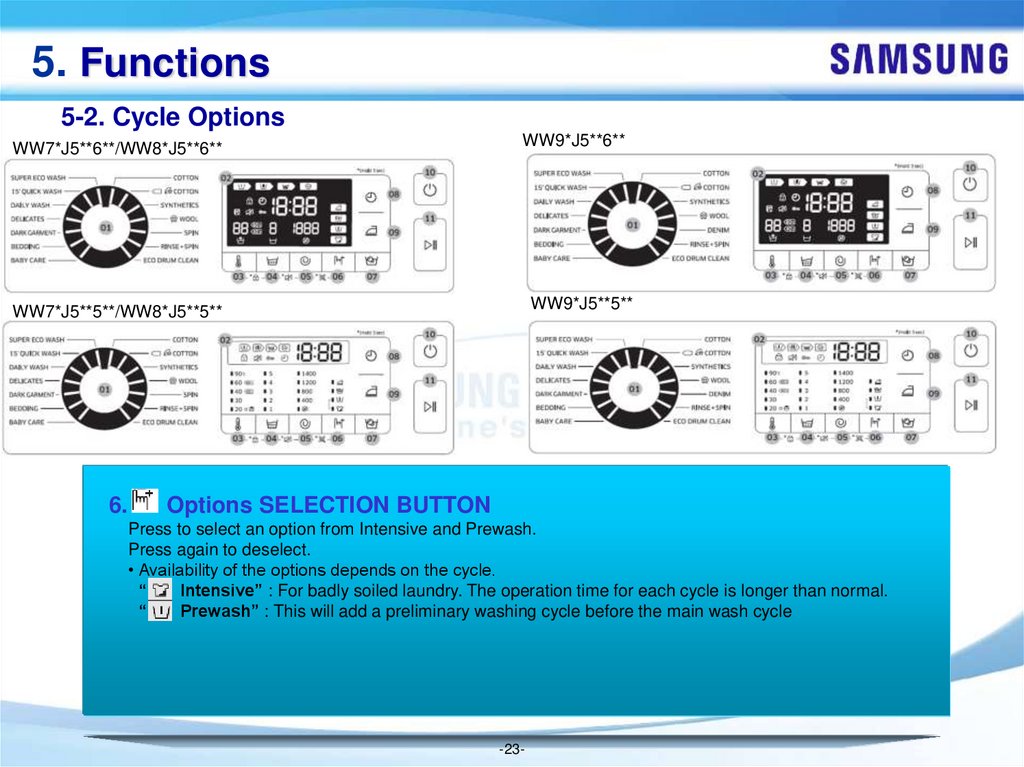
6.
Options SELECTION BUTTON
Press to select an option from Intensive and Prewash.
Press again to deselect.
• Availability of the options depends on the cycle.
“
Intensive” : For badly soiled laundry. The operation time for each cycle is longer than normal.
“
Prewash” : This will add a preliminary washing cycle before the main wash cycle
-23-
24.
5. Functions5-2. Cycle Options
WW7*J5**6**/WW8*J5**6**
WW9*J5**6**
WW7*J5**5**/WW8*J5**5**
WW9*J5**5**
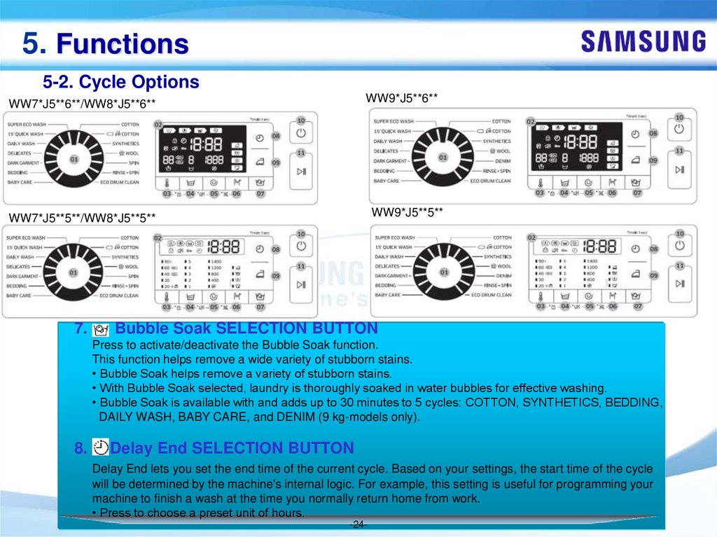
7.
Bubble Soak SELECTION BUTTON
Press to activate/deactivate the Bubble Soak function.
This function helps remove a wide variety of stubborn stains.
• Bubble Soak helps remove a variety of stubborn stains.
• With Bubble Soak selected, laundry is thoroughly soaked in water bubbles for effective washing.
• Bubble Soak is available with and adds up to 30 minutes to 5 cycles: COTTON, SYNTHETICS, BEDDING,
DAILY WASH, BABY CARE, and DENIM (9 kg-models only).
8.
Delay End SELECTION BUTTON
Delay End lets you set the end time of the current cycle. Based on your settings, the start time of the cycle
will be determined by the machine's internal logic. For example, this setting is useful for programming your
machine to finish a wash at the time you normally return home from work.
• Press to choose a preset unit of hours.
-24-
25.
5. Functions5-2. Cycle Options
WW7*J5**6**/WW8*J5**6**
WW9*J5**6**
WW7*J5**5**/WW8*J5**5**
WW9*J5**5**
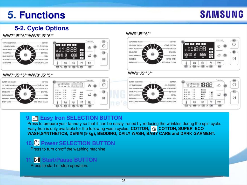
9.
Easy Iron SELECTION BUTTON
Press to prepare your laundry so that it can be easily ironed by reducing the wrinkles during the spin cycle.
Easy Iron is only available for the following wash cycles: COTTON,
COTTON, SUPER ECO
WASH,SYNTHETICS, DENIM (9 kg), BEDDING, DAILY WASH, BABY CARE and DARK GARMENT.
10.
Power SELECTION BUTTON
Press to turn on/off the washing machine.
11.
Start/Pause BUTTON
Press to start or stop operation.
-25-
26.
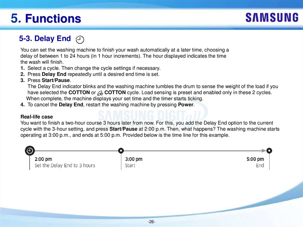
5. Functions5-3. Delay End
You can set the washing machine to finish your wash automatically at a later time, choosing a
delay of between 1 to 24 hours (in 1 hour increments). The hour displayed indicates the time
the wash will finish.
1. Select a cycle. Then change the cycle settings if necessary.
2. Press Delay End repeatedly until a desired end time is set.
3. Press Start/Pause.
The Delay End indicator blinks and the washing machine tumbles the drum to sense the weight of the load if you
have selected the COTTON or
COTTON cycle. Load sensing is preset and enabled only in these 2 cycles.
When complete, the machine displays your set time and the timer starts ticking.
4. To cancel the Delay End, restart the washing machine by pressing Power.
Real-life case
You want to finish a two-hour course 3 hours later from now. For this, you add the Delay End option to the current
cycle with the 3-hour setting, and press Start/Pause at 2:00 p.m. Then, what happens? The washing machine starts
operating at 3:00 p.m., and ends at 5:00 p.m. Provided below is the time line for this example.
-26-
27.
5. Functions5-4. Child Lock
To prevent accidents involving children, the Child Lock function locks all buttons except for Power..
• To set the Child Lock function, hold down
Temp. and
Rinse simultaneously for 3 seconds.
• To release the Child Lock function, hold down Temp. and
Rinse simultaneously for 3 seconds.
NOTE
In the Child Lock state, you must first release the Child Lock if you want to add detergent or laundry.
Your setting will be kept even after restarting the machine.
5-5. Sound On/Off
You can turn on or off the key. Your setting will remain effective after you restart the machine.
• To mute the sound, hold down
Rinse and
Spin simultaneously for 3 seconds.
• To unmute the sound, hold down again for 3 seconds.
-27-
28.
5. Functions5-6. Eco Drum Clean
Perform this cycle regularly to clean the drum and to remove bacteria.
1. Press Power to turn on the washing machine.
2. Turn the Cycle Selector to select ECO DRUM CLEAN.
3. Press Start/Pause.
NOTE
The water temperature for ECO DRUM CLEAN is set to 70 °C, which cannot be changed.
It is recommended to run the ECO DRUM CLEAN cycle once every 40 washes.
CAUTION
Do not use any cleaning agents for cleaning the drum. Chemical residue in the drum deteriorates
the washing performance.
ECO DRUM CLEAN reminder
The ECO DRUM CLEAN reminder appears on the main screen once every 40 washes. It is advisable to perform the
ECO DRUM CLEAN regularly.
When you first see this reminder, you can ignore the reminder for 6 consecutive washes. From the 7th wash, the
reminder no longer appears. However, it appears again on the next 40th wash.
-28-
29.
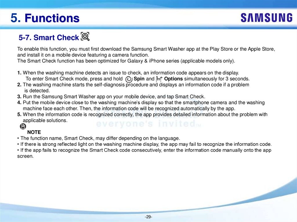
5. Functions5-7. Smart Check
To enable this function, you must first download the Samsung Smart Washer app at the Play Store or the Apple Store,
and install it on a mobile device featuring a camera function.
The Smart Check function has been optimized for Galaxy & iPhone series (applicable models only).
1. When the washing machine detects an issue to check, an information code appears on the display.
To enter Smart Check mode, press and hold
Spin and
Options simultaneously for 3 seconds.
2. The washing machine starts the self-diagnosis procedure and displays an information code if a problem
is detected.
3. Run the Samsung Smart Washer app on your mobile device, and tap Smart Check.
4. Put the mobile device close to the washing machine’s display so that the smartphone camera and the washing
machine face each other. Then, the information code will be recognized automatically by the app.
5. When the information code is recognized correctly, the app provides detailed information about the problem with
applicable solutions.
NOTE
• The function name, Smart Check, may differ depending on the language.
• If there is strong reflected light on the washing machine display, the app may fail to recognize the information code.
• If the app fails to recognize the Smart Check code consecutively, enter the information code manually onto the app
screen.
-29-
30.
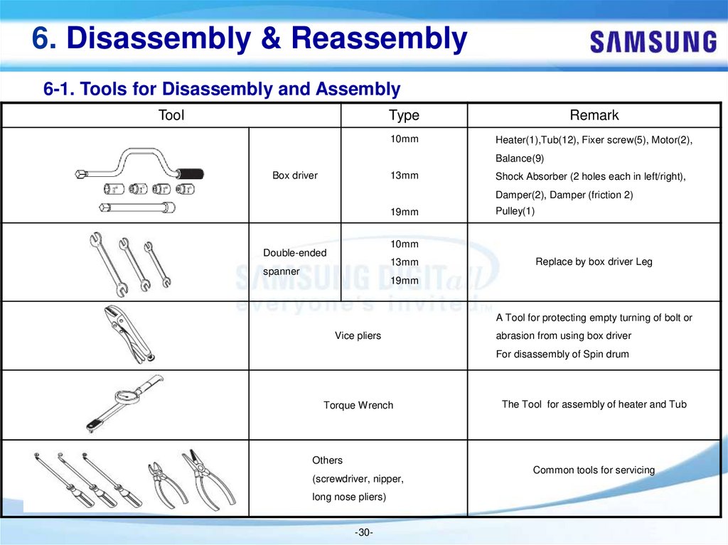
6. Disassembly & Reassembly6-1. Tools for Disassembly and Assembly
Tool
Type
Remark
10mm
Heater(1),Tub(12), Fixer screw(5), Motor(2),
Balance(9)
Box driver
13mm
Shock Absorber (2 holes each in left/right),
Damper(2), Damper (friction 2)
19mm
Pulley(1)
10mm
Double-ended
13mm
spanner
Replace by box driver Leg
19mm
A Tool for protecting empty turning of bolt or
Vice pliers
abrasion from using box driver
For disassembly of Spin drum
Torque Wrench
The Tool for assembly of heater and Tub
Others
(screwdriver, nipper,
long nose pliers)
-30-
Common tools for servicing
31.
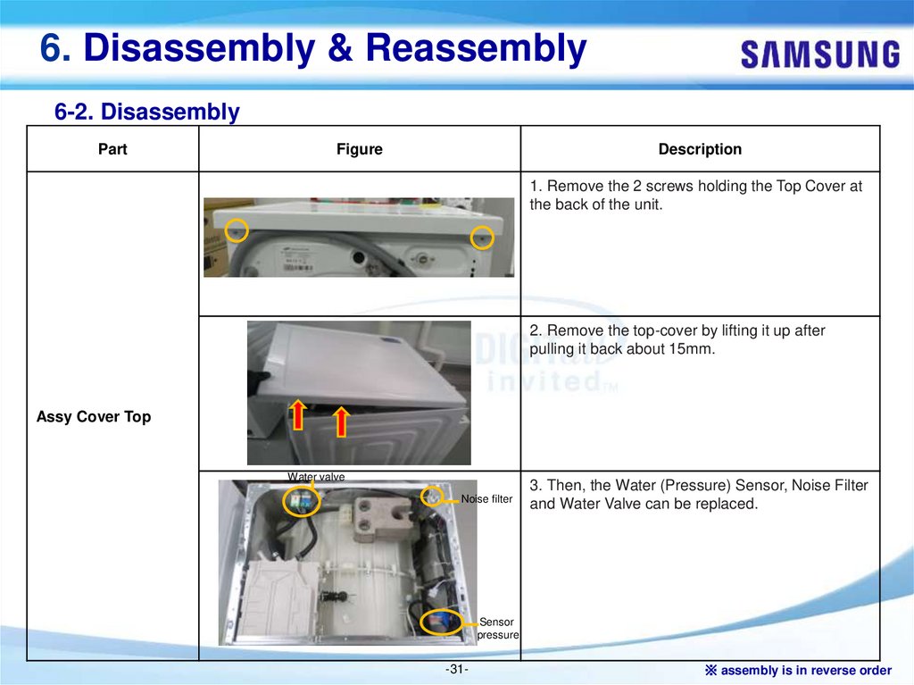
6. Disassembly & Reassembly6-2. Disassembly
Part
Figure
Description
1. Remove the 2 screws holding the Top Cover at
the back of the unit.
2. Remove the top-cover by lifting it up after
pulling it back about 15mm.
Assy Cover Top
Water valve
Noise filter
3. Then, the Water (Pressure) Sensor, Noise Filter
and Water Valve can be replaced.
Sensor
pressure
-31-
※ assembly is in reverse order
32.
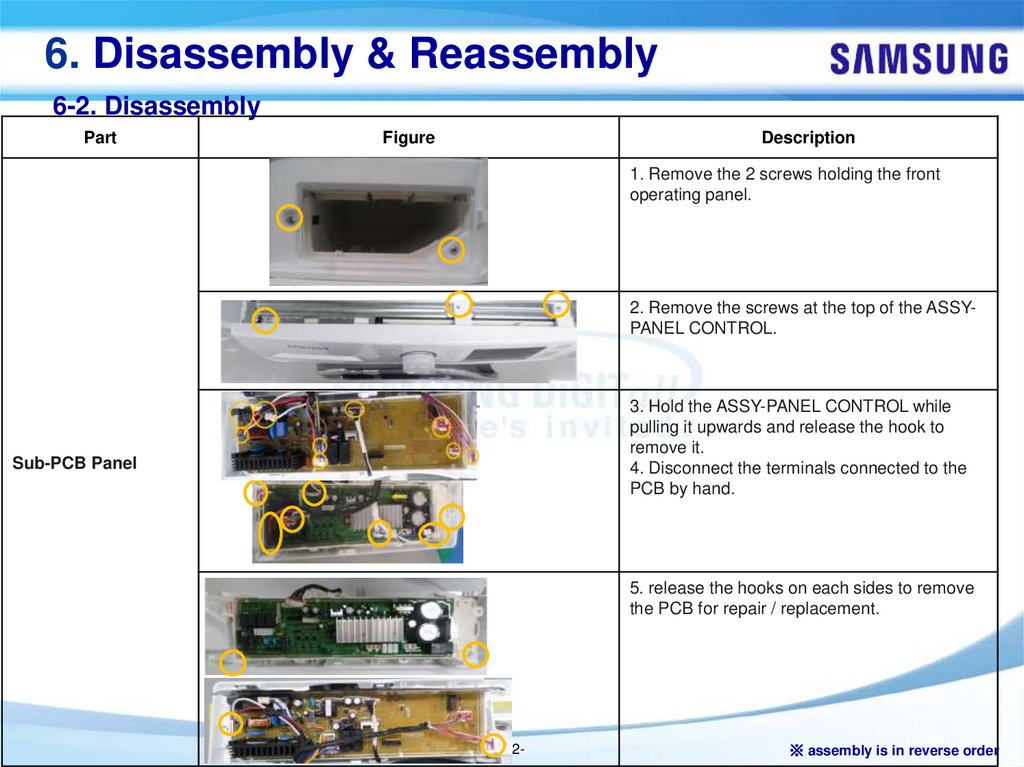
6. Disassembly & Reassembly6-2. Disassembly
Part
Figure
Description
1. Remove the 2 screws holding the front
operating panel.
2. Remove the screws at the top of the ASSYPANEL CONTROL.
3. Hold the ASSY-PANEL CONTROL while
pulling it upwards and release the hook to
remove it.
4. Disconnect the terminals connected to the
PCB by hand.
Sub-PCB Panel
5. release the hooks on each sides to remove
the PCB for repair / replacement.
-32-
※ assembly is in reverse order
33.
6. Disassembly & Reassembly6-2. Disassembly
Part
Figure
Description
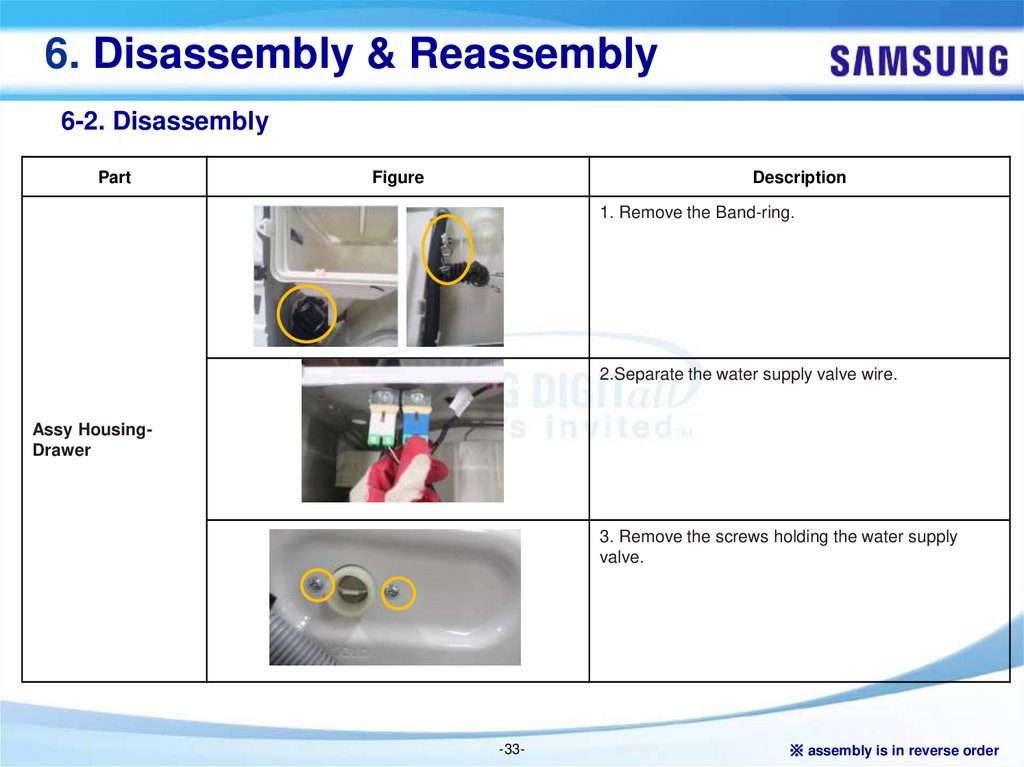
1. Remove the Band-ring.
2.Separate the water supply valve wire.
Assy HousingDrawer
3. Remove the screws holding the water supply
valve.
-33-
※ assembly is in reverse order
34.
6. Disassembly & Reassembly6-2. Disassembly
Part
Figure
Description
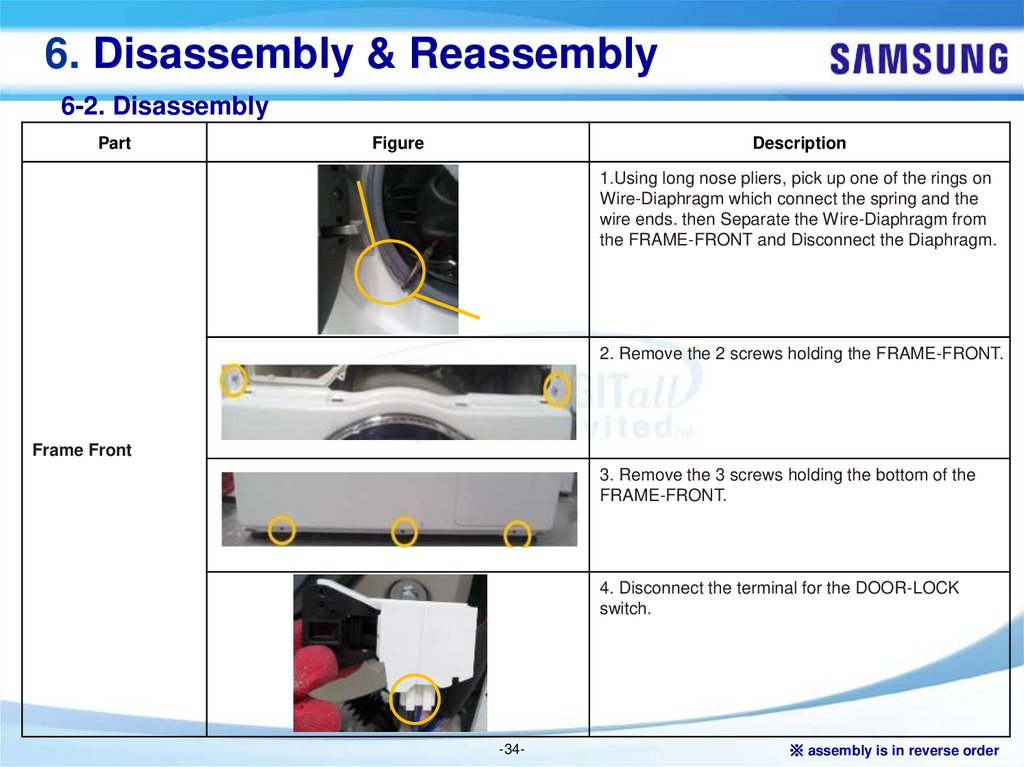
1.Using long nose pliers, pick up one of the rings on
Wire-Diaphragm which connect the spring and the
wire ends. then Separate the Wire-Diaphragm from
the FRAME-FRONT and Disconnect the Diaphragm.
2. Remove the 2 screws holding the FRAME-FRONT.
Frame Front
3. Remove the 3 screws holding the bottom of the
FRAME-FRONT.
4. Disconnect the terminal for the DOOR-LOCK
switch.
-34-
※ assembly is in reverse order
35.
6. Disassembly & Reassembly6-2. Disassembly
Part
Figure
Description
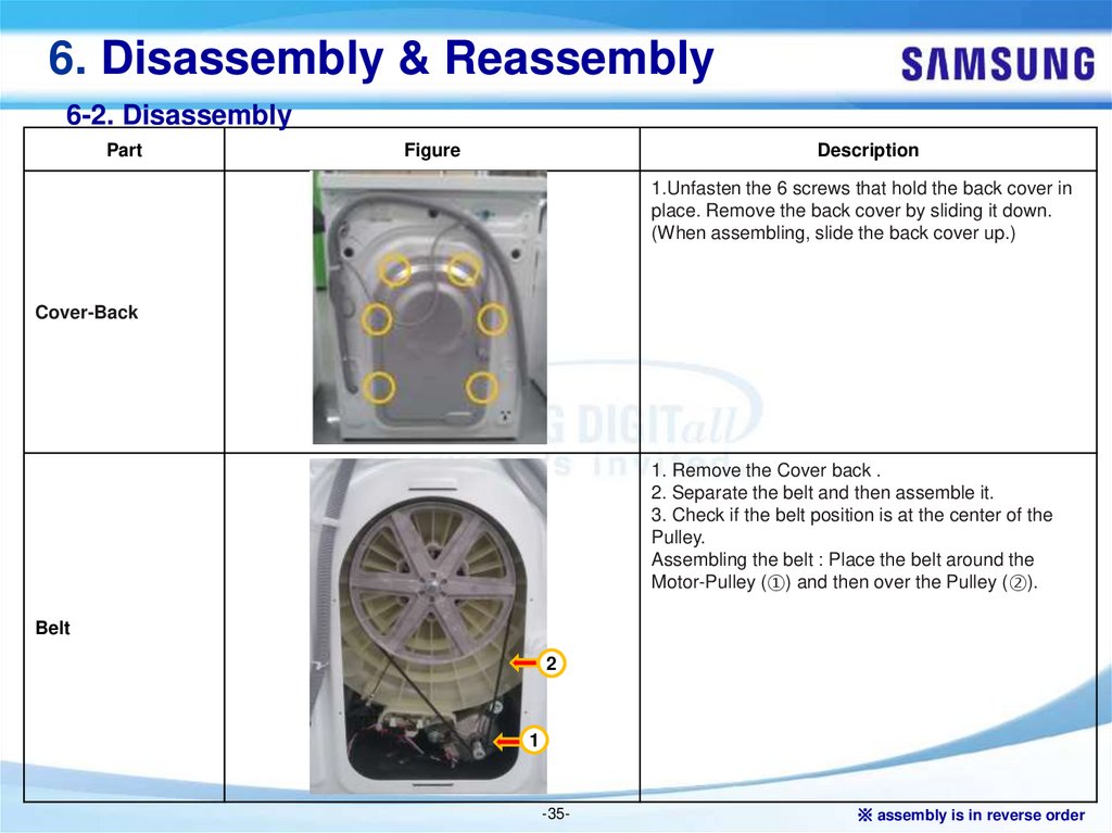
1.Unfasten the 6 screws that hold the back cover in
place. Remove the back cover by sliding it down.
(When assembling, slide the back cover up.)
Cover-Back
1. Remove the Cover back .
2. Separate the belt and then assemble it.
3. Check if the belt position is at the center of the
Pulley.
Assembling the belt : Place the belt around the
Motor-Pulley (①) and then over the Pulley (②).
Belt
2
1
-35-
※ assembly is in reverse order
36.
6. Disassembly & Reassembly6-2. Disassembly
Part
Figure
Description
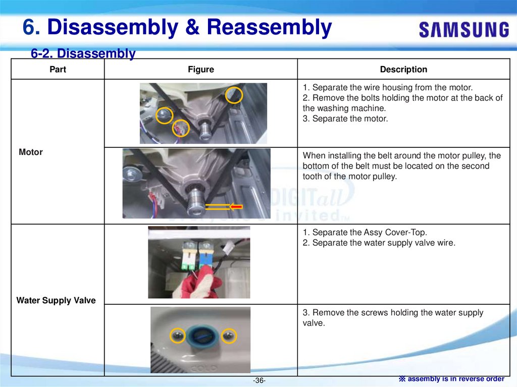
1. Separate the wire housing from the motor.
2. Remove the bolts holding the motor at the back of
the washing machine.
3. Separate the motor.
Motor
When installing the belt around the motor pulley, the
bottom of the belt must be located on the second
tooth of the motor pulley.
1. Separate the Assy Cover-Top.
2. Separate the water supply valve wire.
Water Supply Valve
3. Remove the screws holding the water supply
valve.
-36-
※ assembly is in reverse order
37.
6. Disassembly & Reassembly6-2. Disassembly
Part
Figure
Description
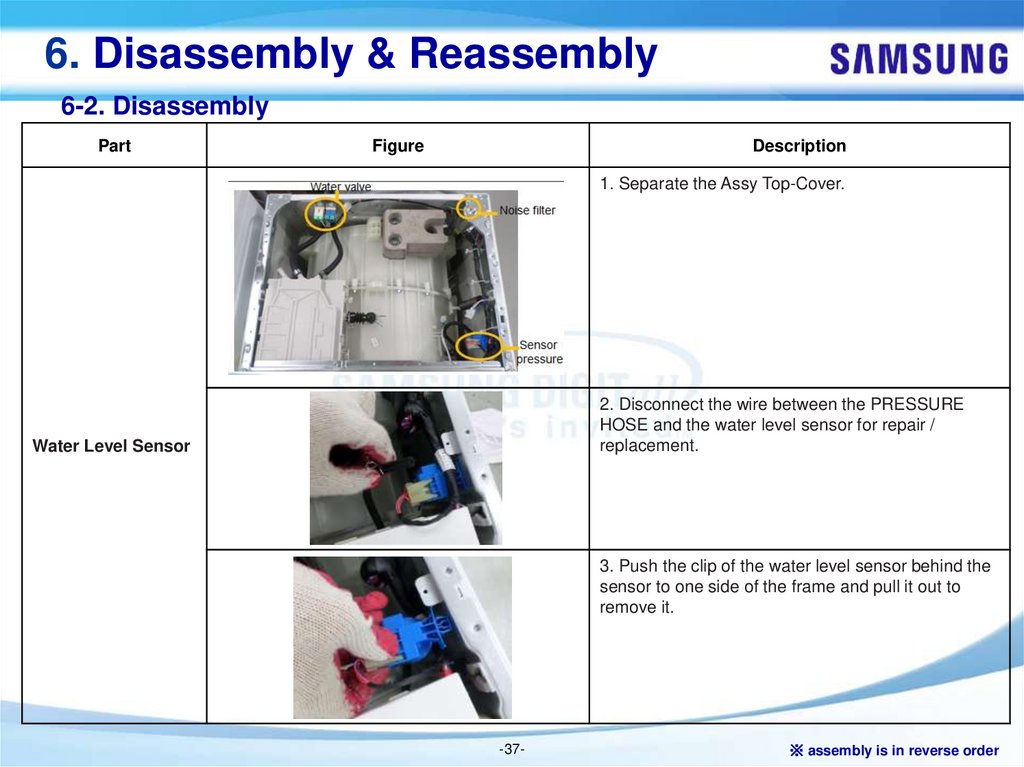
1. Separate the Assy Top-Cover.
2. Disconnect the wire between the PRESSURE
HOSE and the water level sensor for repair /
replacement.
Water Level Sensor
3. Push the clip of the water level sensor behind the
sensor to one side of the frame and pull it out to
remove it.
-37-
※ assembly is in reverse order
38.
6. Disassembly & Reassembly6-2. Disassembly
Part
Figure
Description
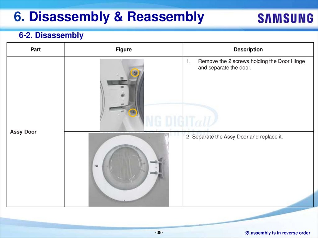
1.
Assy Door
Remove the 2 screws holding the Door Hinge
and separate the door.
2. Separate the Assy Door and replace it.
-38-
※ assembly is in reverse order
39.
6. Disassembly & Reassembly6-2. Disassembly
Part
Figure
Description
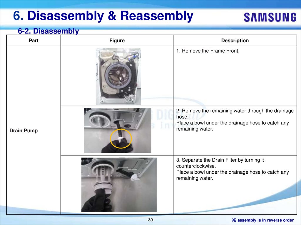
1. Remove the Frame Front.
2. Remove the remaining water through the drainage
hose.
Place a bowl under the drainage hose to catch any
remaining water.
Drain Pump
3. Separate the Drain Filter by turning it
counterclockwise.
Place a bowl under the drainage hose to catch any
remaining water.
-39-
※ assembly is in reverse order
40.
6. Disassembly & Reassembly6-2. Disassembly
Part
Figure
Description
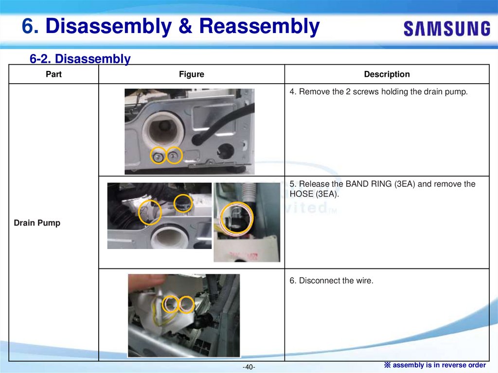
4. Remove the 2 screws holding the drain pump.
5. Release the BAND RING (3EA) and remove the
HOSE (3EA).
Drain Pump
6. Disconnect the wire.
-40-
※ assembly is in reverse order
41.
6. Disassembly & Reassembly6-2. Disassembly
Part
Figure
Description
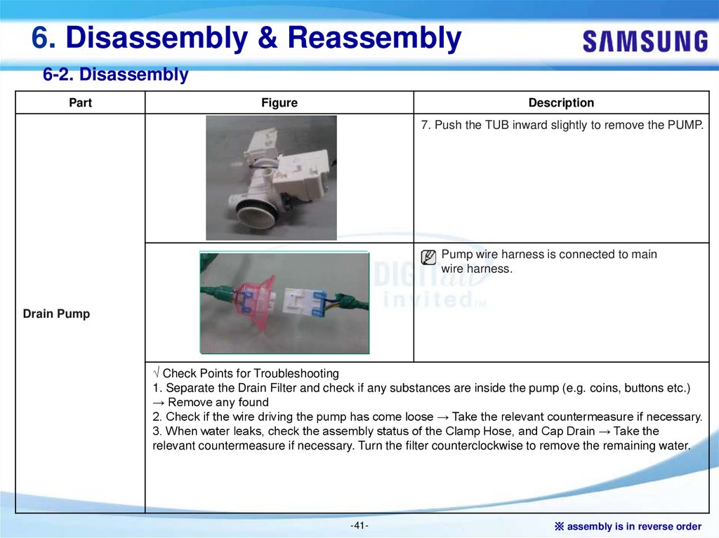
7. Push the TUB inward slightly to remove the PUMP.
Pump wire harness is connected to main
wire harness.
Drain Pump
√ Check Points for Troubleshooting
1. Separate the Drain Filter and check if any substances are inside the pump (e.g. coins, buttons etc.)
→ Remove any found
2. Check if the wire driving the pump has come loose → Take the relevant countermeasure if necessary.
3. When water leaks, check the assembly status of the Clamp Hose, and Cap Drain → Take the
relevant countermeasure if necessary. Turn the filter counterclockwise to remove the remaining water.
-41-
※ assembly is in reverse order
42.
6. Disassembly & Reassembly6-2. Disassembly
Part
Figure
Description
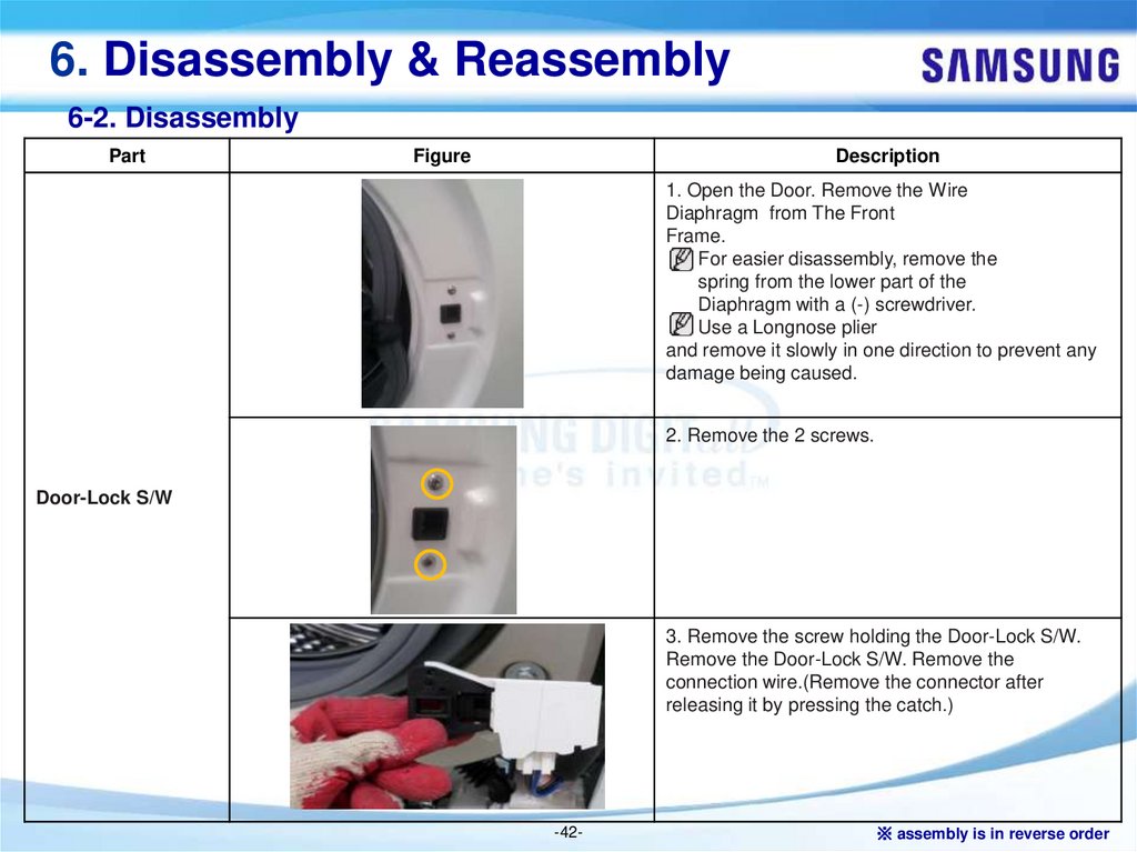
1. Open the Door. Remove the Wire
Diaphragm from The Front
Frame.
For easier disassembly, remove the
spring from the lower part of the
Diaphragm with a (-) screwdriver.
Use a Longnose plier
and remove it slowly in one direction to prevent any
damage being caused.
2. Remove the 2 screws.
Door-Lock S/W
3. Remove the screw holding the Door-Lock S/W.
Remove the Door-Lock S/W. Remove the
connection wire.(Remove the connector after
releasing it by pressing the catch.)
-42-
※ assembly is in reverse order
43.
6. Disassembly & Reassembly6-2. Disassembly
Part
Figure
Description
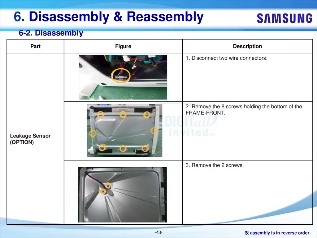
1. Disconnect two wire connectors.
2. Remove the 8 screws holding the bottom of the
FRAME-FRONT.
Leakage Sensor
(OPTION)
3. Remove the 2 screws.
-43-
※ assembly is in reverse order
44.
6. Disassembly & Reassembly6-2. Disassembly
Part
Figure
Description
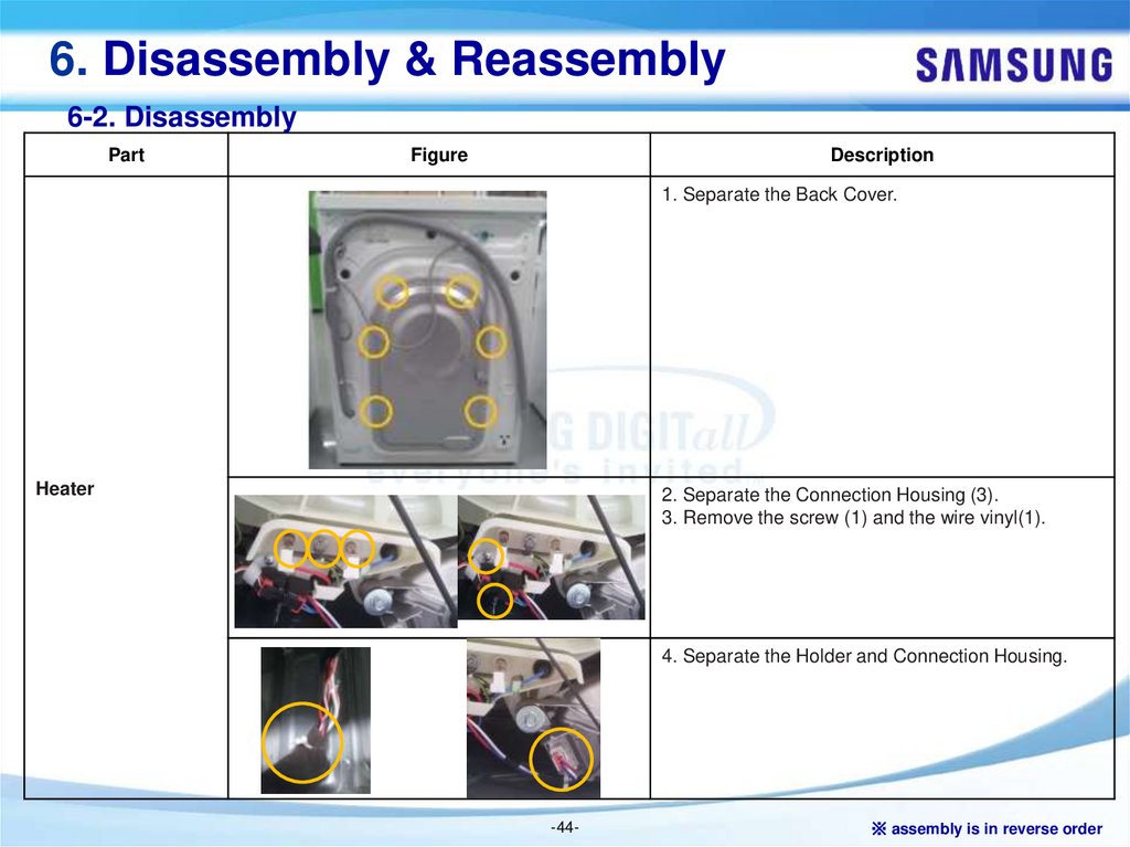
1. Separate the Back Cover.
Heater
2. Separate the Connection Housing (3).
3. Remove the screw (1) and the wire vinyl(1).
4. Separate the Holder and Connection Housing.
-44-
※ assembly is in reverse order
45.
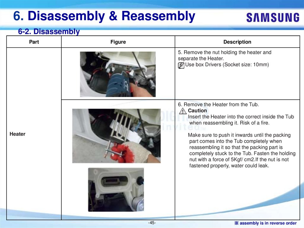
6. Disassembly & Reassembly6-2. Disassembly
Part
Figure
Description
5. Remove the nut holding the heater and
separate the Heater.
Use box Drivers (Socket size: 10mm)
6. Remove the Heater from the Tub.
Caution
Insert the Heater into the correct inside the Tub
when reassembling it. Risk of a fire.
Heater
Make sure to push it inwards until the packing
part comes into the Tub completely when
reassembling it so that the packing part is
completely stuck to the Tub. Fasten the holding
nut with a force of 5Kgf/ cm2.If the nut is not
fastened properly, water could leak.
-45-
※ assembly is in reverse order
46.
6. Disassembly & Reassembly6-2. Disassembly
Part
Figure
Description
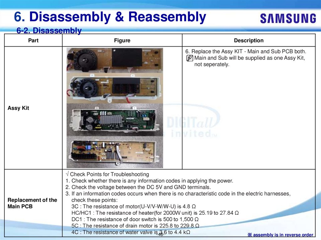
6. Replace the Assy KIT - Main and Sub PCB both.
Main and Sub will be supplied as one Assy Kit,
not seperately.
Assy Kit
Replacement of the
Main PCB
√ Check Points for Troubleshooting
1. Check whether there is any information codes in applying the power.
2. Check the voltage between the DC 5V and GND terminals.
3. If an information codes occurs when there is no characteristic code in the electric harnesses,
check these points:
3C : The resistance of motor(U-V/V-W/W-U) is 4.8 Ω
HC/HC1 : The resistance of heater(for 2000W unit) is 25.19 to 27.84 Ω
DC1 : The resistance of door switch is 500 to 1,500 Ω
5C : The resistance of drain motor is 225.8 to 229.8 Ω
4C : The resistance of water valve is-463.6 to 4.4 kΩ
※ assembly is in reverse order
47.
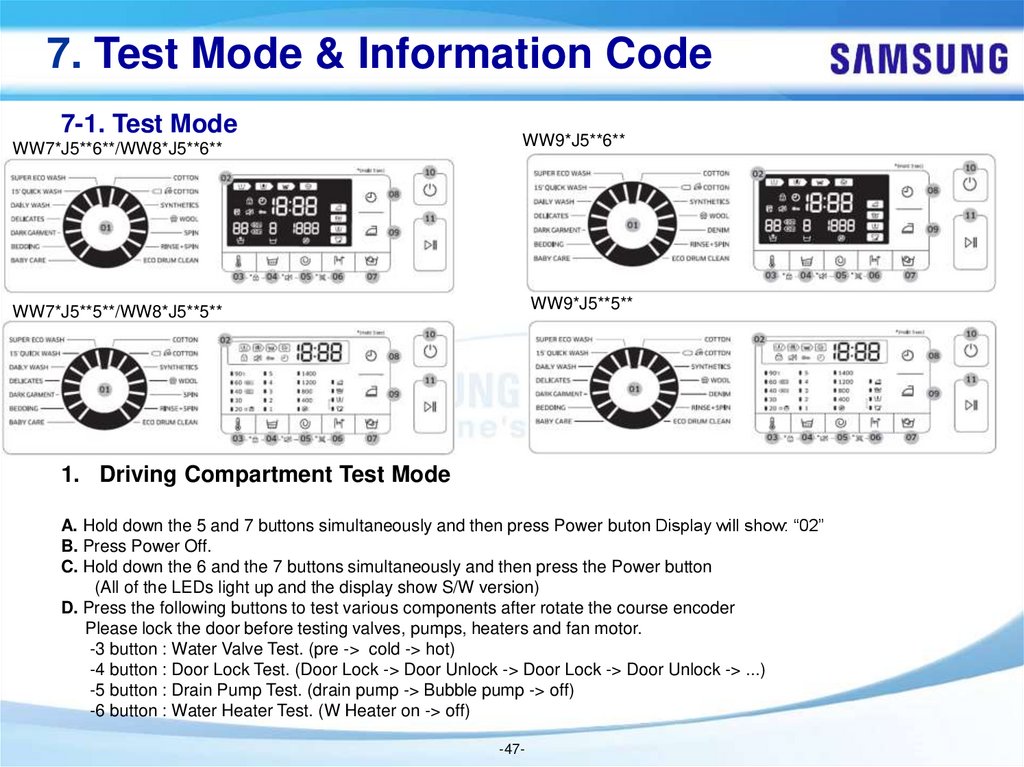
7. Test Mode & Information Code7-1. Test Mode
WW7*J5**6**/WW8*J5**6**
WW9*J5**6**
WW7*J5**5**/WW8*J5**5**
WW9*J5**5**
1. Driving Compartment Test Mode
A. Hold down the 5 and 7 buttons simultaneously and then press Power buton Display will show: “02”
B. Press Power Off.
C. Hold down the 6 and the 7 buttons simultaneously and then press the Power button
(All of the LEDs light up and the display show S/W version)
D. Press the following buttons to test various components after rotate the course encoder
Please lock the door before testing valves, pumps, heaters and fan motor.
-3 button : Water Valve Test. (pre -> cold -> hot)
-4 button : Door Lock Test. (Door Lock -> Door Unlock -> Door Lock -> Door Unlock -> ...)
-5 button : Drain Pump Test. (drain pump -> Bubble pump -> off)
-6 button : Water Heater Test. (W Heater on -> off)
-47-
48.
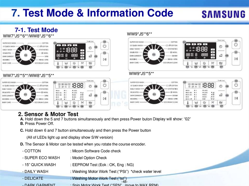
7. Test Mode & Information Code7-1. Test Mode
WW7*J5**6**/WW8*J5**6**
WW9*J5**6**
WW7*J5**5**/WW8*J5**5**
WW9*J5**5**
2. Sensor & Motor Test
A. Hold down the 5 and 7 buttons simultaneously and then press Power buton Display will show: “02”
B. Press Power Off.
C. Hold down 6 and 7 button simultaneously and then press the Power button
(All of LEDs light up and display show S/W version)
D. The Sensor & Motor can be tested when you rotate the course encoder.
- COTTON
: Micom Software Code check
- SUPER ECO WASH
: Model Option Check
- 15” QUICK WASH
: EEPROM Test (Eok : OK, Eng : NG)
- DAILY WASH
: Washing Motor Work Test (“PSt”) *check water level
- DELICATE
: Washing Motor Work Test (“tst”)
-48-
49.
7. Test Mode & Information Code7-1. Test Mode
WW7*J5**6**/WW8*J5**6**
WW9*J5**6**
WW7*J5**5**/WW8*J5**5**
WW9*J5**5**
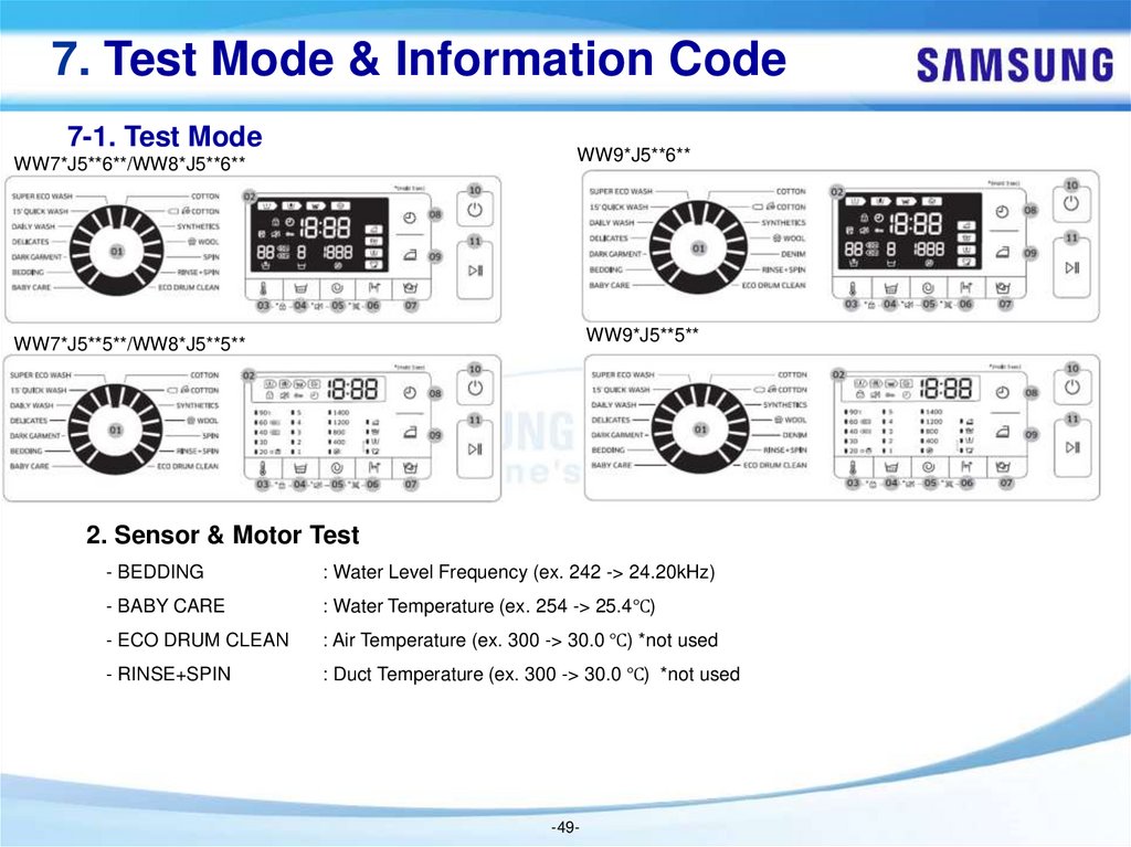
2. Sensor & Motor Test
- BEDDING
: Water Level Frequency (ex. 242 -> 24.20kHz)
- BABY CARE
: Water Temperature (ex. 254 -> 25.4℃)
- ECO DRUM CLEAN
: Air Temperature (ex. 300 -> 30.0 ℃) *not used
- RINSE+SPIN
: Duct Temperature (ex. 300 -> 30.0 ℃) *not used
-49-
50.
7. Test Mode & Information Code7-2. Information Code
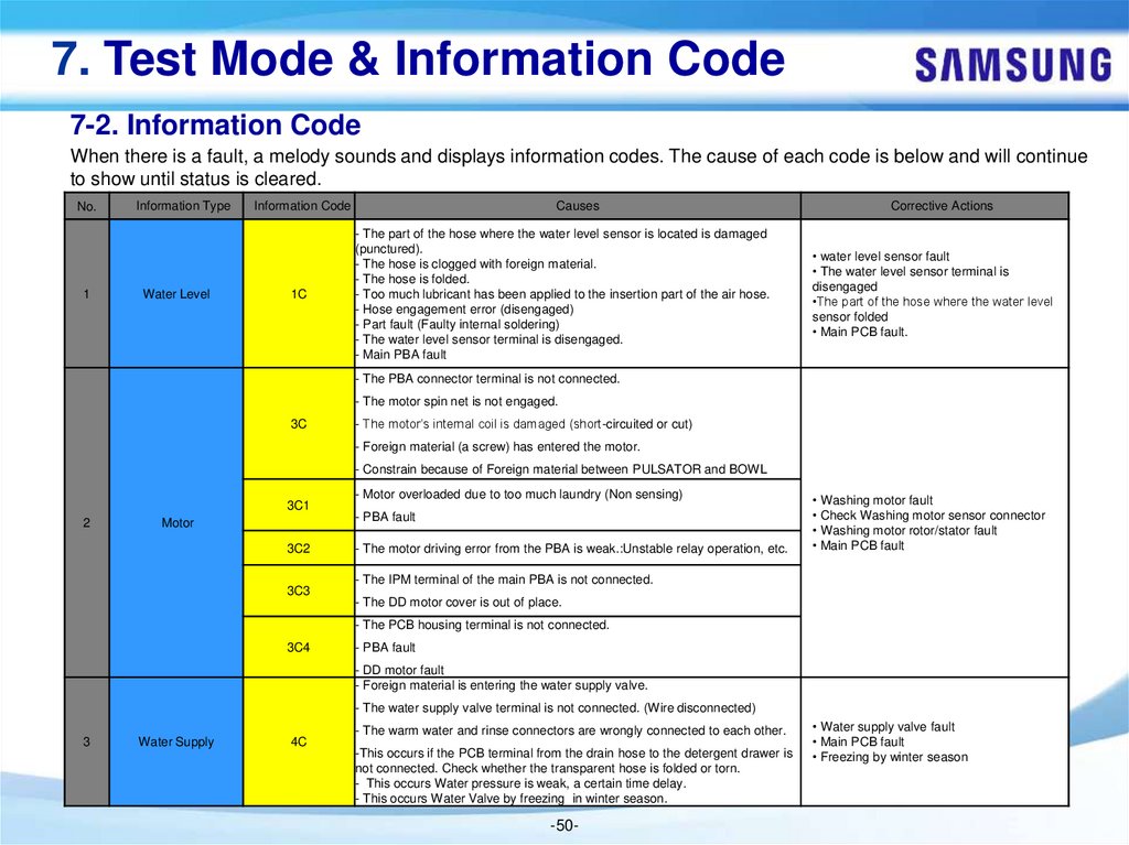
When there is a fault, a melody sounds and displays information codes. The cause of each code is below and will continue
to show until status is cleared.
No.
1
Information Type
Water Level
Information Code
1C
Causes
- The part of the hose where the water level sensor is located is damaged
(punctured).
- The hose is clogged with foreign material.
- The hose is folded.
- Too much lubricant has been applied to the insertion part of the air hose.
- Hose engagement error (disengaged)
- Part fault (Faulty internal soldering)
- The water level sensor terminal is disengaged.
- Main PBA fault
Corrective Actions
• water level sensor fault
• The water level sensor terminal is
disengaged
•The part of the hose where the water level
sensor folded
• Main PCB fault.
- The PBA connector terminal is not connected.
- The motor spin net is not engaged.
3C
- The motor’s internal coil is damaged (short-circuited or cut)
- Foreign material (a screw) has entered the motor.
- Constrain because of Foreign material between PULSATOR and BOWL
3C1
2
Motor
3C2
3C3
- Motor overloaded due to too much laundry (Non sensing)
- PBA fault
- The motor driving error from the PBA is weak.:Unstable relay operation, etc.
• Washing motor fault
• Check Washing motor sensor connector
• Washing motor rotor/stator fault
• Main PCB fault
- The IPM terminal of the main PBA is not connected.
- The DD motor cover is out of place.
- The PCB housing terminal is not connected.
3C4
- PBA fault
- DD motor fault
- Foreign material is entering the water supply valve.
- The water supply valve terminal is not connected. (Wire disconnected)
3
Water Supply
4C
- The warm water and rinse connectors are wrongly connected to each other.
-This occurs if the PCB terminal from the drain hose to the detergent drawer is
not connected. Check whether the transparent hose is folded or torn.
- This occurs Water pressure is weak, a certain time delay.
- This occurs Water Valve by freezing in winter season.
-50-
• Water supply valve fault
• Main PCB fault
• Freezing by winter season
51.
7. Test Mode & Information Code7-2. Information Code
No.
Information Type
Information Code
3
Water Supply
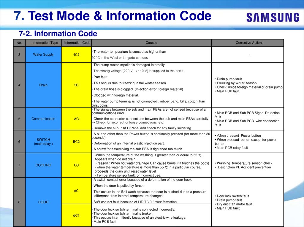
4C2
Causes
- The water temperature is sensed as higher than
50 ˚C in the Wool or Lingerie courses
Corrective Actions
-
- The pump motor impeller is damaged internally.
- The wrong voltage (220 V → 110 V) is supplied to the parts.
- Part fault
4
Drain
5C
- This occurs due to freezing in the winter season.
- The drain hose is clogged. (Injection error, foreign material)
• Drain pump fault
• Freezing by winter season
• Check inside foreign material of drain pump
• Main PCB fault
- Clogged with foreign material.
- The water pump terminal is not connected : rubber band, bills, cotton, hair
pins, coins.
- The signals between the sub and main PBAs are not sensed because of a
communications error.
5
Communication
AC
- Check the connector connections between the sub and main PBAs carefully.
→ Check for incorrect or loose connections, etc.
• Main PCB and Sub PCB Signal Detection
fault
• Main PCB and Sub PCB wire connection
fault
- Remove the sub PBA C/Panel and check for any faulty soldering.
6
SWITCH
(main relay )
- A button other than the Power button is continually pressed (for more than 30
seconds).
BC2
- Deformation of an internal plastic injection part.
- A screw for assembling the sub PBA is tightened too much.
7
COOLING
CC
-When the temperature of the washing is greater than or equal to 55 ℃,
Appears when do not drain.
(reason : When hot water drainage Can cause burns if it touches the body)
- when the water temperature is more than 55 ℃ in a particular course,
proceeds the drain until reset water level
- Temperature sensor fault, or incorrect use.
- A switch contact error because of a deformation of the door hook.
• When pressed Power button
• When pressed button except for power
button
• Main PCB relay fault
• Washing temperature sensor check
• Description PL Accident prevention
- When the door is pulled by force.
dC
8
- This occurs in the Boil wash because the door is pushed due to a pressure
difference from internal temperature changes.
- S/W contact fault because of LID TC “L” transformation.
DOOR
dC1
- The door lock switch terminal is connected incorrectly.
- The door lock switch terminal is broken.
- This occurs intermittently because of an electric wire leakage.
- Main PCB fault
-51-
• Door lock switch fault
• Drain pump fault
• Dry duct fan motor fault
• Main PCB fault
52.
7. Test Mode & Information Code7-2. Information Code
No.
8
Information Type
DOOR
Information Code
Causes
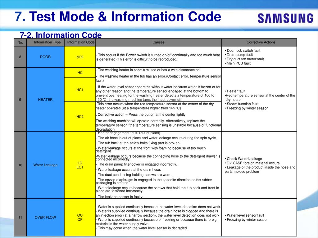
dC2
- This occurs if the Power switch is turned on/off continually and too much heat
is generated (This error is difficult to be reproduced.)
HC
Corrective Actions
• Door lock switch fault
• Drain pump fault
• Dry duct fan motor fault
• Main PCB fault
- The washing heater is short-circuited or has a wire disconnected.
- The washing heater in the tub has an error.(Contact error, temperature sensor
fault)
HC1
9
HEATER
HC2
10
Water Leakage
LC
LC1
- If the water level sensor operates without water because water is frozen or for
any other reason and the temperature sensor engaged at the bottom to
prevent overheating for the washing heater detects a temperature of 100 to
150 ˚C, the washing machine turns the input power off.
-This error occurs when the red temperature sensor at the center of the dry
heater operates (at a temperature higher than 145 ˚C)
• Heater fault
•Red temperature sensor at the center of the
dry heater
• Steam function fault
• Freezing by winter season
: Corrective action – Press the button at the center lightly.
The washing machine will operate normally. Alternatively, replace the
temperature sensor ifthe temperature sensing is unstable because of functional
degradation.
- Heater engagement fault. (out of place)
- The air hose is out of place and water leakage occurs during the spin cycle.
- The tub back at the safety bolts fixing part is broken.
- Water leakage occurs at the front with foaming because of too much
detergent.
-Water leakage occurs because the connecting hose to the detergent drawer is
connected incorrectly.
- The drain pump filter cover is engaged incorrectly.
- Water leakage occurs at the drain hose.
- The duct condensing holding screws are worn.
- The nozzle-diaphragm is engaged in the opposite direction or the rubber
packaging is omitted.
- Water leakage occurs because the screws that hold the tub back and front in
place are fastened incorrectly.
• Check Water Leakage
• DV CASE foreign material occurs
• Leakage of the product inside the hose and
parts molded problem
- The leakage sensor is faulty.
11
OVER FLOW
OC
OF
- Water is supplied continually because the water level detection does not work.
- Water is supplied continually because the drain hose is clogged and there is
an injection error (at a narrow section), the water level detection does not work • Water level sensor fault
- Water is supplied continually because of freezing or because there is foreign
• Freezing by winter season
material in the water supply valve.
- This may occur when the water level sensor is degraded.
-52-
53.
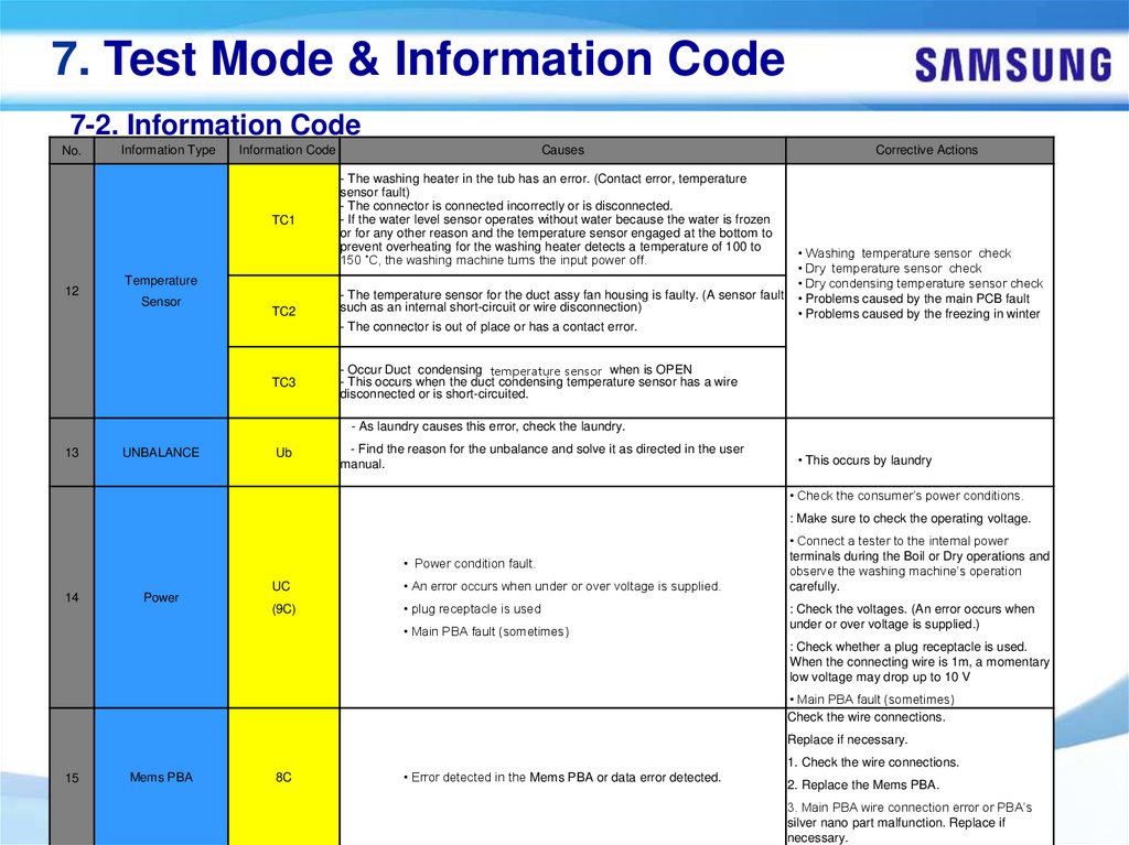
7. Test Mode & Information Code7-2. Information Code
No.
12
Information Type
Information Code
Causes
TC1
- The washing heater in the tub has an error. (Contact error, temperature
sensor fault)
- The connector is connected incorrectly or is disconnected.
- If the water level sensor operates without water because the water is frozen
or for any other reason and the temperature sensor engaged at the bottom to
prevent overheating for the washing heater detects a temperature of 100 to
150 ˚C, the washing machine turns the input power off.
Temperature
Sensor
TC2
- The temperature sensor for the duct assy fan housing is faulty. (A sensor fault
such as an internal short-circuit or wire disconnection)
Corrective Actions
• Washing temperature sensor check
• Dry temperature sensor check
• Dry condensing temperature sensor check
• Problems caused by the main PCB fault
• Problems caused by the freezing in winter
- The connector is out of place or has a contact error.
TC3
- Occur Duct condensing temperature sensor when is OPEN
- This occurs when the duct condensing temperature sensor has a wire
disconnected or is short-circuited.
- As laundry causes this error, check the laundry.
13
UNBALANCE
Ub
- Find the reason for the unbalance and solve it as directed in the user
manual.
• This occurs by laundry
• Check the consumer’s power conditions.
: Make sure to check the operating voltage.
• Power condition fault.
14
Power
UC
• An error occurs when under or over voltage is supplied.
(9C)
• plug receptacle is used
• Main PBA fault (sometimes)
• Connect a tester to the internal power
terminals during the Boil or Dry operations and
observe the washing machine’s operation
carefully.
: Check the voltages. (An error occurs when
under or over voltage is supplied.)
: Check whether a plug receptacle is used.
When the connecting wire is 1m, a momentary
low voltage may drop up to 10 V
• Main PBA fault (sometimes)
Check the wire connections.
Replace if necessary.
1. Check the wire connections.
15
Mems PBA
8C
• Error detected in the Mems PBA or data error detected.
-53-
2. Replace the Mems PBA.
3. Main PBA wire connection error or PBA’s
silver nano part malfunction. Replace if
necessary.
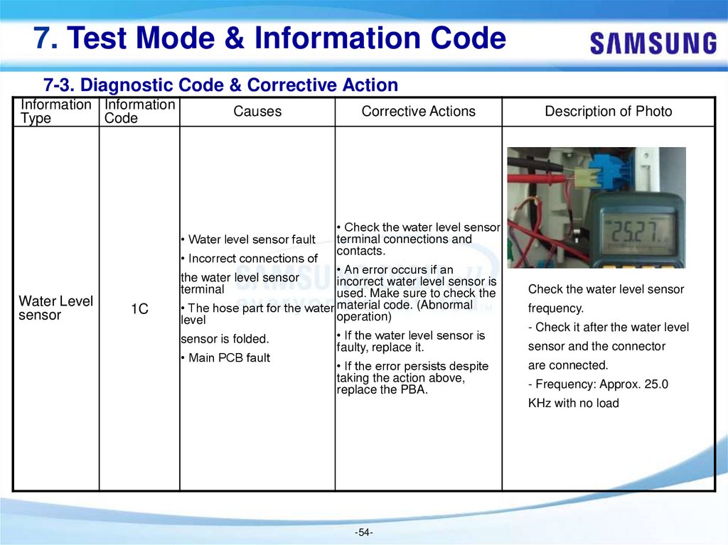
54.
7. Test Mode & Information Code7-3. Diagnostic Code & Corrective Action
Information Information
Type
Code
Causes
• Water level sensor fault
• Incorrect connections of
Water Level
sensor
Corrective Actions
• Check the water level sensor
terminal connections and
contacts.
• An error occurs if an
incorrect water level sensor is
used. Make sure to check the
• The hose part for the water material code. (Abnormal
operation)
level
the water level sensor
terminal
1C
sensor is folded.
• Main PCB fault
Description of Photo
Check the water level sensor
frequency.
• If the water level sensor is
faulty, replace it.
- Check it after the water level
• If the error persists despite
taking the action above,
replace the PBA.
are connected.
sensor and the connector
- Frequency: Approx. 25.0
KHz with no load
-54-
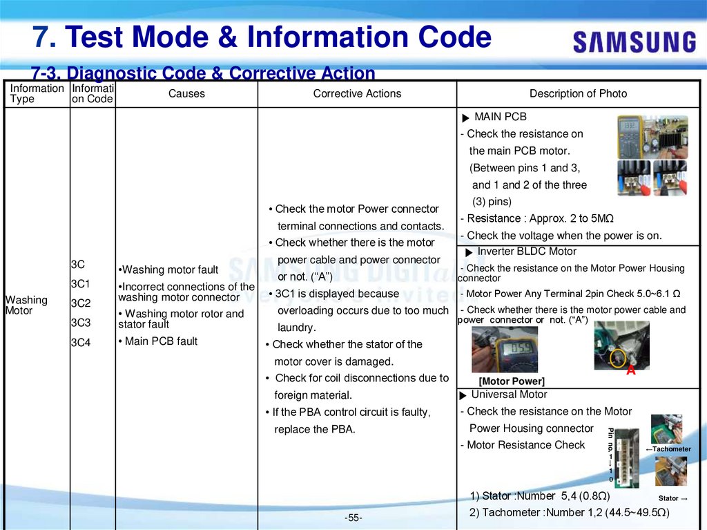
55.
7. Test Mode & Information Code7-3. Diagnostic Code & Corrective Action
Information Informati
Type
on Code
Causes
Corrective Actions
Description of Photo
▶ MAIN PCB
- Check the resistance on
the main PCB motor.
(Between pins 1 and 3,
and 1 and 2 of the three
• Check the motor Power connector
terminal connections and contacts.
• Check whether there is the motor
3C
3C1
Washing
Motor
3C2
•Washing motor fault
•Incorrect connections of the
washing motor connector
3C3
• Washing motor rotor and
stator fault
3C4
• Main PCB fault
power cable and power connector
or not. (“A”)
• 3C1 is displayed because
overloading occurs due to too much
laundry.
(3) pins)
- Resistance : Approx. 2 to 5MΩ
- Check the voltage when the power is on.
▶ Inverter BLDC Motor
- Check the resistance on the Motor Power Housing
connector
- Motor Power Any Terminal 2pin Check 5.0~6.1 Ω
- Check whether there is the motor power cable and
power connector or not. (“A”)
• Check whether the stator of the
motor cover is damaged.
• Check for coil disconnections due to
foreign material.
• If the PBA control circuit is faulty,
▶ Universal Motor
- Check the resistance on the Motor
Power Housing connector
- Motor Resistance Check
Pin no.
replace the PBA.
A
[Motor Power]
←Tachometer
→
1
1
0
1) Stator :Number 5,4 (0.8Ω)
-55-
Stator →
2) Tachometer :Number 1,2 (44.5~49.5Ω)
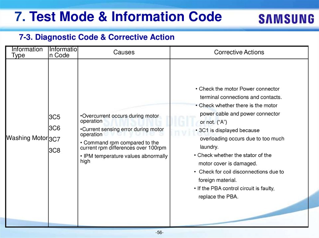
56.
7. Test Mode & Information Code7-3. Diagnostic Code & Corrective Action
Information
Type
Informatio
n Code
Causes
Corrective Actions
• Check the motor Power connector
terminal connections and contacts.
• Check whether there is the motor
3C5
•Overcurrent occurs during motor
operation
3C6
•Current sensing error during motor
operation
Washing Motor 3C7
3C8
• Command rpm compared to the
current rpm differences over 100rpm
• IPM temperature values abnormally
high
power cable and power connector
or not. (“A”)
• 3C1 is displayed because
overloading occurs due to too much
laundry.
• Check whether the stator of the
motor cover is damaged.
• Check for coil disconnections due to
foreign material.
• If the PBA control circuit is faulty,
replace the PBA.
-56-
57.
7. Test Mode & Information Code7-3. Diagnostic Code & Corrective Action
Informa Infor
matio
tion
n
Type
Code
Causes
Corrective Actions
Description of Photo
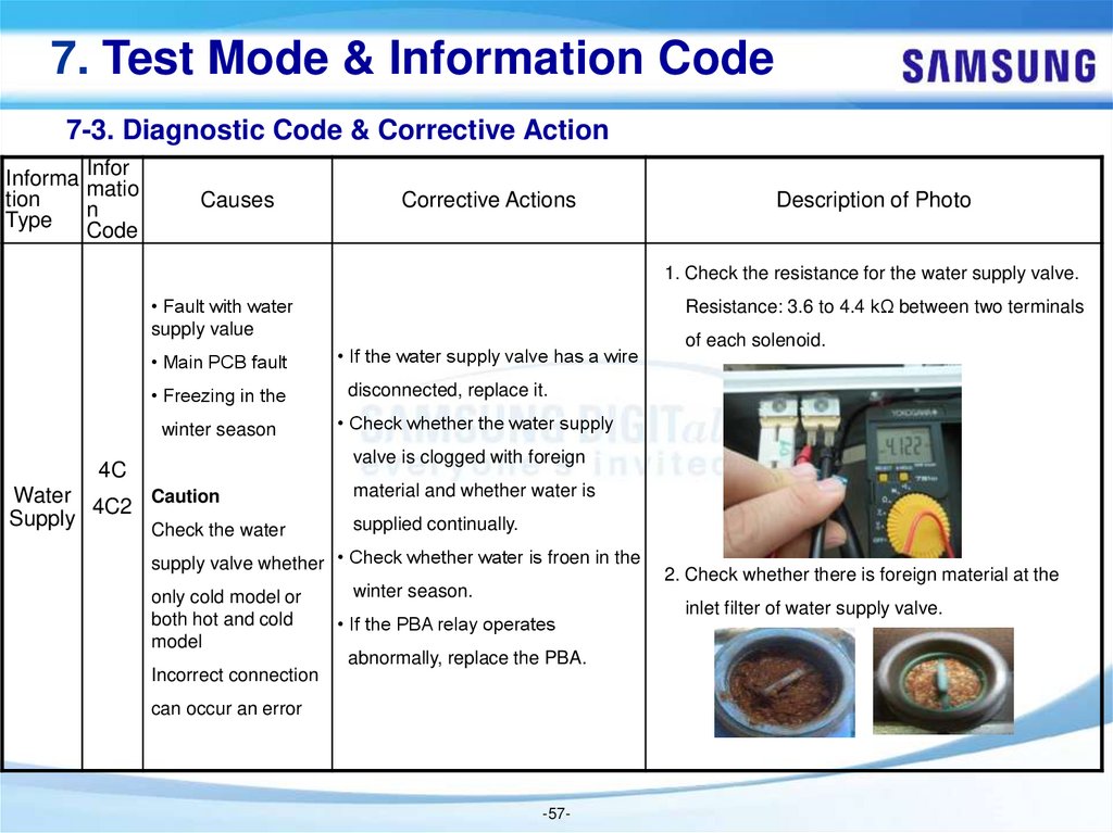
1. Check the resistance for the water supply valve.
• Fault with water
supply value
Resistance: 3.6 to 4.4 kΩ between two terminals
• Main PCB fault
• If the water supply valve has a wire
• Freezing in the
disconnected, replace it.
winter season
• Check whether the water supply
of each solenoid.
valve is clogged with foreign
4C
Water
Caution
4C2
Supply
Check the water
material and whether water is
supplied continually.
supply valve whether • Check whether water is froen in the
winter season.
only cold model or
both hot and cold
• If the PBA relay operates
model
abnormally, replace the PBA.
Incorrect connection
can occur an error
-57-
2. Check whether there is foreign material at the
inlet filter of water supply valve.
58.
7. Test Mode & Information Code7-3. Diagnostic Code & Corrective Action
Informa Inform
tion
ation
Type
Code
Causes
Corrective Actions
Description of Photo
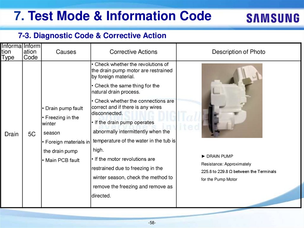
• Check whether the revolutions of
the drain pump motor are restrained
by foreign material.
• Check the same thing for the
natural drain process.
• Drain pump fault
• Freezing in the
winter
Drain
5C
season
• Check whether the connections are
correct and if there is any wires
disconnected.
• If the drain pump operates
abnormally intermittently when the
• Foreign materials in temperature of the water in the tub is
the drain pump
high.
• Main PCB fault
• If the motor revolutions are
► DRAIN PUMP
Resistance: Approximately
restrained due to freezing in the
winter season, check the method to
remove the freezing and remove as
directed.
-58-
225.8 to 229.8 Ω between the Terminals
for the Pump Motor
59.
7. Test Mode & Information Code7-3. Diagnostic Code & Corrective Action
Infor
Informati matio
on Type n
Code
AC
Communi
cation
Causes
Corrective Actions
• The signals between
• Check the wire connections and
the sub and main
terminal contacts between the sub
PBAs are not sensed.
and main PBAs.
• Incorrect wire
• Check for disconnected wires.
Connections between
• Check whether the sub PBA is
the sub and main
short-circuited because of moisture.
PBAs.
• If the main PBA’s communication
circuit is faulty, replace it.
• The signals between
the main and Inverter PBAs
are not sensed.
AC6 • Incorrect wire
Connections between
the main and inverter PBAs.
Check the wire connections and
terminal contacts between the main
and inverter PBAs.
• Check for disconnected wires.
• If the main or Inverter PBA’s communication
circuit is faulty, replace it.
-59-
Description of Photo
-
60.
7. Test Mode & Information Code7-3. Diagnostic Code & Corrective Action
Infor
Informati matio
on Type n
Code
Causes
Corrective Actions
Description of Photo
• Check the wire connections and
terminal contacts between the sub
and main PBAs.
• The diagnosis of the I/O
AC2 Board communication error.
• Check for disconnected wires.
• Check whether the sub PBA is
short-circuited because of moisture.
• If the main PBA’s communication
Communi
cation
circuit is faulty, replace it.
Check the wire connections and
terminal contacts between the main
AC3
• The diagnosis of the DR
communication error.
and inverter PBAs.
• Check for disconnected wires.
• If the main or Inverter PBA’s communication
circuit is faulty, replace it.
-60-
-
61.
7. Test Mode & Information Code7-3. Diagnostic Code & Corrective Action
Infor
Informati matio
on Type n
Code
Causes
Corrective Actions
Description of Photo
• Check the wire connections and
terminal contacts between the sub
and main PBAs.
AC4
• The diagnosis of the Wifi
communication error.
• Check for disconnected wires.
• Check whether the sub PBA is
short-circuited because of moisture.
• If the main PBA’s communication
Communi
cation
circuit is faulty, replace it.
Check the wire connections and
terminal contacts between the main
• The diagnosis of the LCD
AC5 communication error.
and inverter PBAs.
• Check for disconnected wires.
• If the main or Inverter PBA’s communication
circuit is faulty, replace it.
-61-
-
62.
7. Test Mode & Information Code7-3. Diagnostic Code & Corrective Action
Infor
Information matio
Type
n
Code
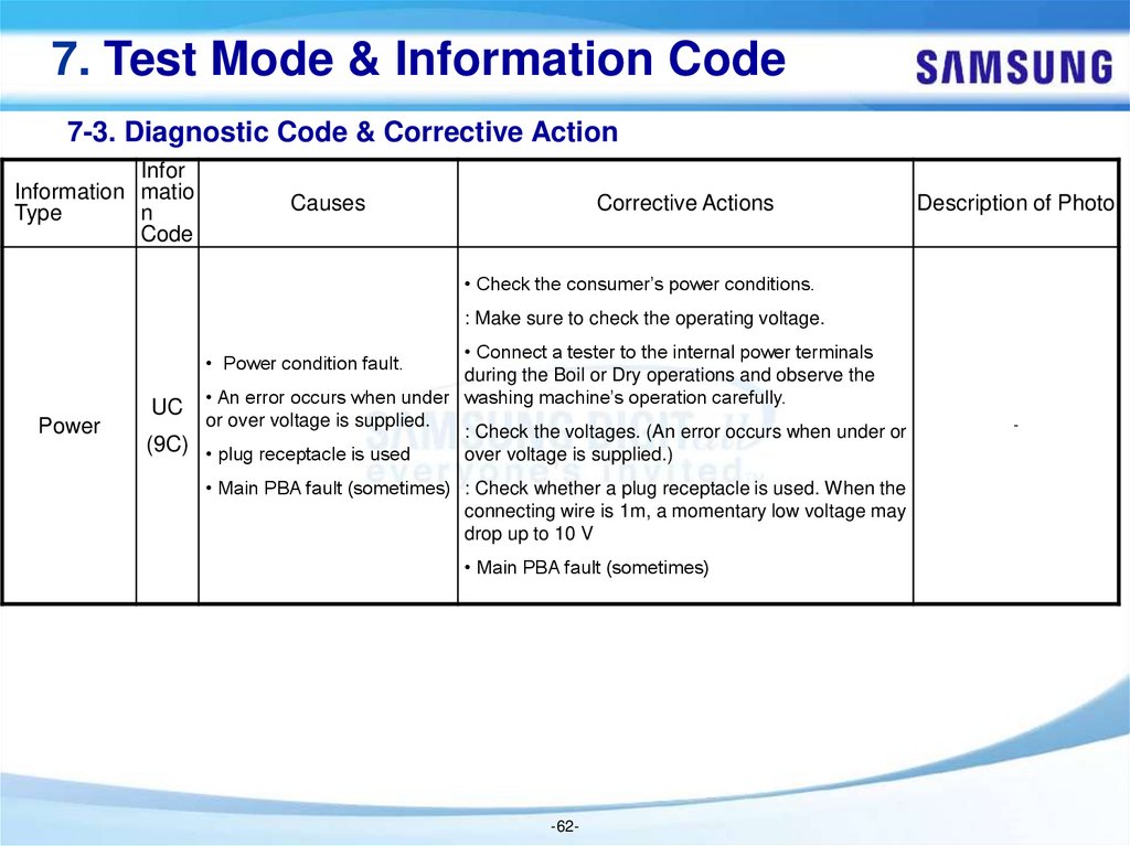
Causes
Corrective Actions
Description of Photo
• Check the consumer’s power conditions.
: Make sure to check the operating voltage.
• Connect a tester to the internal power terminals
during the Boil or Dry operations and observe the
UC • An error occurs when under washing machine’s operation carefully.
or over voltage is supplied.
: Check the voltages. (An error occurs when under or
(9C) • plug receptacle is used
over voltage is supplied.)
• Power condition fault.
Power
• Main PBA fault (sometimes) : Check whether a plug receptacle is used. When the
connecting wire is 1m, a momentary low voltage may
drop up to 10 V
• Main PBA fault (sometimes)
-62-
-
63.
7. Test Mode & Information Code7-3. Diagnostic Code & Corrective Action
Informa Infor
matio
tion
n
Type
Code
Causes
Corrective Actions
Description of Photo
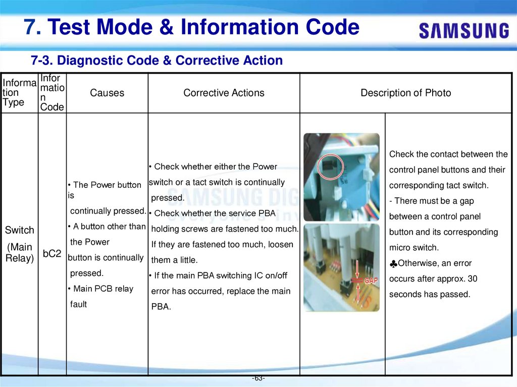
Check the contact between the
• Check whether either the Power
• The Power button switch or a tact switch is continually
is
pressed.
continually pressed. • Check whether the service PBA
Switch
• A button other than holding screws are fastened too much.
the Power
If they are fastened too much, loosen
(Main
bC2
button is continually them a little.
Relay)
control panel buttons and their
corresponding tact switch.
- There must be a gap
between a control panel
button and its corresponding
micro switch.
♣Otherwise, an error
pressed.
• If the main PBA switching IC on/off
occurs after approx. 30
• Main PCB relay
error has occurred, replace the main
seconds has passed.
fault
PBA.
-63-
64.
7. Test Mode & Information Code7-3. Diagnostic Code & Corrective Action
Infor
Informati matio
on Type n
Code
Causes
Corrective Actions
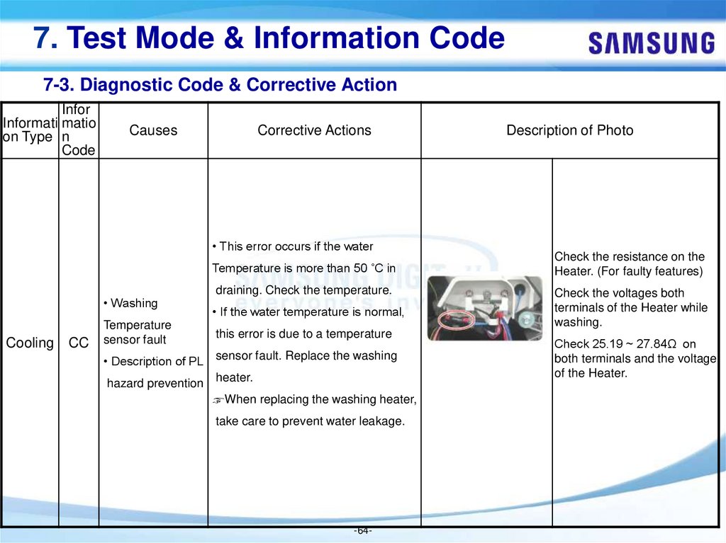
• This error occurs if the water
Temperature is more than 50 ˚C in
• Washing
Cooling
CC
draining. Check the temperature.
• If the water temperature is normal,
Temperature
sensor fault
this error is due to a temperature
• Description of PL
sensor fault. Replace the washing
hazard prevention heater.
☞When replacing the washing heater,
take care to prevent water leakage.
-64-
Description of Photo
Check the resistance on the
Heater. (For faulty features)
Check the voltages both
terminals of the Heater while
washing.
Check 25.19 ~ 27.84Ω on
both terminals and the voltage
of the Heater.
65.
7. Test Mode & Information Code7-3. Diagnostic Code & Corrective Action
Informa Infor
matio
tion
n
Type
Code
Causes
Corrective Actions
Description of Photo
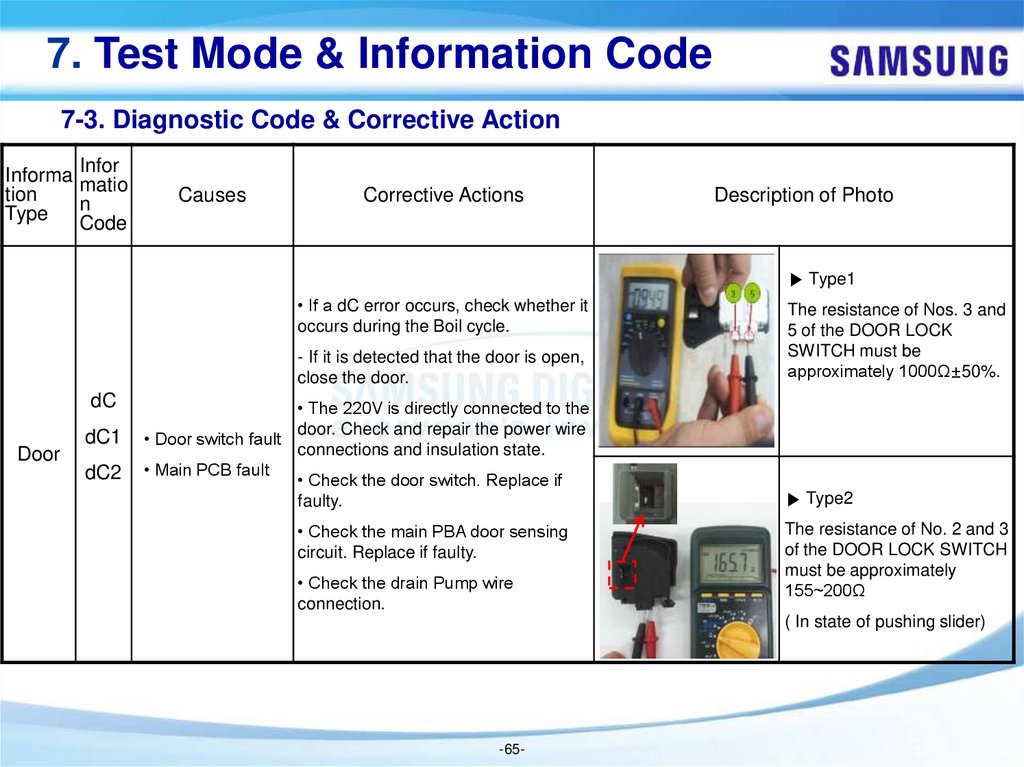
▶ Type1
• If a dC error occurs, check whether it
occurs during the Boil cycle.
- If it is detected that the door is open,
close the door.
dC
Door
dC1
dC2
• The 220V is directly connected to the
door. Check and repair the power wire
• Door switch fault
connections and insulation state.
• Main PCB fault
• Check the door switch. Replace if
faulty.
• Check the main PBA door sensing
circuit. Replace if faulty.
• Check the drain Pump wire
connection.
The resistance of Nos. 3 and
5 of the DOOR LOCK
SWITCH must be
approximately 1000Ω±50%.
▶ Type2
The resistance of No. 2 and 3
of the DOOR LOCK SWITCH
must be approximately
155~200Ω
( In state of pushing slider)
-65-
66.
7. Test Mode & Information Code7-3. Diagnostic Code & Corrective Action
Informa Inform
tion
ation
Type
Code
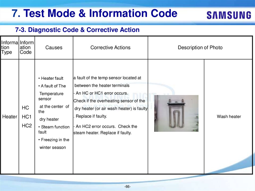
HC
Heater HC1
HC2
Causes
Corrective Actions
• Heater fault
a fault of the temp sensor located at
• A fault of The
between the heater terminals
Temperature
sensor
- An HC or HC1 error occurs.
at the center of
the
dry heater (or air wash heater) is faulty
dry heater
Description of Photo
Check if the overheating sensor of the
. Replace if faulty.
Wash heater
• Steam function - An HC2 error occurs. Check the
fault
steam heater. Replace if faulty.
• Freezing in the
winter season
-66-
67.
7. Test Mode & Information Code7-3. Diagnostic Code & Corrective Action
Infor
Informatio matio
n Type
n
Code
Causes
Corrective Actions
Description of Photo
• Check for any
leakage.
• Foreign material
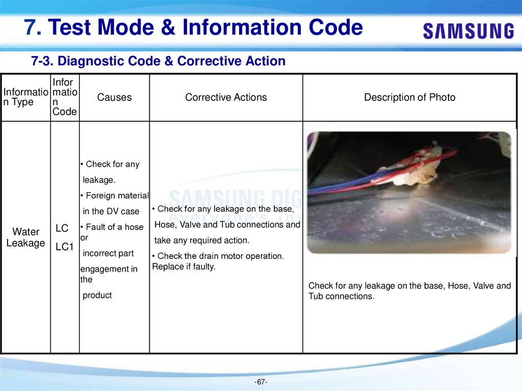
Water
Leakage
LC
LC1
in the DV case
• Check for any leakage on the base,
• Fault of a hose
or
Hose, Valve and Tub connections and
incorrect part
• Check the drain motor operation.
Replace if faulty.
engagement in
the
take any required action.
Check for any leakage on the base, Hose, Valve and
Tub connections.
product
-67-
68.
7. Test Mode & Information Code7-3. Diagnostic Code & Corrective Action
Infor
Informati matio
on Type n
Code
Causes
Corrective Actions
Description of Photo
• If the water level sensor has a functional error,
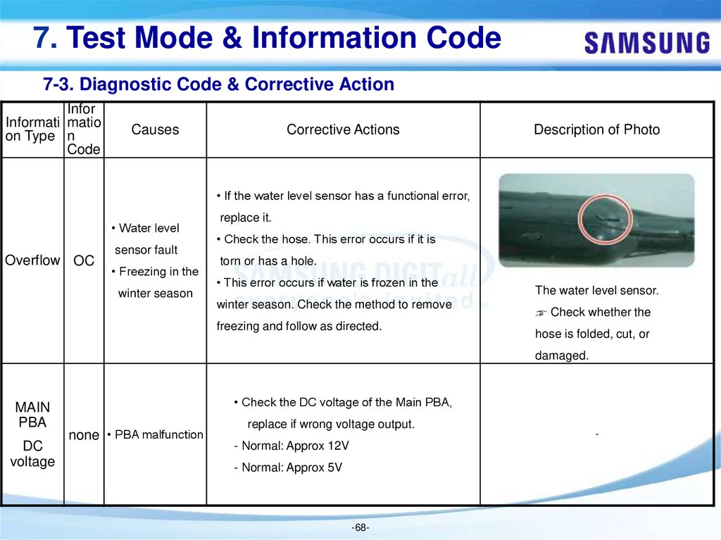
• Water level
Overflow OC
sensor fault
• Freezing in the
winter season
replace it.
• Check the hose. This error occurs if it is
torn or has a hole.
• This error occurs if water is frozen in the
winter season. Check the method to remove
freezing and follow as directed.
The water level sensor.
☞ Check whether the
hose is folded, cut, or
damaged.
MAIN
PBA
DC
voltage
• Check the DC voltage of the Main PBA,
none • PBA malfunction
replace if wrong voltage output.
- Normal: Approx 12V
- Normal: Approx 5V
-68-
-
69.
7. Test Mode & Information Code7-3. Diagnostic Code & Corrective Action
Infor
Information matio
Type
n
Code
Causes
Corrective Actions
• Washing temperature sensor
• Check the connections for the washing heater
fault
temperature sensor connector.
• Dry temperature sensor fault
• If the washing heater temperature sensor has
tC1 • Faulty and incorrect
Temperature tC2
Sensor
tC3
tC4
Description of Photo
a functional error, replace it.
connections of the dry
- A tC1 error occurs.
condensing sensor
• Check the connections for the dry heater
• Main PCB fault
temperature sensor connector.
• Freezing in the winter
season
• If the dry heater temperature sensor has a
• IPM temperature is
abnormally high.
- A tC2 error occurs.
functional error, replace it.
-69-
-
70.
7. Test Mode & Information Code7-3. Diagnostic Code & Corrective Action
Infor
Information matio
Type
n
Code
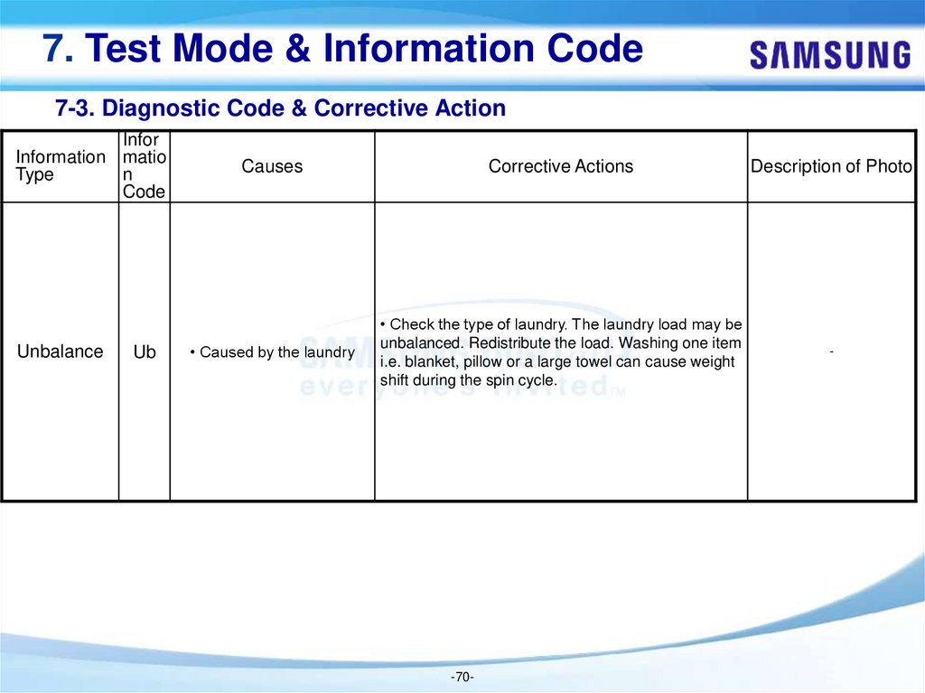
Unbalance
Ub
Causes
Corrective Actions
Description of Photo
• Caused by the laundry
• Check the type of laundry. The laundry load may be
unbalanced. Redistribute the load. Washing one item
i.e. blanket, pillow or a large towel can cause weight
shift during the spin cycle.
-
-70-
71.
7. Test Mode & Information Code7-3. Diagnostic Code & Corrective Action
Infor
Information matio
Type
n
Code
Causes
Corrective Actions
Description of Photo
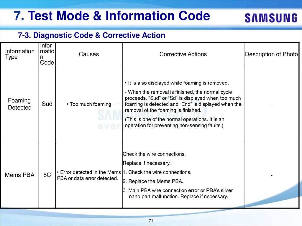
• It is also displayed while foaming is removed.
Foaming
Detected
Sud
• Too much foaming
- When the removal is finished, the normal cycle
proceeds. “Sud” or “Sd” is displayed when too much
foaming is detected and “End” is displayed when the
removal of the foaming is finished.
-
(This is one of the normal operations. It is an
operation for preventing non-sensing faults.)
Check the wire connections.
Replace if necessary.
Mems PBA
8C
• Error detected in the Mems 1. Check the wire connections.
PBA or data error detected.
2. Replace the Mems PBA.
3. Main PBA wire connection error or PBA’s silver
nano part malfunction. Replace if necessary.
-71-
-
72.
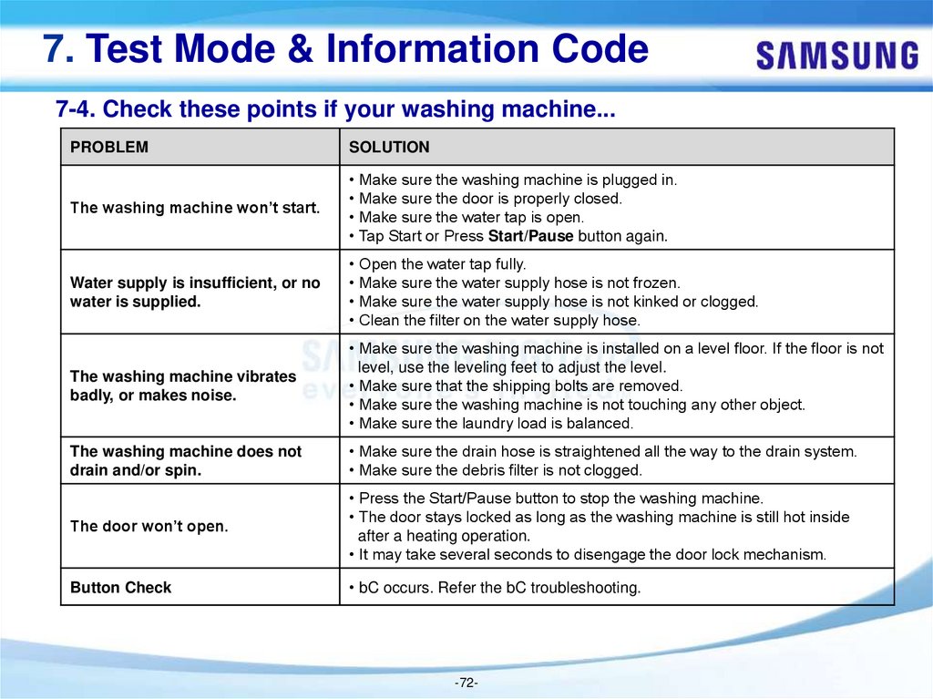
7. Test Mode & Information Code7-4. Check these points if your washing machine...
PROBLEM
SOLUTION
The washing machine won’t start.
• Make sure the washing machine is plugged in.
• Make sure the door is properly closed.
• Make sure the water tap is open.
• Tap Start or Press Start/Pause button again.
Water supply is insufficient, or no
water is supplied.
• Open the water tap fully.
• Make sure the water supply hose is not frozen.
• Make sure the water supply hose is not kinked or clogged.
• Clean the filter on the water supply hose.
The washing machine vibrates
badly, or makes noise.
• Make sure the washing machine is installed on a level floor. If the floor is not
level, use the leveling feet to adjust the level.
• Make sure that the shipping bolts are removed.
• Make sure the washing machine is not touching any other object.
• Make sure the laundry load is balanced.
The washing machine does not
drain and/or spin.
• Make sure the drain hose is straightened all the way to the drain system.
• Make sure the debris filter is not clogged.
The door won’t open.
• Press the Start/Pause button to stop the washing machine.
• The door stays locked as long as the washing machine is still hot inside
after a heating operation.
• It may take several seconds to disengage the door lock mechanism.
Button Check
• bC occurs. Refer the bC troubleshooting.
-72-
73.
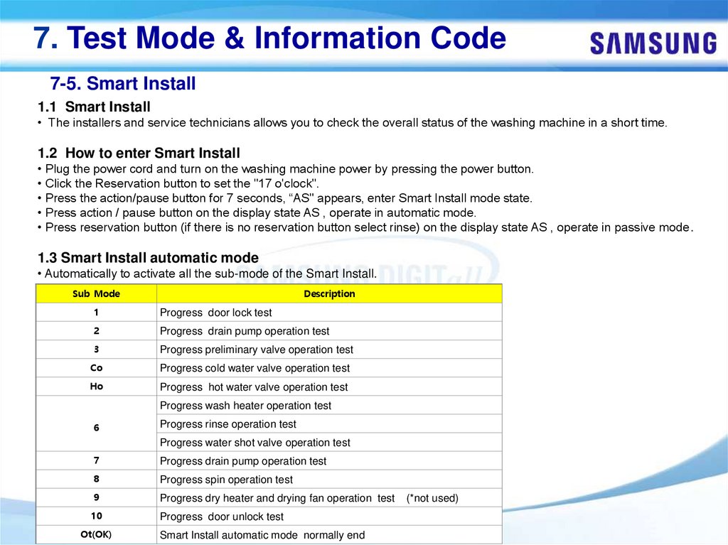
7. Test Mode & Information Code7-5. Smart Install
1.1 Smart Install
• The installers and service technicians allows you to check the overall status of the washing machine in a short time.
1.2 How to enter Smart Install
• Plug the power cord and turn on the washing machine power by pressing the power button.
• Click the Reservation button to set the "17 o'clock".
• Press the action/pause button for 7 seconds, “AS" appears, enter Smart Install mode state.
• Press action / pause button on the display state AS , operate in automatic mode.
• Press reservation button (if there is no reservation button select rinse) on the display state AS , operate in passive mode.
1.3 Smart Install automatic mode
• Automatically to activate all the sub-mode of the Smart Install.
Sub Mode
Description
1
Progress door lock test
2
Progress drain pump operation test
3
Progress preliminary valve operation test
Co
Progress cold water valve operation test
Ho
Progress hot water valve operation test
Progress wash heater operation test
6
Progress rinse operation test
Progress water shot valve operation test
7
Progress drain pump operation test
8
Progress spin operation test
9
Progress dry heater and drying fan operation test
10
Progress door unlock test
Ot(OK)
-73Smart Install automatic mode normally end
(*not used)
74.
7. Test Mode & Information Code7-5. Smart Install
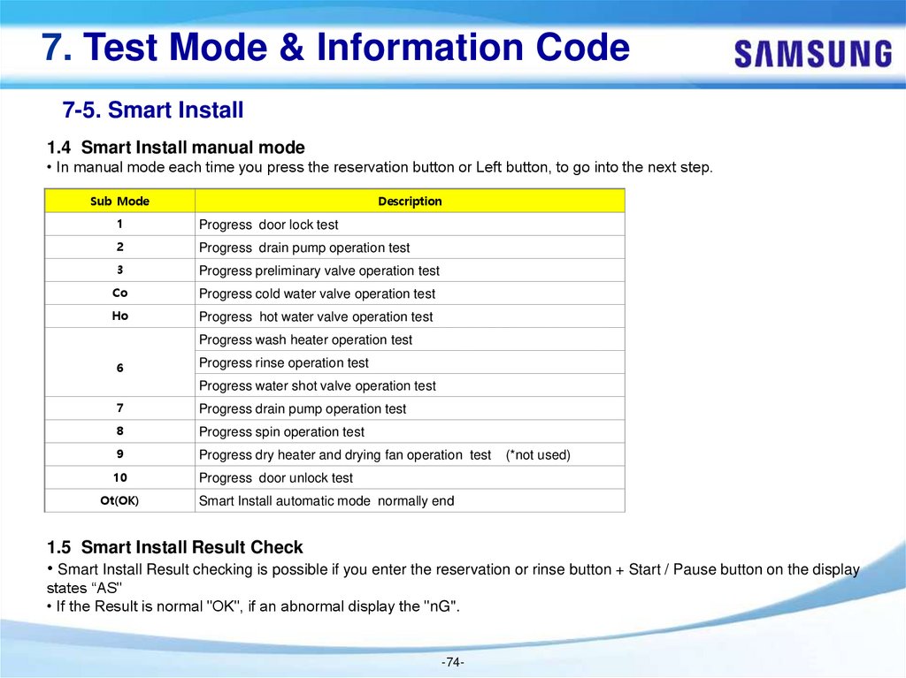
1.4 Smart Install manual mode
• In manual mode each time you press the reservation button or Left button, to go into the next step.
Sub Mode
Description
1
Progress door lock test
2
Progress drain pump operation test
3
Progress preliminary valve operation test
Co
Progress cold water valve operation test
Ho
Progress hot water valve operation test
Progress wash heater operation test
6
Progress rinse operation test
Progress water shot valve operation test
7
Progress drain pump operation test
8
Progress spin operation test
9
Progress dry heater and drying fan operation test
10
Progress door unlock test
Ot(OK)
(*not used)
Smart Install automatic mode normally end
1.5 Smart Install Result Check
• Smart Install Result checking is possible if you enter the reservation or rinse button + Start / Pause button on the display
states “AS"
• If the Result is normal "OK", if an abnormal display the "nG".
-74-
75.
7. Test Mode & Information Code7-5. Smart Install
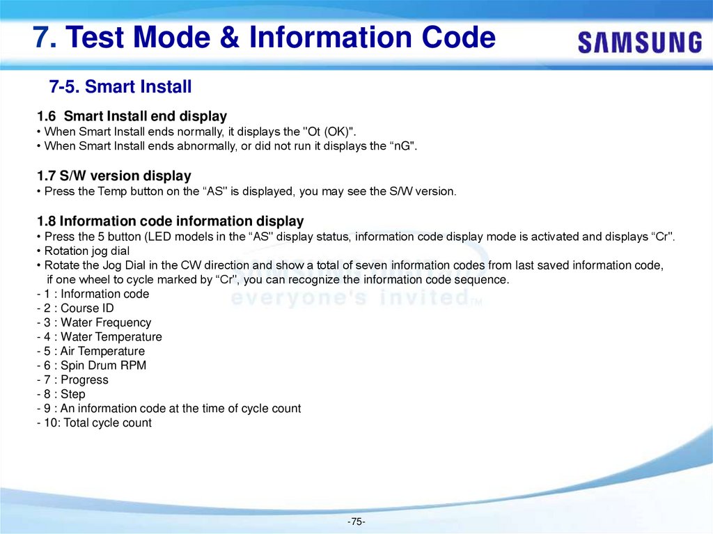
1.6 Smart Install end display
• When Smart Install ends normally, it displays the "Ot (OK)".
• When Smart Install ends abnormally, or did not run it displays the “nG".
1.7 S/W version display
• Press the Temp button on the “AS" is displayed, you may see the S/W version.
1.8 Information code information display
• Press the 5 button (LED models in the “AS" display status, information code display mode is activated and displays “Cr".
• Rotation jog dial
• Rotate the Jog Dial in the CW direction and show a total of seven information codes from last saved information code,
if one wheel to cycle marked by “Cr", you can recognize the information code sequence.
- 1 : Information code
- 2 : Course ID
- 3 : Water Frequency
- 4 : Water Temperature
- 5 : Air Temperature
- 6 : Spin Drum RPM
- 7 : Progress
- 8 : Step
- 9 : An information code at the time of cycle count
- 10: Total cycle count
-75-
76.
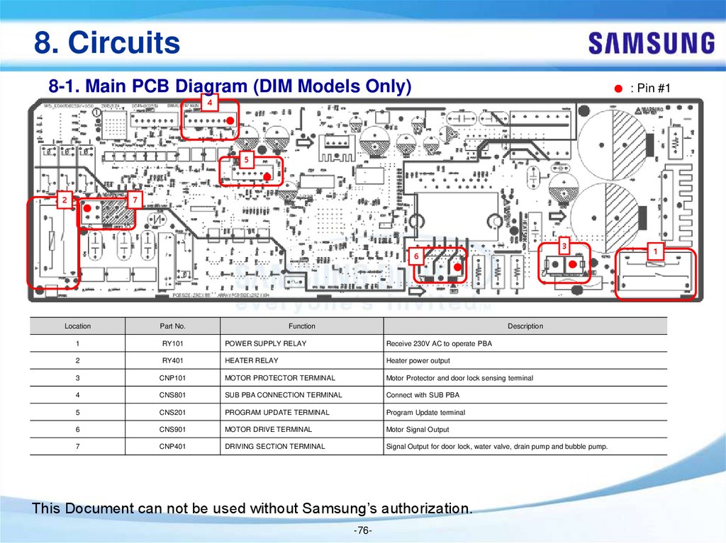
8. Circuits8-1. Main PCB Diagram (DIM Models Only)
: Pin #1
4
5
2
7
3
6
Location
Part No.
Function
Description
1
RY101
POWER SUPPLY RELAY
Receive 230V AC to operate PBA
2
RY401
HEATER RELAY
Heater power output
3
CNP101
MOTOR PROTECTOR TERMINAL
Motor Protector and door lock sensing terminal
4
CNS801
SUB PBA CONNECTION TERMINAL
Connect with SUB PBA
5
CNS201
PROGRAM UPDATE TERMINAL
Program Update terminal
6
CNS901
MOTOR DRIVE TERMINAL
Motor Signal Output
7
CNP401
DRIVING SECTION TERMINAL
Signal Output for door lock, water valve, drain pump and bubble pump.
This Document can not be used without Samsung’s authorization.
-76-
1
77.
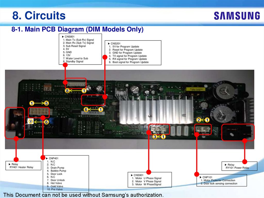
8. Circuits8-1. Main PCB Diagram (DIM Models Only)
▶ CNS801
1. Main Tx (Sub Rx) Signal
2. Main Rx (Sub Tx) Signal
3. Sub Reset Signal
4. 5V
5. GND
6. 13V
7. Water Level to Sub
8. Standby Signal
8
1
▶ CNS201
1. 5V for Program Update
2. Reset for Program Update
3. GND for Program Update
4. TX signal for Program Update
5. RX signal for Program Update
6. Boot signal for Program Update
1
5
6
1
2
6
3
▶ Relay
RY401 Heater Relay
▶ CNP401
1. N.C
2. N.C
3. Drain Pump
4. Bubble Pump
5. Door Lock
6. N.C
7. Door Unlock
8. Hot Valve
9. Cold Valve
10. Pre Valve
1
1
▶ Relay
RY101 Power Relay
▶ CNS901
1. Motor U Phase Signal
2. Motor V Phase Signal
3. Motor W PhaseSignal
This Document can not be used without Samsung’s authorization.
▶ CNP101
1. Motor Protector Connection
2. Door lock sensing connection
78.
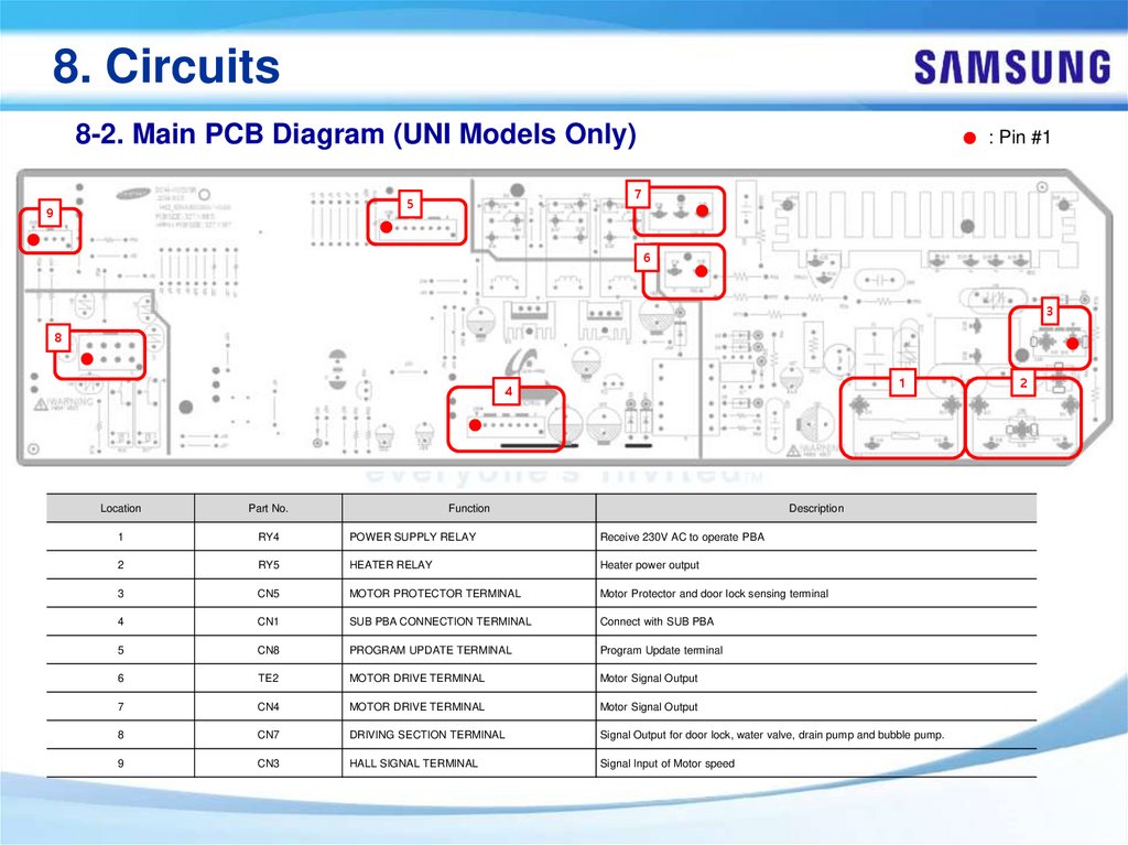
8. Circuits8-2. Main PCB Diagram (UNI Models Only)
7
5
9
: Pin #1
6
3
8
1
4
Location
Part No.
Function
Description
1
RY4
POWER SUPPLY RELAY
Receive 230V AC to operate PBA
2
RY5
HEATER RELAY
Heater power output
3
CN5
MOTOR PROTECTOR TERMINAL
Motor Protector and door lock sensing terminal
4
CN1
SUB PBA CONNECTION TERMINAL
Connect with SUB PBA
5
CN8
PROGRAM UPDATE TERMINAL
Program Update terminal
6
TE2
MOTOR DRIVE TERMINAL
Motor Signal Output
7
CN4
MOTOR DRIVE TERMINAL
Motor Signal Output
8
CN7
DRIVING SECTION TERMINAL
Signal Output for door lock, water valve, drain pump and bubble pump.
9
CN3
HALL SIGNAL TERMINAL
Signal Input of Motor speed
2
79.
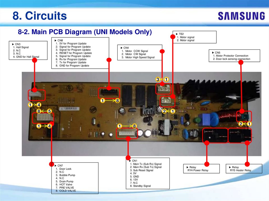
8. Circuits8-2. Main PCB Diagram (UNI Models Only)
▶ CN8
1. 5V for Program Update
2. Signal for Program Update
3. Signal for Program Update
4. RESET for Program Update
5. Signal for Program Update
6. Rx for Program Update
7. Tx for Program Update
8. GND for Program Update
▶ CN3
1. Hall Signal
2. N.C
3. N.C
4. GND for Hall Signal
▶ TE2
1. Motor signal
2. Motor signal
▶ CN4
1. Motor CCW Signal
2. Motor CW Signal
3. Motor High Speed Signal
▶ CN5
1. Motor Protector Connection
2. Door lock sensing connection
3
1
1
4
8
5
1
4
1
8
2
1
▶ CN7
1. Door Lock
2. N.C
3. Bubble Pump
4. N.C
5. Drain Pump
6. HOT Valve
7. PRE VALVE
8. COLD VALVE
1
2
8
▶ CN1
1. Main Tx (Sub Rx) Signal
2. Main Rx (Sub Tx) Signal
3. Sub Reset Signal
4. 5V
5. GND
6. 13V
7. N.C
8. Standby Signal
▶ Relay
RY4 Power Relay
1
▶ Relay
RY5 Heater Relay
80.
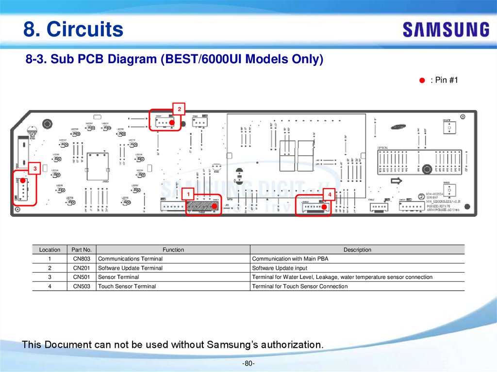
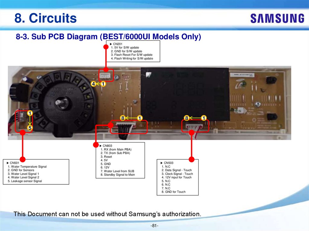
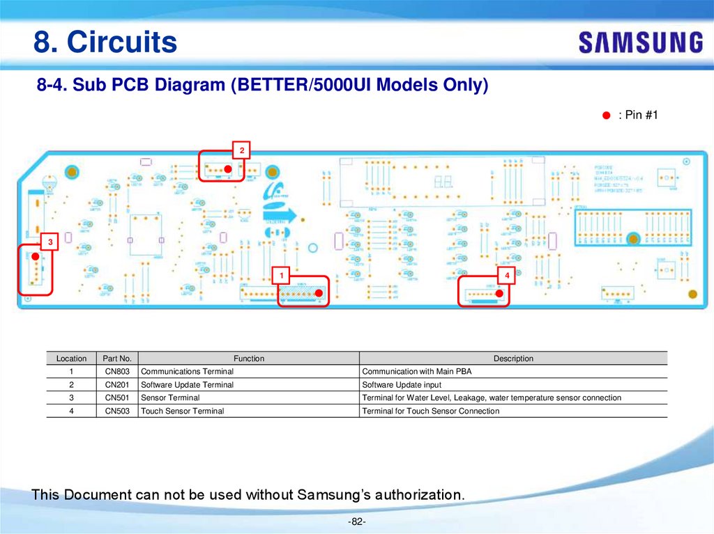
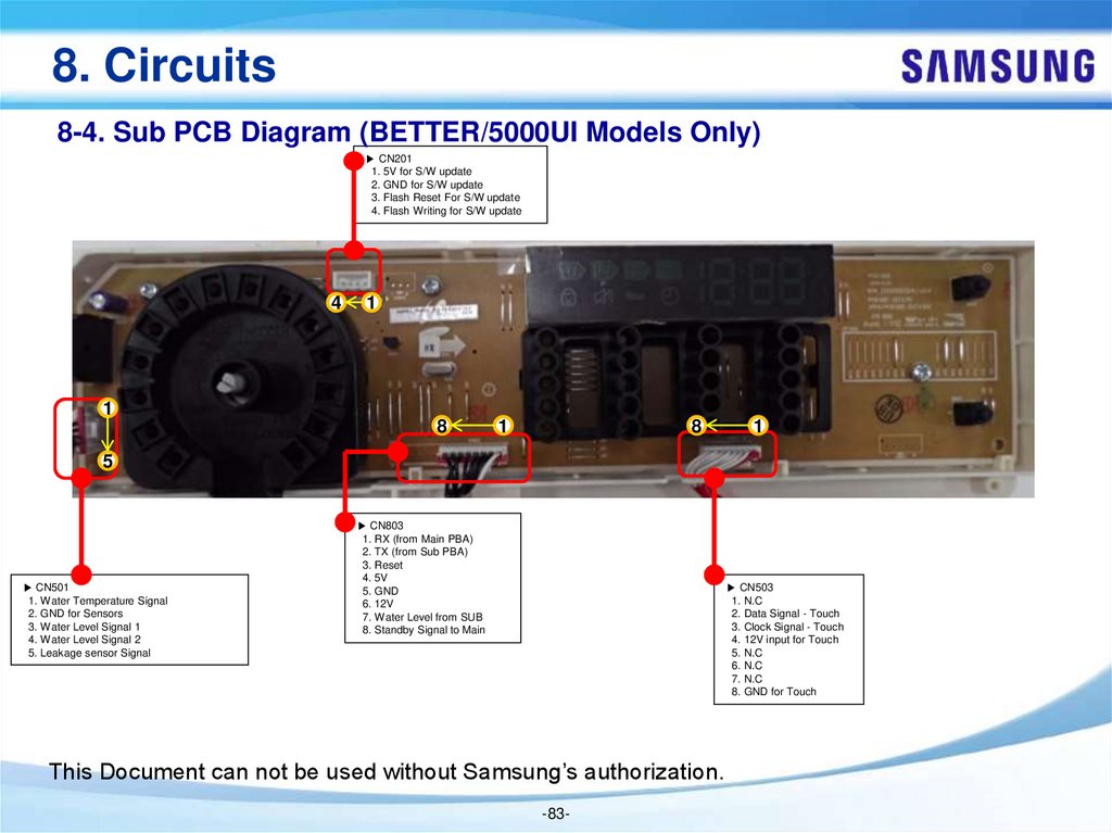
8. Circuits8-3. Sub PCB Diagram (BEST/6000UI Models Only)
: Pin #1
2
3
1
4
Location
Part No.
1
CN803
Communications Terminal
Function
Communication with Main PBA
Description
2
CN201
Software Update Terminal
Software Update input
3
CN501
Sensor Terminal
Terminal for Water Level, Leakage, water temperature sensor connection
4
CN503
Touch Sensor Terminal
Terminal for Touch Sensor Connection
This Document can not be used without Samsung’s authorization.
-80-
81.
8. Circuits8-3. Sub PCB Diagram (BEST/6000UI Models Only)
▶ CN201
1. 5V for S/W update
2. GND for S/W update
3. Flash Reset For S/W update
4. Flash Writing for S/W update
4
1
1
8
1
8
5
▶ CN501
1. Water Temperature Signal
2. GND for Sensors
3. Water Level Signal 1
4. Water Level Signal 2
5. Leakage sensor Signal
▶ CN803
1. RX (from Main PBA)
2. TX (from Sub PBA)
3. Reset
4. 5V
5. GND
6. 12V
7. Water Level from SUB
8. Standby Signal to Main
▶ CN503
1. N.C
2. Data Signal - Touch
3. Clock Signal - Touch
4. 12V input for Touch
5. N.C
6. N.C
7. N.C
8. GND for Touch
This Document can not be used without Samsung’s authorization.
-81-
1
82.
8. Circuits8-4. Sub PCB Diagram (BETTER/5000UI Models Only)
: Pin #1
2
3
1
4
Location
Part No.
1
CN803
Communications Terminal
Function
Communication with Main PBA
Description
2
CN201
Software Update Terminal
Software Update input
3
CN501
Sensor Terminal
Terminal for Water Level, Leakage, water temperature sensor connection
4
CN503
Touch Sensor Terminal
Terminal for Touch Sensor Connection
This Document can not be used without Samsung’s authorization.
-82-
83.
8. Circuits8-4. Sub PCB Diagram (BETTER/5000UI Models Only)
▶ CN201
1. 5V for S/W update
2. GND for S/W update
3. Flash Reset For S/W update
4. Flash Writing for S/W update
4
1
1
8
1
8
1
5
▶ CN501
1. Water Temperature Signal
2. GND for Sensors
3. Water Level Signal 1
4. Water Level Signal 2
5. Leakage sensor Signal
▶ CN803
1. RX (from Main PBA)
2. TX (from Sub PBA)
3. Reset
4. 5V
5. GND
6. 12V
7. Water Level from SUB
8. Standby Signal to Main
▶ CN503
1. N.C
2. Data Signal - Touch
3. Clock Signal - Touch
4. 12V input for Touch
5. N.C
6. N.C
7. N.C
8. GND for Touch
This Document can not be used without Samsung’s authorization.
-83-
84.
8. Circuits8-5. Wiring Diagram (DIM Models only)
This Document can not be used without Samsung’s authorization.
-84-
85.
8. Circuits8-6. Wiring Diagram (UNI Models only)
This Document can not be used without Samsung’s authorization.
-85-
86.
9. Reference Information9-1. Components Check
Drain Motor
BLDC/UNI Motor
Wash Heater
Unplug the connector and
read resistance at the terminals on
Motor Power Any Terminal 2pin Check
4.8~4.95Φ (UNI Motor)
<Heater>
Drain Pump
5.0~6.1Φ (BLDC Motor)
Read resistance at the squares
: Should be 25.19 to 27.84Ω
: Should be 225.8 to 229.8 Ω
-86-
87.
9. Reference Information9-1. Components Check
SWITCH DOOR LOCK
Type1
Water Level Sensor
Type2
Measure resistance between Measure resistance between
the
the
center terminal (Common)
and each
Measure Frequency at
center terminal (Common)
and each
two terminals of each end
of the outer two terminals
: Should be approx. 25.0KHz
: Should be 1000Ω±50%
: Should be 155~200Ω
(with no load)
( In state of pushing slider)
( In state of pushing slider)
of the outer two terminals
Water Valve
-87-
Slip out the connectors and
Measure resistance
between 2 terminals:
Should be 3.6 to 4.4 kΩ
at each Solenoid
88.
9. Reference Information9-2. Nomenclature
WW
90
J
5
Type
Capacity
PJT year
Product Name (Series)
Code Content Code Content Code Year Code
WW Washer
WD Combo
12
12.5
J
2015
9
Design
Premium LC
D
4
5
5
Feature1
Feature2 (feature variable)
Feature3 (display,Wifi,depth)
Super Sp
Code RPM
eed
7
1600
Motor Code Bubble
Uni
0
Steam
A.Hose L.Sensor C.Heater Code
X
X
UI
0
Full Touch LCD
_9000H
D
Door Design
Cycle
Wifi Type Code
QTY
14
A
STD
A
Door Color & Type
(Add door)
Crystal Blue
E
Body & Display Color
Jog
Blue
Code Body
W
12
12
K
2016
8
Best LCD
6
1600
DIT
1
X
X
9
Color LCD_8000
14
H
STD
B
Crystal Gloss '15 (Blue)
Blue
S
11
11.5
M
2017
7
Premium LE
D
5
1400
Uni
2
X
8
7000 '15
14
STD
C
Crystal Gloss '15 (White)
White
X
White
U
Region
Display
Code
Region
Black or LC
D
EU
U.K
Black or LC
Silver
D
Black or LC
Inox
D
Black or LC
Black
D
Black or LC
Gold
D
LP
RUSSIA
EF
FRANCE
SA
AUSTRALIA
11
11
6
Best LED
4
1400
DIT
3
X
X
7
6000 '15
14
STD
D
Crystal Gloss '16 (White)
White
K
10
10.5
5
Better LED
X
3
1200
Uni
4
X
X
X
6
6000 '15
14
X
STD
E
Crystal Gloss '16 (Grey)
Black
G
10
10.2
4
Good LED
X
2
1200
DIT
5
X
X
X
X
5
5000 '15
14
X
STD
F
Crystal Gloss '16 (Blue)
Blue
A
White
Silver
EO
POLAND
10
10.1
3
Basic LED
X
1
1000
Uni
6
X
X
X
X
4
4000 '15_best
14
X
STD
G
Crystal Gloss '16 (Dim Grey)
Black
B
Silver
Silver
EG
GERMANY
0
1000
DIT
7
X
X
X
X
X
3
4000 '15
12
X
STD
H
Crystal Gloss '16 (Navy)
Blue
C
Inox
Silver
PORTUGAL
X
EP
8
X
X
2
3000 '15
10
X
STD
I
Crystal Gloss (White)
White
D
Black
Silver
10
10
95
9.5
90
9
1
7000 '15
14
slim
J
Crystal Gloss (Blue)
Blue
E
Gold
Silver
EC
SPAIN
85
8.5
A
6000 touch '17
15
slim
K
Crystal Gloss (Dim Grey)
Black
F
White
White
LE
ROMANIA
80
8
B
6000 touch '17
15
X
slim
L
Crystal Gloss (Navy)
Blue
H
Silver
White
UA
UKRAINE
76
7.6
C
5000 touch '17
14
X
slim
M
Basic (White)
White
I
Inox
White
WS
SWAZILAN
D
75
7.5
D
4000 touch '17
14
X
slim
N
Basic (Blue)
Blue
J
Black
White
LO
TUNISIA
70
7
E
6000 '15
14
slim
O
Add Wash Crystal Blue
Blue
L
Gold
White
EN
NETHERLA
NDS
65
6.5
F
6000 '15
14
X
slim
P
62
6.2
G
5000 '15
14
X
slim
Q
60
6
H
4000 '15_best
14
X
slim
R
I
4000 '15
12
X
slim
S
J
3000 '15
10
X
slim
T
U
Add Wash Crystal Gloss '15 (B
lue)
Add Wash Crystal Gloss '15 (
White)
Add Wash Crystal Gloss '16 (
White)
Add Wash Crystal Gloss '16 (G
rey)
Add Wash Crystal Gloss '16 (B
lue)
Add Wash Crystal Gloss '16 (D
im Grey)
Add Wash Crystal Gloss '16 (N
avy)
Add Wash Crystal Gloss (Whit
W
e)
V
-88-
Blue
ET
ITALY
White
AH
TURKEY
MF
MOROCCO
Blue
LV
GREECE
Black
ZE
CZECH
White
Black
Blue
White
X
Add Wash Crystal Gloss (Blue)
Blue
Y
Add Wash Basic (White)
White
Z
Add Wash Basic (Blue)
Blue
0
Basic (Chrome)
Black
89.
9. Reference Information9-3. Water Flow
Path #1
Path #2
Path #3
Pre Wash
Main Wash
Main Wash
-89-
Path#1
Path#2
Path#3
MAIN(H)
PRE WASH
MAIN(C)
90.
9. Reference Information9-4. How it works
Water-Level sensor
Structure
△x
Ferrite Core
<inside structure>
System
Operation
Water level rise → Diaphragm change by air pressure
→ Ferrite's position change → Change of L value
→ Frequency change
-90-
91.
9. Reference Information9-5. Terminology
1. Drain Pump
The pump that drains the water from the washing machine
generated while the washing machine is running
2. Heater
The heater is located on the tub inside the washing machine. It
heats the water to increase wash efficiency.
3. Door Lock Switch
Detects whether the door of the washing machine is open or
closed. If the door is open while the washing machine is
running the cycle is temporary stopped.
-91-
92.
- The End -Thank you.
-92-