


 Электроника
Похожие презентации:


")


")
Calculation methods of the branched DC linear electric circuits. Part II
1.
Annotation for the lectureCalculation methods of the branched DC linear electric circuits
Part II
In the lecture, using the example of a circuit, the derivation of the equation for
calculating the voltage by the method of two nodes is given, calculation formulas are
given, including the formulas for calculating the currents in the branches of the circuit.
The essence of Thevenin's theorem and Norton's theorem are explained. It is explained
how the Thevenin’s EMF Eth, the current of the Norton current source JN and the internal
resistance of the equivalent generator Rth are found.
The rules for choosing the signs of the terms in the power balance equation are
considered.
2. Theory of Electrical Circuits for IT specialty
Lecture 4Calculation methods of the branched
DC linear electric circuits
Part II
Senior lecturer of the Department of Radioengineering, Electronics and Telecommunications
Kreslina Svetlana Yuryevna
s.kreslina@iitu.edu.kz
3.
List of references:1 John Bird. Electrical Circuit Theory and Technology – Sixth edition 2017. – 844 p.
2 Fundamentals of Electric Circuits / Charles K. Alexander, Matthew N. O. Sadiku. – 5th edition – 2013.
– 995 p.
3 Introductory Circuit Analysis / Robert L. Boylestad. – 13th edition 2015. – 1224 p.
Internet sources:
4 Kazakhstan National Electronic Library http://kazneb.kz/
5 Online course https://www.coursera.org/learn/linear-circuits-dcanalysis
6 Online course https://www.coursera.org/learn/linear-circuits-ac-analysis
7 Online course https://www.coursera.org/learn/electrodynamics-solutions-maxwells-equations
8 Free online courses from 140 leading universities in the world https://www.edx.org/
9 https://www.twirpx.com/files/science/tek/toe/?ft=lecture
10 http://www.toehelp.ru/theory/toe/contents.html
11 Publisher-independent global publication citation database and research analytics platform
https://clarivate.com/webofsciencegroup/solutions/web-of-science/
12 National Open University of Russia INTUIT https://www.intuit.ru/
4. Lecture sections:
4.1 Method of two nodes4.2 Thévenin’s and Norton’s theorems
4.3 Power balance
5.
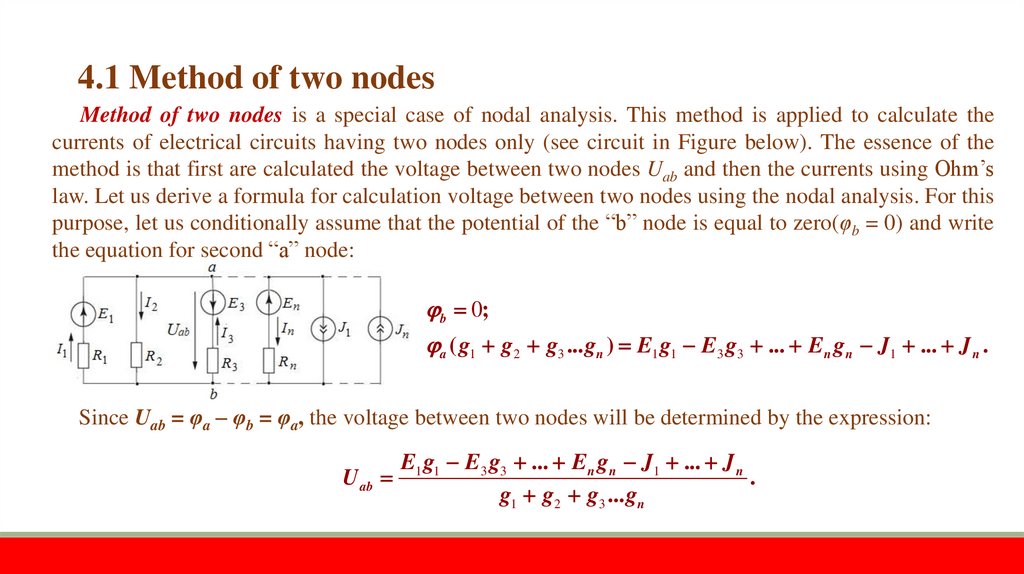
4.1 Method of two nodesMethod of two nodes is a special case of nodal analysis. This method is applied to calculate the
currents of electrical circuits having two nodes only (see circuit in Figure below). The essence of the
method is that first are calculated the voltage between two nodes Uab and then the currents using Ohm’s
law. Let us derive a formula for calculation voltage between two nodes using the nodal analysis. For this
purpose, let us conditionally assume that the potential of the “b” node is equal to zero(φb = 0) and write
the equation for second “a” node:
b 0;
a ( g1 g2 g3 ... gn ) E1 g1 E3 g3 ... En gn J1 ... J n .
Since Uab = φa – φb = φa, the voltage between two nodes will be determined by the expression:
U ab
E1 g1 E3 g3 ... En gn J1 ... J n
.
g1 g2 g3 ... gn
6.
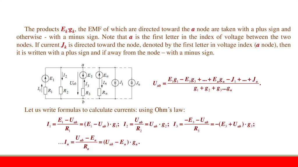
The products Ek‧gk, the EMF of which are directed toward the a node are taken with a plus sign andotherwise - with a minus sign. Note that a is the first letter in the index of voltage between the two
nodes. If current Jk is directed toward the node, denoted by the first letter in voltage index (a node), then
it is written with a plus sign and if away from the node – with a minus sign.
U ab
E1 g1 E3 g3 ... En gn J1 ... J n
.
g1 g2 g3 ... gn
Let us write formulas to calculate currents: using Ohm’s law:
I1
E1 U ab
U
E3 U ab
( E1 U ab ) g1 ; I 2 ab U ab g2 ; I 3
( E3 U ab ) g3 ;
R1
R2
R3
In
U ab En
(U ab En ) gn .
Rn
7.
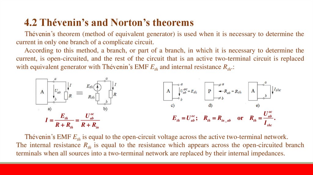
4.2 Thévenin’s and Norton’s theoremsThévenin’s theorem (method of equivalent generator) is used when it is necessary to determine the
current in only one branch of a complicate circuit.
According to this method, a branch, or part of a branch, in which it is necessary to determine the
current, is open-circuited, and the rest of the circuit that is an active two-terminal circuit is replaced
with equivalent generator with Thévenin’s EMF Eth and internal resistance Rth.:
I
oc
ab
Eth
U
R Rth R Rin
Eth U aboc ; Rth Rin _ ab
or
U aboc
Rth
.
I shc
Thévenin’s EMF Eth is equal to the open-circuit voltage across the active two-terminal network.
The internal resistance Rth is equal to the resistance which appears across the open-circuited branch
terminals when all sources into a two-terminal network are replaced by their internal impedances.
8.
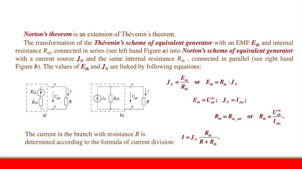
Norton’s theorem is an extension of Thévenin’s theorem.The transformation of the Thévenin’s scheme of equivalent generator with an EMF Eth and internal
resistance Rth, connected in series (see left hand Figure a) into Norton’s scheme of equivalent generator
with a current source JN and the same internal resistance Rth , connected in parallel (see right hand
Figure b). The values of Eth and JN are linked by following equations:
JN
Eth
Rth
or Eth Rth J N
Eth U aboc ; J N I shc ;
Rth Rin _ ab
The current in the branch with resistance R is
determined according to the formula of current division:
I JN
Rth
.
R Rth
or
U aboc
Rth
.
I shc
9.
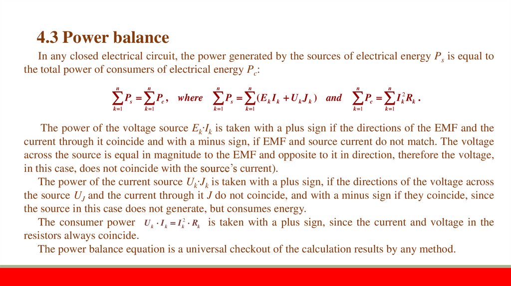
4.3 Power balanceIn any closed electrical circuit, the power generated by the sources of electrical energy Ps is equal to
the total power of consumers of electrical energy Pc:
n
n
n
n
n
n
P P , where P ( E I U J ) and P I R .
k 1
s
k 1
c
k 1
s
k 1
k
k
k
k
k 1
c
k 1
2
k
k
The power of the voltage source Ek‧Ik is taken with a plus sign if the directions of the EMF and the
current through it coincide and with a minus sign, if EMF and source current do not match. The voltage
across the source is equal in magnitude to the EMF and opposite to it in direction, therefore the voltage,
in this case, does not coincide with the source’s current).
The power of the current source Uk‧Jk is taken with a plus sign, if the directions of the voltage across
the source UJ and the current through it J do not coincide, and with a minus sign if they coincide, since
the source in this case does not generate, but consumes energy.
The consumer power U k I k I k2 Rk is taken with a plus sign, since the current and voltage in the
resistors always coincide.
The power balance equation is a universal checkout of the calculation results by any method.
10.
1.2.
3.
4.
5.
6.
7.
8.
9.
Test questions:
Give a formula to determine the voltage between two nodes.
Explain the essence of Thévenin’s theorem.
How to determine the Thévenin’s EMF Eth?
Explain the procedure for determining the Thévenin’s resistance Rth.
Explain the essence of Norton’s theorem.
How to determine the value of the equivalent Norton’s current source JN?
Explain the procedure for making up the power balance equation.
How to calculate the total power of the sources of electrical energy in the circuit?
How to calculate the total electrical power consumption of the circuit?
11.
Thank Youfor your attention