


 Механика
Похожие презентации:


")

Backhoe Loader H200 Level 2 Pt 3 05-2008
1.
Backhoe Loader H200 Level 2 Pt 305-2008
Coventry
2.
Backhoe Loader Level 2* 4 Wheel Steering *
3.
Backhoe Loader Level 24 Wheel Steering Mode Switch – 970/980 models
Located under the side control panel, this switch makes it
possible to select 4 wheel steering, two wheel steering or crab
steering. The switch has three positions:
3
2
1
Position 1: 4 wheel steering.
Position 2: 2 wheel steering.
Position 3: crab steering.
The tab (A) is used to lock the switch in 2 wheel
steer position.
Before under taking any road travel, select two
wheel steer position and place the tab over the
switch to lock it in this position.
A
Any malfunction must be reported to
your local dealer immediately.
Travel at on-road speeds in 4WS mode
can result in loss of control or unexpected
swing-out of the rear end. Travel in crab
mode will prevent the normal negotiation
of bends, corners and intersections.
4.
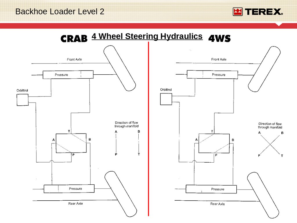
Backhoe Loader Level 24 Wheel Steering
Hydraulics
4 Wheel Steering
Hydraulics
Front Axle
Proximity Switch
Steering Obitrol
Steering Priorty/Unloader Valve
Load Sense Line
Steering Mode Switch –
Instrument Panel
Changeover Valve
Control Unit – Relay
Panel
Proximity Switch
Rear Axle
5.
Backhoe Loader Level 24 Wheel Steering Hydraulics
Changeover Valve Oil Flow –
Wheel Orientation
6.
Backhoe Loader Level 24 Wheel Steering Hydraulics
7.
Backhoe Loader Level 24 Wheel Steering Hydraulic Locations
Rear Axle
Rear Axle Steering Cylinder
Steering Change Over Valve
Steering Proximity Switch
Steering / Priority Valve
Rear Axle
Main Hydraulic Pumps
Loader Valve
Both the front and rear axle have a similar build, with a proximity switch in the centre
position on the steering cylinder on both axles.
8.
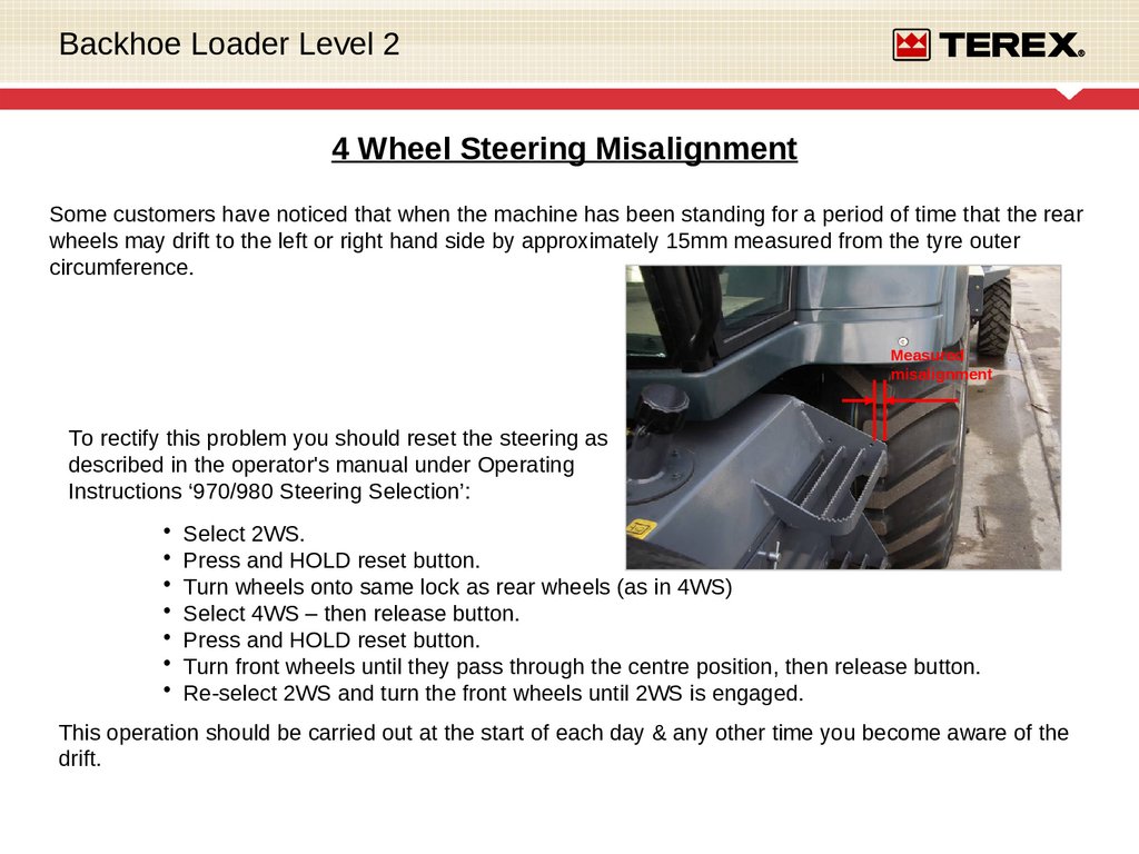
Backhoe Loader Level 24 Wheel Steering Misalignment
Some customers have noticed that when the machine has been standing for a period of time that the rear
wheels may drift to the left or right hand side by approximately 15mm measured from the tyre outer
circumference.
Measured
misalignment
To rectify this problem you should reset the steering as
described in the operator's manual under Operating
Instructions ‘970/980 Steering Selection’:
Select 2WS.
Press and HOLD reset button.
Turn wheels onto same lock as rear wheels (as in 4WS)
Select 4WS – then release button.
Press and HOLD reset button.
Turn front wheels until they pass through the centre position, then release button.
Re-select 2WS and turn the front wheels until 2WS is engaged.
This operation should be carried out at the start of each day & any other time you become aware of the
drift.
9.
Backhoe Loader Level 24 Wheel Steering Misalignment
10.
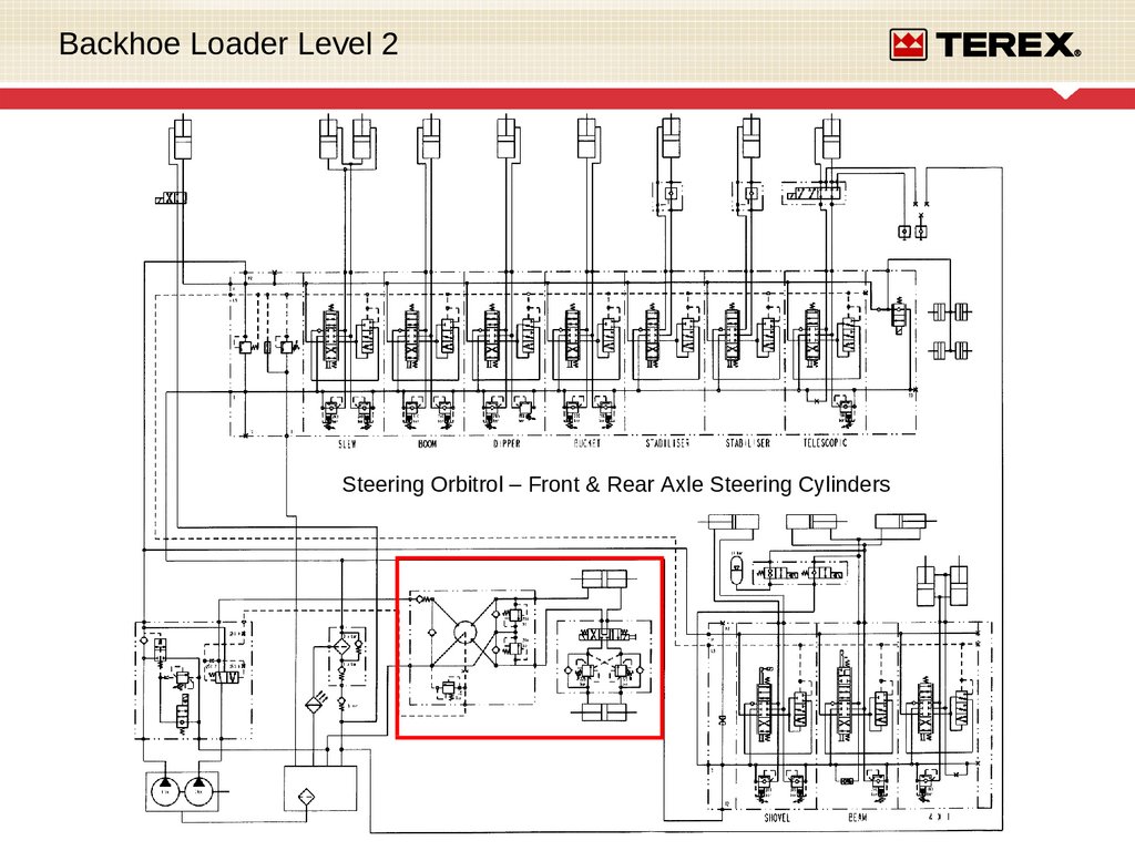
Backhoe Loader Level 2Steering Orbitrol – Front & Rear Axle Steering Cylinders
11.
Backhoe Loader Level 24WS Electrical Schematic
12.
Backhoe Loader Level 2* Servo Controls *
13.
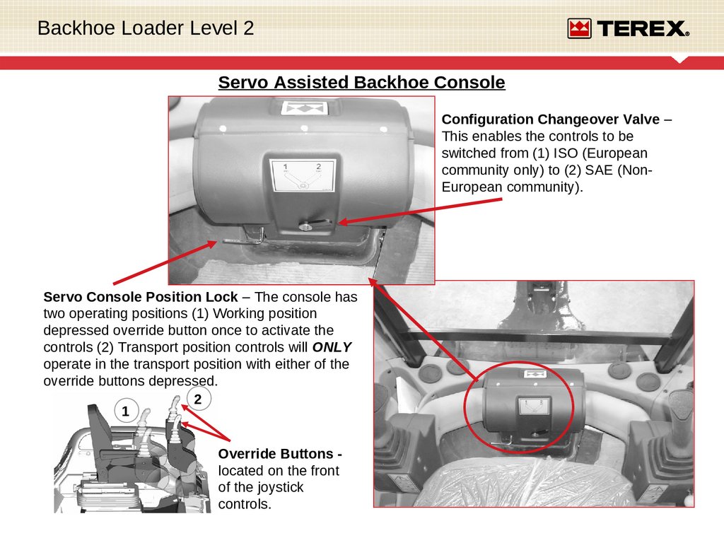
Backhoe Loader Level 2Servo Assisted Backhoe Console
Configuration Changeover Valve –
This enables the controls to be
switched from (1) ISO (European
community only) to (2) SAE (NonEuropean community).
Servo Console Position Lock – The console has
two operating positions (1) Working position
depressed override button once to activate the
controls (2) Transport position controls will ONLY
operate in the transport position with either of the
override buttons depressed.
2
1
Override Buttons located on the front
of the joystick
controls.
14.
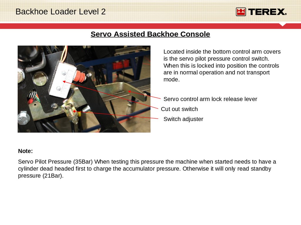
Backhoe Loader Level 2Servo Assisted Backhoe Console
Located inside the bottom control arm covers
is the servo pilot pressure control switch.
When this is locked into position the controls
are in normal operation and not transport
mode.
Servo control arm lock release lever
Cut out switch
Switch adjuster
Note:
Servo Pilot Pressure (35Bar) When testing this pressure the machine when started needs to have a
cylinder dead headed first to charge the accumulator pressure. Otherwise it will only read standby
pressure (21Bar).
15.
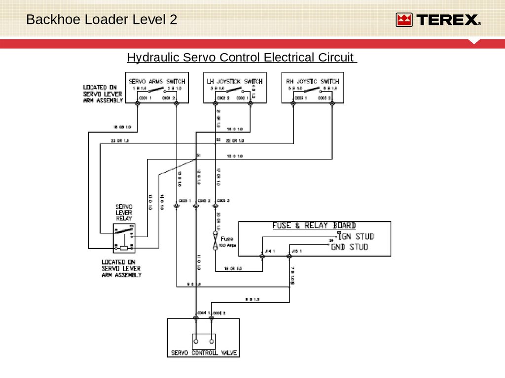
Backhoe Loader Level 2Hydraulic Servo Control Electrical Circuit
16.
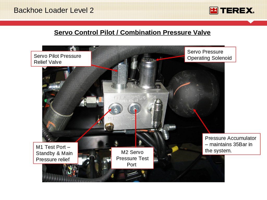
Backhoe Loader Level 2Servo Control Pilot / Combination Pressure Valve
Servo Pressure
Operating Solenoid
Servo Pilot Pressure
Relief Valve
M1 Test Port –
Standby & Main
Pressure relief
M2 Servo
Pressure Test
Port
Pressure Accumulator
– maintains 35Bar in
the system.
17.
Backhoe Loader Level 2Servo Control Pilot / Combination Pressure Valve
The servo control combination valve
reduces the 207bar pressure from the
backhoe valve to 35bar.
The reduced pressure is then used by the
joystick controllers to operate the opening
and closing of the spools in the backhoe
valve.
In the event of a total machine failure, a
gas accumulator is fitted to allow the
controls to be operated to return the boom
and bucket to a safe position with the aid
of gravity.
18.
Backhoe Loader Level 2Change over valve
ISO to SAE
Servo Control
Hydraulic
Schematic
Servo Control Pilot / Combination
Pressure Valve + Accumulator
19.
Backhoe Loader Level 2Servo Assisted Backhoe Console
Configuration Changeover Valve –
This enables the controls to be
switched from (1) ISO (European
community only) to (2) SAE (NonEuropean community).
Servo Console Position Lock – The console has
two operating positions (1) Working position
depressed override button once to activate the
controls (2) Transport position controls will ONLY
operate in the transport position with either of the
override buttons depressed.
1
2
Override Buttons located on the front
of the joystick
controls.
20.
Backhoe Loader Level 221.
Backhoe Loader Level 2Servo Machines Cab Fit Hose Connections
Hoses no colour
Pilot / Combination Valve +
Accumulator
Valve
Mounting
Bracket
Backhoe Control
Valve
Connect 4 colour coded hoses to the “T” pieces on the pilot valve as shown above before fitting the cab.
When the cab is fitted, connect and secure 4 colour coded hoses in order as shown above to the
connectors on the valve bracket.
Next connect & secure the 4 remaining colour coded hoses in order as shown above to the connectors on
the digger valve.
22.
Backhoe Loader Level 2Joystick Controller
When not activated the control lever is held in zero position
by the four return springs (8). The control ports (1,2,3,4) are
connected to the tank port T via the drilling (11).
With deflection of the control lever (5) the plunger (9) pushes
against the return spring (8) and the control spring (7). The
control spring (7) firstly moves the control spool (6)
downwards and closes the connection between the
appropriate port and tank port T. At the same time the
appropriate port is connected to the port P via the drilling
(11). The control phase begins as soon as the control spool
(6) has found its balance between the force of the control
spring (7) and the force which results from the hydraulic
pressure in the appropriate port(1,2,3,or 4).
Through the interaction of control spool (6) and control spring
(7) the pressure in the appropriate ports is proportional to the
stroke of the plunger (9) and thus the position of the control
lever (5).
A rubber gaiter (12) protects the mechanical components of
the housing from contamination.
23.
Backhoe Loader Level 2THANK – YOU !!!
HOPEFULLY YOU HAVE LEARNT SOMETHING AND CAN GO AWAY WITH
SOME USEFULL KNOWLEDGE AND INFORMATION.
MANY THANKS FOR YOUR TIME.